
Data Sheet
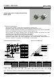

POWER - NIKKOHM
35W HIGH POWER RESISTORS
RMP-20S
Specifications
Type RMP-20S Test Conditions
Rating Power 35 W -55 °C to 25 °C flange temperature
Rating Power 1 Watt Free air.
Heat Resistance 3.3 °C/W Hot spot to flange
Resistance Range 0.01-0.091 Ohm 0.1-510 k Ohm 10-51k Ohm Note 2
Nominal Resistance E6 E24+ E24 Include 2.5, 4.0, 5.0, 8.0 and 16
TCR(ppm/°C) 250(H)* 100 (A) 50 (C) Note 3
Tolerance 5%(J) 1% (F), 5% (J) +/-1% (F) 1% tolerance at 0.01-0.091 ohm is available optionally.
Thick Film Thin Film
Capacitance 1.44pF Equivalent parallel capacitance.
Inductance 8.38nH Equivalent series inductance
Operation Temp. -55 °C to+175 °C
Max. Operating Volt. smaller value either 700V or
RP
P is rating power and R resistance
Withstanding Volt. 2000 VAC Terminal and flange, 60 seconds, 1mA
Load Life +/- 1.0 % 25 °C, 90 min. ON, 30 min. OFF, 1000 hours.
Humidity +/- 1.0 % 40C, 90-95%RH, DC 0.1W, 1000 hours.
Temp. Cycle +/- 0.25 % -55 °C,30 min.,+155 °C,30 min., 5cycles
Soldering Heat +/- 0.1 % 350+/-5 °C, 3seconds,
Solder ability Over 95% of surface 230+/-5 °C, 3seconds.
Insulation Resistance Over 1,000 Meg ohm Between terminals and flange.
Vibration +/- 0.25 % IEC60068-2-6, see note 4
Weight 2.1 grams
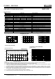
Frequency Characteristics
Impedance (ohm)
1k
RMP-20S C1K0F
RMP-20S C101F
100
RMP-20S C100F
10
RMP-20S C500F
RMP-20S C220F
1
100k 1M 10M 100M 1G
Frequency (Hz)
Note:
(1) Insulating material is unnecessary between flange and heat-sink, flange and resistor is separated by alumina substrate.
(2) Resistance measurement shall be made at a point 5.27mm +/-0.6 mm from the resistor body.
(3) TCR of low resistance will be increased as 300ppm/0.02ohm, 200ppm/0.05ohm, 140ppm/0.1ohm and 80ppm/0.2ohm typically.
Testing point is at 5.27mm from bottom of molding of terminals.
(4) Test method is IEC60068-2-6, and specification is sine sweep wave form, 100Hz-2000Hz, 10 cycles, amplitude 0.75mm or 100m/s
2
,
90minutes. direction x-y z, Amplitude 0.75mm will be applied under break point Frequency (about 60Hz) and 100m/ s
2
over break point
(5) When mounting resistor on heat-sink by screw, clip and pressure strip with using heat conduction grease on back side of resistor are
recommended. Recommended screw torque is 0.5-0.6Nm.
(6) 0.1% tolerance resistors is available, please see datasheet of RNP-20P.
(
7
)
Standard
p
acka
g
in
g
is RoHS PS/PE tube
p
acka
g
in
g,
which contains 50
p
cs / tube.
RoH
S
Typical TCR in Low Ohms
Pulse Energy Durability
Nikkohm Co., Ltd. 3-31-2640 Minamicho, Misawa, Aomori 033-0036 Japan TEL: +81-176-53-2105, FAX: +81-176-53-2106
Copyright © Nikkohm Co., Ltd. URL: http://www.nikkohm.co.jp & http://www.nikkohm.com / e-mail: info@nikkohm.co.jp
10n 100n 1u 10u 100u 1m 10m 100m 1 10 100
Pulse width (seconds)
100k
10k
1k
100
10
Pulse peak power (W)
RMP-20S C100F
Typical continuous-pulse power allows at duty 0.01.
More load life test will be necessary in actual equipment,
Because curve will be changed by resistance, repetition, duty and
operating temperature. Dotted line shows assumption.
400W
35W
Temperature Rise
Derating
-55 0 50 100 150 200
Flange Temperature (deg C)
50
40
30
20
10
0
Ratin
g
Power
(
W
)
0 10 20 30 40 50
Applied Power (W)
100
80
60
40
20
0
Temperature Rise (deg C)
Hot spot temperature of
resistor referred to
flan
g
e temperature.
0.01 0.1 1.0
Resistance (Ohms)
TCR (ppm/deg C) at 0 to 100 deg C
250
200
150
100
50
0
+25°C
+175°C