
Data Sheet

POWER – NIKKOHM
TO126 20W HIGH POWER RESISTORS RNP-10S
20161101
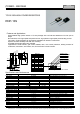
Frequency Characteristics
Impedance (Ω)
1K
RNP-10S C1K0F
RNP-10S C101F
100
RNP-10S C500F
RNP-10S C100F
10
RNP-10S A5R0F
1
10k
100k 1M 10M 100M 1G
Frequency(Hz)
Derating Curve
Rating Power(W), with 2.8°C/W heat sink.
Temperature Rise
Temperature(°C)
Note
(1) Insulation material is unnecessary between flange and heat-sink, because flange and resistor are separated by alumina insulated
substrate. When mounting resistor on
heat-sink, screw, clip and pressure strip with using heat conduction grease on back side of resistor are recommended. Recommended
screw torque is 0.5-0.6Nm.
(2) Resistance measurement shall be made at a point 5.27mm +/-0.6 mm from the resistor body.
(3) TCR of low resistance will be increased as 300ppm/0.02Ω, 200ppm/0.05Ω, 140ppm/0.1Ω and 80ppm/0.2Ω typically. Testing point is
at 5.27mm from bottom of molding of terminals.
(4) Test method is IEC60068-2-6, and specification is sine sweep wave form, 100Hz-2000Hz, 10 cycles, amplitude 0.75mm or 100m/s
2
,
90minutes. direction x-y z, Amplitude 0.75mm will be applied under break point Frequency (about 60Hz) and 100m/ s
2
over break point
(5) 0.1% tolerance resistors is available, please see datasheet of RNP-10P.
RoH
S
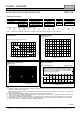
Ordering Information
RNP-10S C 10R0 (*) F Z03 Note
| | | | | |
RNP-10S H(250ppm) > R02-R09 (+E6) > J(5%) Z03 > Tube/60pcs
A(100ppm) > R10-510K (+E24) > F(1%), J(5%) Z05 > Tray/100pcs
C(50ppm) > 10R-51K (+E24) > F(1%)
Resistance value (*) is available following modified E24, +E24.
1.0 1.1 1.2 1.3 1.5 1.6 1.8 2.0 2.2 2.4 2.5 2.7 3.0 3.3
3.6 3.9 4.0 4.3 4.7 5.0 5.1 5.6 6.2 6.8 7.5 8.0 8.2 9.1
Note*: When ordering, additional ohm resistance notation is recommended for keeping out of misunderstanding.
-50 0 50 100 150 200
Flange Temperature (°C)
+25°C
+175°C
24
20
16
12
8
4
0
0 10 20
Application Power (W)
140
120
100
80
60
40
20
0
Nikkohm Co., Ltd. 3-31-2640 Minamicho, Misawa, Aomori 033-0036 Japan TEL: +81-176-53-2105, FAX: +81-176-53-2106
© Nikkohm Co., Ltd. All rights reserved. 2014. URL: http://www.nikkohm.co.jp & http://www.nikkohm.co.jp / e-mail: info@nikkohm.co.jp
Pulse Peak Power
10n 100n 1u 10u 100u 1m 10m 100m 1 10
パルス幅(seconds)
100k
10k
1k
100
10
Pulse Peak Power (W)
RNP-10S C100F
200W
20W
Tentative continuous-pulse power allowance at duty 0.01.
Load life test will be necessary in actual equipment,
Because curve will be changed by resistance, repetition,
duty and operating temperature.