
Data Sheet

POWER - NIKKOHM
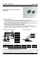
35W HIGH POWER RESISTORS
RNP-20S
Specifications
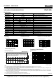
Type RNP-20S Test Conditions
Rating Power 35 W -55 °C to 25 °C flange temperature
Rating Power 1 Watt Free air.
Heat Resistance 3.3 °C/W Heat resistance between hot spot and flange
Resistance Range 0.01-0.091 Ohm 0.1-510 k Ohm 10-51k Ohm Note 2
Nominal Resistance E6 E24+ E24 Include 2.5, 4.0, 5.0, 8.0 and 16
TCR(ppm/°C) 250(H)* 100 (A) 50 (C) Note 3
Tolerance 5%(J) 1% (F), 5% (J) +/-1% (F) 1% tolerance at 0.01-0.091 ohm is available optionally.
Resistor Material Thick Film Thin Film
Capacitance 1.44pF Equivalent parallel capacitance.
Inductance 8.38nH Equivalent series inductance
Operation Temp. -55 °C to+175 °C
Max. Operating Volt. smaller value either 500V or
RP
P is rating power and R resistance
Withstanding Volt. 2000 VAC Terminal and flange, 60 seconds, 1mA
Load Life +/- 1.0 % 25 °C, 90 min. ON, 30 min. OFF, 1000 hours.
Humidity +/- 1.0 % 40C, 90-95%RH, DC 0.1W, 1000 hours.
Temp. Cycle +/- 0.25 % -55 °C,30 min.,+155 °C,30 min., 5cycles
Soldering Heat +/- 0.1 % 350+/-5 °C, 3seconds,
Solder ability Over 95% of surface 230+/-5 °C, 3seconds.
Insulation Resistance Over 1,000 Meg ohm Between terminals and flange.
Vibration +/- 0.25 % IEC60068-2-6, see note 4
Weight 2.1 grams
20161101
Note:
(1) Insulating material is unnecessary between flange and heat-sink, flange and resistor is separated by alumina substrate.
(2) Resistance measurement shall be made at a point 5.27mm +/-0.6 mm from the resistor body.
(3) TCR of low resistance will be increased as 300ppm/0.02ohm, 200ppm/0.05ohm, 140ppm/0.1ohm and 80ppm/0.2ohm typically. Testing point is at
5.27mm from bottom of molding of terminals.
(4) Test method is IEC60068-2-6, and specification is sine sweep wave form, 100Hz-2000Hz, 10 cycles, amplitude 0.75mm or 100m/s
2
, 90minutes. direction
x-y z, Amplitude 0.75mm will be applied under break point Frequency (about 60Hz) and 100m/ s
2
over break point
(5) When mounting resistor on heat-sink by screw, clip and pressure strip with using heat conduction grease on back side of resistor are recommended.
Recommended screw torque is 0.5-0.6Nm.
(6) 0.1% tolerance resistors is available, please see datasheet of RNP-20P.
(7) Standard packaging is RoHS PS/PE tube packaging, which contains 50pcs / tube.
RoH
S
Frequency Characteristics
Impedance (ohm)
1k
RNP-20S C1K0F
RNP-20S C101F
100
RNP-20S C100F
10
RNP-20S C500F
RNP-20S C220F
1
100k 1M 10M 100M 1G
Frequency (Hz)
Pulse Energy Durability
10n 100n 1u 10u 100u 1m 10m 100m 1 10 100
Pulse width (seconds)
100k
10k
1k
100
10
Pulse peak power (W)
RNP-20S C100F
Tentative continuous-pulse power allowance at duty 0.01.
Load life test will be necessary in actual equipment,
Because curve will be changed by resistance, repetition,
dut
y
and o
p
eratin
g
tem
p
erature.
400W
35W
Temperature Rise
0 10 20 30 40 50
Applied Power (W)
100
80
60
40
20
0
Temperature Rise (°C)
Hot spot temperature of
resistor referred to
flan
g
e temperature.
Typical TCR in Low Ohms
0.01 0.1 1.0
Resistance (Ohms)
TCR (ppm/°C) at 0 to 100 °C
250
200
150
100
50
0
Derating
-55 0 50 100 150 200
Flange Temperature (°C)
50
40
30
20
10
0
Ratin
g
Power
(
w
)
+25°C
+175°C
Nikkohm Co., Ltd. 3-31-2640 Minamicho, Misawa, Aomori 033-0036 Japan TEL: +81-176-53-2105, FAX: +81-176-53-2106
Copyright © Nikkohm Co., Ltd. URL: http://www.nikkohm.co.jp & http://www.nikkohm.com / e-mail: info@nikkohm.co.jp