
Data Sheet

POWER - NIKKOHM
50W TO263 HIGH POWER RESISTORS
(D2PAK)
RNP-50E
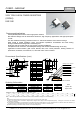
Dimensional Specifications (mm)
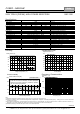
Ordering Information
RNP-50E C 10R0 (*) F Z01 Note
| | | | |
RNP-50E H ( >250ppm) > R02-R09 (+E6) > J(5%) Z01 > Tape & reel
A (100ppm) > R10-510K(+E24) > F(1%), J(5%) Z03 50pcs / tube
C (50ppm) > 10R-51K (+E24) > F(1%)
Resistance value (*) is available following modified E24, +E24.
1.0 1.1 1.2 1.3 1.5 1.6 1.8 2.0 2.2 2.4 2.5 2.7 3.0 3.3
3.6 3.9 4.0 4.3 4.7 5.0 5.1 5.6 6.2 6.8 7.5 8.0 8.2 9.1
Note*: When ordering, additional ohm resistance notation is recommended for keeping out of misunderstanding.
.
Features and Applications
TO263 (D2PAK) 50W surface mount high power resistors.
Non-inductive design suits for automotive electronics, high frequency applications and high-speed pulse
circuits.
Thin film metalize technology presents lowest 2.3 °C/W heat resistance from resistor to flange
Wide, 20mΩ to 510kΩ resistance range, non-inductive impedance characteristic and heat venting
through insulated metal flange aids circuit designers.
Small size and thin profile suits for high-density compact installations.
Complete thermal conduction, heat dissipation design and vibration durable design to be easy.
Applications include snubber, gate control, bleeder, filter, rush current protection, braking resistors of
automotive, rail traction, wind turbine, PV, UPS and motor control inverters.
.
RoH
S
Nikkohm Co., Ltd. 3-31-2640 Minamicho, Misawa, Aomori 033-0036 Japan TEL: +81-176-53-2105, FAX: +81-176-53-2106
© Nikkohm Co., Ltd. All rights reserved. URL: http://www.nikkohm.co.jp & http://www.nikkohm.com / e-mail: info@nikkohm.com
RNP-20E
mm +/-mm
A 10.1 +/-0.2
B 10.3 +/-0.2
C 4.5 +/-0.2
D - -
E 5.0 +/-1.0
F 2.5 +/-0.5
G 2.2 +/-0.2
H 2.75 +/-0.2
J 0.5 +/-0.05
K 0.75 +/-0.05
L 1.5 +/-0.05
M 5.08 +/-0.10
N 1.5 +/-0.05
RNP50E
100
CF 62
C A
B
F
E
G
J
H
M
K
L
N
K
11.0
1.6
5.08
10.0
15.8
3.50
Leads, Tin plated Cu
Molding, epoxy, UL94-V0
Leads joint, 85%Pb-Sn solder
Resistor, Ni-Cr or RuO
Substrate, Alumina
Joint, Sn-Ag-Cu solder
Between flange and resistor is insulated.
Flange, matte tin plated Cu
Note:
(1) Resistance measurement shall be made at a point 5.27mm +/-0.6 mm from the resistor body.
(2) TCR of low resistance will be increased as 300ppm/0.02Ω, 200ppm/0.05Ω, 140ppm/0.1Ω and 80ppm/0.2Ω typically. Testing point is at 5.27mm from bottom
of molding of terminals.
(3) Test method is IEC60068-2-6, and specification is sine sweep wave form, 100Hz-2000Hz, 10 cycles, amplitude 0.75mm or 100m/s
2
, 90minutes. direction x-y z,
Amplitude 0.75mm will be applied under break point Frequency (about 60Hz) and 100m/ s
2
over break point
(6) Standard packaging is anti-static PE tape and reel, reel contains 500pcs/reel.