0-16x Lees de volledige handleiding vóór installatie en ingebruikname. 1. BESCHRIJVING Deze videobuitenpost uit het Niko toegangscontrolegamma maakt altijd deel uit van een systeem met één of meerdere binnenposten en een voeding. Meer informatie over de integratie van het product in een volledig systeem vind je terug in de catalogus. De buitenpost is een compacte opbouwpost met een opbouwhoogte van 16 mm.
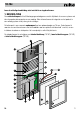
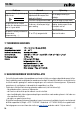
10-16x 2. ONDERDELEN 2.1. Basisonderdelen 1. camera 2. luidspreker 3. opening voor sleuteltje 4. connector voor servicetoestel 5. microfoon 6. naamplaatje 7. potentiometers voor volumeregeling van de microfoon en luidspreker 8. aansluitklemmen 9. kabeldoorvoer 10. gaten voor wandmontage 11. metalen afschermkap 12. klemveren om het naamplaatje te bevestigen 13. naamkaartje 14. infraroodleds 15. lichtsensor 16. aansluitpunt voor naamplaatverlichting 17. lichtelement voor naamplaatje 18. serienummer 19.
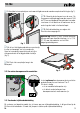
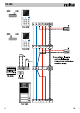
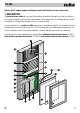
10-16x 1. Verwijder het naamplaatje en maak voorzichtig de connector voor de naamplaatverlichting los (fig. 1). 2. Bevestig de buitenpost aan de muur. De aangewezen montagehoogte voor de camera is 160 tot 170 cm vanaf de grond. Breng de kabel van onder naar boven in het toestel om te voorkomen dat er water langs de kabel in het toestel loopt. 3. Sluit de bekabeling aan volgens het aansluitschema op pagina 4. fig.
10-16x OFF ON a b E P M V1 V2 10-570 OFF ON a b E P M V1 V2 10-570 24V / 1A 19 20 21 22 a b P V1 V2 1 3 10-806 230V~ a b R P M V1 V2 10-162 4 NL
10-16x 4. PROGRAMMERING EN GEBRUIK 4.1. Programmeren van een beldrukknop De programmering van een beldrukknop is uitvoerig beschreven in de handleiding van de systeemvoeding (10-801, 10-802 of 10-806) of het servicetoestel (10-870). Als je het servicetoestel gebruikt, scheur dan het serienummer af dat je terugvindt achter het naamplaatje of in de doos. Kleef dit serienummer op het installatieschema. Je kunt slechts twee binnenposten programmeren op de geheugenplaats van elke beldrukknop.
10-16x 4.5. Tijden instellen Standaard zijn de volgende tijden geprogrammeerd: spreektijd na het starten van een gesprek max. 2 min duur dat het camerabeeld actief blijft 80 s duur dat een oproep van een buitenpost gesignaleerd blijft 2 min Je kunt ook andere tijden instellen via: • de voeding. Raadpleeg de handleiding van de voeding voor meer informatie over het programmeren via de voeding. • het servicetoestel.
10-16x Probleem Oorzaak Oplossing Negatieve toon als je drukt op de Fout in de programmering of Wis de programmering en beldrukknop. bijbehorende binnenpost niet herbegin. goed geïnstalleerd. Installatie in programmeermode. Verlaat de programmeermode. Controleer de bekabeling aan de De spraakfunctie en andere De binnen- of buitenpost krijgt voeding, de binnenpost en de functies (bv. deuropener) werken, geen voeding. buitenpost met het maar er is geen beeld. aansluitschema.
10-16x 9. GARANTIEBEPALINGEN - De garantietermijn bedraagt vier jaar vanaf leveringsdatum. Als leveringsdatum geldt de factuurdatum van aankoop van het product door de consument. Als er geen factuur voorhanden is, geldt de productiedatum. - De consument is verplicht Niko schriftelijk te informeren over het gebrek aan overeenstemming, en dit uiterlijk binnen de twee maanden na vaststelling.
10-16x Veuillez lire le mode d’emploi entièrement avant l’installation et la mise en service. 1. DESCRIPTION Ce poste extérieur vidéo de la gamme Contrôle d’accès de Niko fait toujours partie d’un système à un ou plusieurs postes intérieurs et une alimentation. Vous trouverez dans le catalogue de plus amples informations sur l’intégration du produit dans un système complet. Le poste extérieur est un poste en saillie compact d’un encombrement de 16 mm.
-16x 2. PIÈCES 2.1. Éléments de base 1. caméra 2. haut-parleur 3. ouverture pour la clé 4. connecteur pour l’appareil de service 5. microphone 6. porte-étiquette 7. potentiomètres pour le réglage du volume du microphone et du haut-parleur 8. bornes de raccordement 9. passe-câble 10. trous pour montage mural 11. capot protecteur en métal 12. ressorts de fixation du porte-étiquette 13. étiquette 14. LED à infrarouge 15. capteur de lumière 16. point de raccordement de l’éclairage du porte-étiquette 17.
10-16x 1. Retirer le porte-étiquette et détacher prudemment le connecteur de l’éclairage du porte-étiquette (fig. 1). 2. Fixer le poste extérieur au mur. La hauteur de montage conseillée pour la caméra est de 160 à 170 cm par rapport au sol. Entrer le câble dans l’appareil du bas vers le haut afin d’éviter que de l’eau entre dans l’appareil le long du câble. 3. Raccorder le câblage conformément au schéma de raccordement en page 12. fig.
10-16x OFF ON a b E P M V1 V2 10-570 OFF ON a b E P M V1 V2 10-570 24V / 1A 19 20 21 22 a b P V1 V2 1 3 10-806 230V~ a b R P M V1 V2 10-162 12 FR
10-16x 4. PROGRAMMATION ET UTILISATION 4.1. Programmer un bouton-poussoir de sonnerie La programmation d’un bouton-poussoir de sonnerie est décrite en détail dans le mode d’emploi du système d’alimentation (10-801, 10-802 ou 10-806) ou de l’appareil de service (10-870). Si vous utilisez l’appareil de service, détachez le numéro de série qui se trouve derrière le porte-étiquette ou dans la boîte. Collez ce numéro de série sur le schéma d’installation.
10-16x 4.4. Régler le volume sur le poste extérieur En dessous du porte-étiquette, il y a deux potentiomètres qui permettent de régler le volume sur le poste extérieur. potentiomètre pour haut-parleur (volume sur le poste extérieur) potentiomètre pour microphone (volume sur le poste intérieur) 4.5. Régler les temps Les temps suivants sont programmés de manière standard: temps de parole après le début d’une conversation max.
10-16x Problème Tonalité négative lorsque vous appuyez sur le bouton-poussoir de sonnerie. Cause Erreur dans la programmation ou le poste intérieur correspondant mal installée. Installation en mode de programmation. La fonction de parole et d’autres fonctions (p.ex. ouvre-porte) Le poste intérieur ou extérieur fonctionnent, mais il n’y a pas n’est pas alimenté. d’image. L’image est entièrement brouillée et impossible à reconnaître V1 et V2 inversées. (formation de bandes, …).
10-16x 9. DISPOSITIONS DE GARANTIE - Le délai de garantie est de quatre ans à partir de la date de livraison. La date de la facture d’achat par le consommateur est considérée comme la date de livraison. En l’absence de facture, la date de fabrication est valable. - Le consommateur est tenu de prévenir Niko par écrit de tout défaut de conformité, dans un délai maximum de deux mois après constatation.
10-16x Handbuch vor Montage und Inbetriebnahme vollständig durchlesen. 1. BESCHREIBUNG Diese Video-Außensprechstelle aus dem Programm Niko-Zugangskontrolle ist integrativer Bestandteil eines aus einer oder mehreren Innensprechstellen mitsamt Netzteil bestehenden Türsprechsystems. Weitere Informationen über die Integration des Produkts in das gesamte Türsprechsystem erhalten Sie im Katalog. Bei der Außensprechstelle handelt es sich um ein kompakt ausgeführtes Aufputzgerät mit einer Aufbauhöhe von 16 mm.
10-16x 2. KOMPONENTEN 2.1. Basiskomponenten 1. Kamera 2. Lautsprecher 3. Schlüsselöffnung 4. Anschluss für Servicegerät 5. Mikrofon 6. Namensschild 7. Potentiometer für Lautstärkeregelung von Mikrofon und Lautsprecher 8. Anschlussklemmen 9. Leitungsdurchführung 10. Befestigungslöcher für Wandmontage 11. Gerätedeckel aus Metall 12. Klemmfedern für Befestigung von Namensschild 13. Beschriftungskarte 14. Infrarot-LEDs 15. Lichtsensor 16. Anschlusspunkt für Namensschildbeleuchtung 17.
10-16x 1. Entfernen Sie das Namensschild und lösen Sie vorsichtig den Anschluss für die Namensschildbeleuchtung (Abb. 1). 2. Montieren Sie das Außengerät an der Wand. Die geeignete Montagehöhe der Kamera beträgt 160 bis 170 cm ab Boden. Führen Sie das Kabel von unten nach oben in das Gerät ein. Dadurch verhindern Sie, dass Wasser entlang des Kabels in das Gerät eindringen kann. Abb. 1 3. Schließen Sie die Verdrahtung nach dem auf Seite 20 abgebildeten Anschlussplan an.
10-16x OFF ON a b E P M V1 V2 10-570 OFF ON a b E P M V1 V2 10-570 24V / 1A 19 20 21 22 a b P V1 V2 1 3 10-806 230V~ a b R P M V1 V2 10-162 20 DE
10-16x 4. PROGRAMMIERUNG UND BEDIENUNG 4.1. Klingeltaster programmieren Das Programmieren auf einen Klingeltaster wird ausführlich in den Handbüchern der Anlagennetzteile (10-801, 10-802 oder 10-806) bzw. des Servicegeräts (10-870) beschrieben. Ziehen Sie, wenn Sie ein Servicegerät einsetzen, von der Namensschildrückseite oder von der Verpackung den Seriennummernaufkleber ab und kleben Sie diesen in den Installationsplan ein.
10-16x 4.4. Lautstärke von Außensprechstelle regeln Unterhalb des Namensschilds befinden sich zwei Potentiometer, mit denen Sie die Lautstärke der Außensprechstelle regeln können. Potentiometer für Lautsprecher (Lautstärke von Außensprechstelle) Potentiometer für Mikrofon (Lautstärke von Innensprechstelle) 4.5. Zeiten einstellen Standardmäßig sind folgende Zeiten vorprogrammiert: Sprechzeit nach Start eines Gesprächs max.
10-16x Problem Warnton bei Betätigung des Klingeltasters. Sprachfunktion und andere Funktionen (z.B. Türöffner) funktionieren, es erscheint jedoch kein Bild. Das Bild ist vollkommen gestört und nicht erkennbar (Streifenbildung etc.). Ursache Programmierfehler bzw. dazugehörige Innensprechstelle nicht korrekt installiert. Installationsanlage im Programmiermodus. Keine elektrische Versorgung von Innen- oder Außensprechstelle. V1 und V2 sind vertauscht.
10-16x 9. GARANTIEBEDINGUNGEN - Der Garantiezeitraum beträgt vier Jahre ab Lieferdatum. Als Lieferdatum gilt das Rechnungsdatum zum Zeitpunkt des Kaufs durch den Endverbraucher. Falls keine Rechnung mehr vorhanden ist, gilt das Produktionsdatum. - Der Endverbraucher ist verpflichtet, Niko schriftlich über einen Produktmangel innerhalb von zwei Monaten nach dessen Feststellung zu informieren. - Im Falle eines Mangels hat der Endverbraucher nur Recht auf kostenlose Reparatur oder Ersatz des Produkts.
10-16x Read the complete user manual before carrying out the installation and activating the system. 1. DESCRIPTION This external video unit from the Niko Access Control range is always a standard part of a system with one or more internal units and a power supply. More information on how the product is integrated into a complete system can be found in the catalogue. The external unit is a compact surface-mounting unit with a 16 mm mounting height.
10-16x 2. COMPONENTS 2.1. Basic components 1. camera 2. loudspeaker 3. opening for key 4. service set connector 5. microphone 6. nameplate 7. potentiometers for volume adjustment of the microphone and loudspeaker 8. connection terminals 9. cable inlet 10. holes for wall mounting 11. metal protective cap 12. clamping springs for fixing the nameplate 13. namecard 14. infrared LEDs 15. light sensor 16. connection point for nameplate lighting 17. lighting element for nameplate 18. serial number 19.
10-16x 1. Remove the nameplate and carefully loosen the connector for the nameplate lighting (fig. 1). 2. Mount the external unit on the wall. The recommended installation height for the camera is 160 to 170 cm from the ground. Run the cable from the bottom up in the device in order to avoid water entering the device via the cable. 3. Connect the wiring as shown in the wiring diagram on 28.
10-16x OFF ON a b E P M V1 V2 10-570 OFF ON a b E P M V1 V2 10-570 24V / 1A 19 20 21 22 a b P V1 V2 1 3 10-806 230V~ a b R P M V1 V2 10-162 28 EN
10-16x 4. PROGRAMMING AND USE 4.1. Programming the bell push button Programming of a bell push button is described in detail in the manual of the system power supply (10801, 10-802 or 10-806) or the service set (10-870). If you use the service set, tear off the serial number that you will find behind the nameplate or in the box. Stick this serial number on the installation diagram. You can programme only two internal units in the memory location of each bell push button.
10-16x 4.4. Adjusting the volume on the external unit There are two potentiometers under the nameplate with which you can adjust the volume on the external unit. potentiometer for loudspeaker (volume on external unit) potentiometer for microphone (volume on internal unit) 4.5. Setting times By default, the following times are programmed: speech time after initiating a call max.
10-16x Problem Cause Programming error or Negative tone when pressing the associated internal unit not bell push button. correctly installed. Installation in programming mode. Speech and other functions (e.g. The internal or external unit door opener) are working, but receives no power. there is no image. The image is completely disturbed and unrecognisable V1 and V2 are reversed. (striping, …). Solution Erase programming, then restart programming. Quit programming mode.
10-16x 9. GUARANTEE PROVISIONS PM010-16x00R11342 - The period of guarantee is four years from the date of delivery. The delivery date is the invoice date of purchase of the product by the consumer. If there is no invoice, the date of production applies. - The consumer is obliged to inform Niko in writing about the non-conformity, within two months after stating the defect.