
Owner's Manual


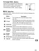

Table Of Contents
- Using the Supplied Manuals
- Quick Start Guide
- Owners Manual
- Two-Button Reset
- Setting Language / Time / Date
- Image Quality / Size
- Table of Contents
- Q & A Index
- Icons Used in This Manual
- Supplied Accessories
- Parts & Controls
- Tutorials
- Getting Started
- Basic Photography
- Basic Playback
- Image Quality
- Image Size
- Focus
- Release Mode
- ISO Sensitivity
- Exposure
- White Balance
- Image Enhancement
- Flash Photography
- Other Shooting Options
- More Playback Options
- Connecting to Other Devices
- Menu Guide
- Playback Menu - Managing Images
- Shooting Menu - Shooting Options
- Shooting Menu Bank
- Reset Shooting Menu
- Active Folder
- File Naming
- Image Quality
- Image Size
- JPEG Compression
- NEF (RAW) Recording
- White Balance
- Set Picture Control
- Managing Picture Control
- Color Space
- Active D-Lighting
- Long Exposure NR
- High ISO NR
- ISO Sensitivity Settings
- Live View
- Multiple Exposure
- Interval Timer Shooting
- Custom Settings - Fine Tuning the Camera
- Setup Menu - Camera Setup
- Retouch Menu - Creating Retouched Copies
- My Menu - Creating a Custom Menu
- Compatible Lenses
- Optional Flash Units
- Other Accessories
- Care / Maintenance
- Troubleshooting
- Error Messages
- Defaults
- Memory Card Capacity
- Specs
- Index
- Software Installation Instructions
- Scans of Software CD-ROM
- Warranty

iii
The Flash Sync
Mode
Display
~
does
not
appear in
the
control panel flash sync mode display when
[-
-]
is
selected for [Built-in flash] > [Mode].
B Flash Compensation
The flash compensation value selected
with
the
~
(~)
button
and sub-
command dial
is
added
to
the
flash compensation values selected for
the
built-in flash,
group
A,
and
group
B in
the
[Commander mode] menu. A
~
icon
is
displayed in
the
control panel and viewfinder when a flash
compensation value
other
than +0
is
selected for [Built-in flash] > [TTL].
The
~
icon flashes when
the
built-in flash
is
in
mode
[M].
~
Commander
Mode
Position
the
sensor windows on
the
remote flash units
to
pick
up
the
monitor
preflashes from
the
built-in flash (particular care
is
required when
not
using a tripod).
Be
sure
that
direct
light
or
strong reflections from
the
remote flash units
do
not
enter
the
camera lens (in
TTL
mode)
or
the
photocells on
the
remote flash units (AA mode),
as
this may interfere
with
exposure.
To
prevent
timing
flashes
emitted
by the built-in flash from
appearing in photographs taken at short range, choose
low
ISO
sensitivities
or
small apertures (large f-numbers)
or
use
an
optional
5G-31R
infrared panel for
the
built-in flash.
An
5G-31R
is
required for best results
with
rear-curtain sync, which produces brighter
timing
flashes. After
positioning
the
remote flash units, take a test shot and view
the
results in
the
camera monitor.
Although
there
is
no
limit
on
the
number
of
remote flash units
that
may
be used,
the
practical
maximum
is
three. With more than this number,
the
light
emitted
by
the
remote flash units will interfere
with
performance.
297