Autofocus Speedlight SB-700 User’s Manual En
About the SB-700 and This User’s Manual Preparation A Thank you for purchasing the Nikon Speedlight SB-700. To get the most out of your Speedlight, please read this user’s manual thoroughly before use. How to find what you are looking for i Table of contents (0A-11) You can search by item, such as operation method, ash mode or function. i Q&A index (0A-9) You can search according to objective without knowing the speci c name or term of an item.
❑ Speedlight Stand AS-22 ❑ Nikon Diffusion Dome SW-14H ❑ Incandescent Filter SZ-3TN ❑ Fluorescent Filter SZ-3FL ❑ Soft Case SS-700 ❑ User’s manual (this manual) ❑ A collection of example photos ❑ Warranty card Soft Case SS-700 Speedlight Stand AS-22 SB-700 Incandescent Filter SZ-3TN Fluorescent Filter SZ-3FL Nikon Diffusion Dome SW-14H A–3 A Preparation Included items
About the SB-700 and This User’s Manual About the SB-700 Preparation A The SB-700 is a high-performance Speedlight compatible with Nikon Creative Lighting System (CLS) with a guide number of 28/39 (ISO 100/200, m) (92/128, ft.) (at the 35 mm zoom head position in Nikon FX format with standard illumination pattern, 20 °C/68 °F).
Icons used in this manual t 0 Includes information or tips to make Speedlight use easier. A Preparation v Describes a point to which you should pay particular attention in order to avoid Speedlight malfunctions or mistakes. Reference to other pages in this manual t Tips on identifying CPU NIKKOR lenses CPU lenses have CPU contacts. CPU contacts • The SB-700 cannot be used with IX-Nikkor lenses.
About the SB-700 and This User’s Manual Terminology Preparation A Default settings: function and mode settings at the time of purchase Nikon Creative Lighting System (CLS): a lighting system that enables various ash photography functions with improved communication between Nikon Speedlights and cameras Illumination patterns: control types of light falloff at edges; the SB-700 provides three illumination patterns, standard, center-weighted and even.
Monitor pre- ashes: scarcely visible ashes emitted before actual ring that enable the camera to measure the light re ected on a subject i-TTL balanced ll- ash: i-TTL mode type in which ash output level is adjusted to well-balanced exposure of the main subject and background Standard i-TTL: i-TTL mode type in which ash output level is adjusted to the correct exposure of the main subject regardless of background brightness Manual ash mode: ash mode in which the ash output level and aperture are manual
About the SB-700 and This User’s Manual Preparation A Wireless multiple ash-unit photography: ash photography with multiple wireless ash units simultaneously ring Master ash unit: the ash unit that commands remote ash units in multiple ash-unit photography Remote ash unit: a ash unit that res following commands from the master ash unit Advanced Wireless Lighting: wireless multiple ash-unit photography with CLS; multiple remote ash unit groups can be controlled with the master ash unit.
Q&A Index You can search for speci c explanations according to objective.
Q&A Index Preparation A Question Key phrase 0 How can I use autofocus in dim lighting? AF-assist illumination E-27 How can I take pictures of both the subject and background at night? Slow sync E-33 How can I take pictures without the subject’s eyes appearing red? Red-eye reduction E-34 How can I use the SB-700 with a non-CLScompatible SLR camera? Non-CLS-compatible SLR camera F-1 How can I use the SB-700 with a COOLPIX camera? COOLPIX camera G-1 Flash photography 2 (with wireless SB-70
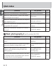
Table of Contents B C D About the SB-700 and This User’s Manual ..........................A-2 Q&A Index .........................................................................A-9 For Your Safety ................................................................A-14 Check before Use ............................................................A-23 Operation Speedlight Parts ................................................................. B-1 Basic Operations ..............................................
Table of Contents Remote Flash Units ..........................................................D-23 Checking Status in Wireless Multiple Flash-unit Photography .................................................................D-27 Preparation A E A–12 Functions Switching Illumination Patterns .......................................... E-2 Bounce Flash Operation ..................................................... E-5 Taking Close-up Photographs ...........................................
F For Use with Non-CLS-compatible SLR Cameras........................................................................ F-1 A G For Use with COOLPIX Cameras....................... G-1 H Tips on Speedlight Care and Reference Information Preparation Troubleshooting .................................................................H-1 Guide Number, Aperture and Flash-to-subject Distance ......H-6 Tips on Speedlight Care .....................................................H-7 Notes on Batteries...........
For Your Safety Preparation A Before using your product, please read the following safety precautions carefully and thoroughly to ensure correct and safe use and to help prevent damage to your Nikon product or injury to yourself or others. For quick reference by those who use the product, please keep these safety instructions near the product.
A–15 A Preparation 4. If the flash unit is dropped and damaged, do not touch any exposed interior metal parts. Such parts, especially the Speedlight’s capacitor and associated parts, could be in a high-charge state and if touched could cause an electric shock. Disconnect the power or remove the batteries and be sure that you do not touch any of the product’s electrical components, and then bring the flash unit to your local Nikon dealer or authorized service center for repair. 5.
For Your Safety Preparation A 8. Do not fire the flash unit directly at the driver of a moving car, as this could temporarily impair the driver’s vision and cause an accident. 9. Do not fire the flash unit directly into the eyes of someone that is at close range, as it could damage the retinas of their eyes. Never fire the flash unit closer than 1 meter from infants. 10. Do not fire the unit while the flash head is touching a person or object.
A–17 A Preparation 15. When using standard size (AA, AAA, C, D) or other common rechargeable batteries such as NiMH batteries, or when recharging them, be sure to use only the battery charger specified by the battery maker and read the instructions thoroughly. Do not recharge these batteries with their terminals reversed in the charger or before the batteries have cooled off sufficiently because they could leak corrosive liquids, explode or catch on fire.
For Your Safety Preparation A 1. 2. 3. 4. 5. CAUTIONS for Speedlights Do not touch the flash unit with wet hands, as this could cause an electric shock. Keep the flash unit away from children to prevent them from putting the unit in or near their mouth, or otherwise touching a dangerous part of the product; as such contact could cause an electric shock. Do not apply strong physical shocks to the unit, as this could cause a malfunction that could cause the unit to explode or catch on fire.
1. Never heat or throw batteries into a fire, as this could cause the batteries to leak corrosive liquids, generate heat or explode. 2. Do not short-circuit or disassemble the batteries because this could cause the batteries to leak corrosive liquids, generate heat or explode. 3. Do not mix battery types, brands or old and new batteries, as this could cause the batteries to leak corrosive liquids, generate heat or explode. 4.
For Your Safety Preparation A 8. If corrosive liquids seep from the batteries and come in contact with your skin or clothes, wash immediately with running water. Prolonged contact could injure your skin. 9. Always follow the warnings and instructions printed on the batteries to avoid activities that could cause the batteries to leak corrosive liquids, generate heat or catch on fire. 10.
A–21 A Preparation 16. When recycling or disposing of batteries, be sure to insulate their terminals with tape. If the battery’s positive and negative terminals short-circuit after coming into contact with metallic objects, it could cause fire, heat generation or an explosion. Dispose of used batteries in accordance with local government regulations. 17. Non-rechargeable batteries should never be charged in a battery charger because they could leak corrosive liquids or generate heat. 18.
For Your Safety CAUTION for Batteries Preparation not throw or apply strong physical shocks to the batteries A Do as this could cause batteries to leak corrosive liquids, generate heat or explode. Symbol for separate collection applicable in European countries This symbol indicates that this product is to be collected separately. The following apply only to users in European countries. • This product is designated for separate collection at an appropriate collection point.
Check before Use Tips on using the Speedlight A Take trial shots Preparation Take trial shots before photographing important occasions such as weddings or graduations. Have Nikon spot-check your Speedlight regularly Nikon recommends that you have your Speedlight serviced by an authorized dealer or service center at least once every two years.
Check before Use Life-long learning Preparation A As part of Nikon’s “life-long learning” commitment to ongoing product support and education, continually updated information is available online at the following websites: • For users in the United States: http://www.nikonusa.com/ • For users in Europe and Africa: http://www.europe-nikon.com/support/ • For users in Asia, Oceania and the Middle East: http://www.nikon-asia.
Preparation A A–25
B Operation Speedlight Parts 6 B Operation 7 8 1 9, 10 11 12 2 13 14 3 15 4 16 5 B–1
1. Flash head 2. Flash head tilting/rotating lock release button (0E-6) B 3. Light sensor window for wireless remote ash (0D-23) Operation 4. Battery chamber cover 5. Battery chamber cover lock release (0B-8) 6. Built-in bounce card (0E-12) 7. Built-in wide panel (0E-14) 8. Flash panel 9. Filter detector 10. Nikon Diffusion Dome detector 11. Flash-ready indicator (in remote mode) (0D-27) 12. AF-assist illuminator (0E-27) 13. External AF-assist illuminator contacts (0H-14) 14. Locking pin 15.
Speedlight Parts 17 Operation B 18 20 19 B–3 21
17. Flash head tilting angle scale (0E-6) 18. Flash head rotating angle scale (0E-6) 19. Flash-ready indicator (0B-15, D-27) 20. LCD panel (0B-16, H-11) B Operation 21.
Speedlight Parts B 22 27 23 28 Operation 24 25 26 B–5 29 30 31
25. [MENU] button Displays custom settings. (0B-18) 26. Selector dial Rotate to change selected item. The selected item is highlighted on the LCD. (0B-16) 27. Illumination pattern selector Selects illumination pattern. (0E-2) 28. [SEL] button (select button) Selects item to be con gured. (0B-16) 29.
Basic Operations This section covers basic procedures in i-TTL mode in combination with a CLS-compatible camera. v Notes on continuous ash photography Operation B • To prevent the SB-700 from overheating, allow it to cool down for at least 10 minutes after 15 times of continuous firing. • When continuous flash firing is repeated in quick succession, the internal safety function adjusts the recycling time by up to 15 seconds.
STEP 1 Inserting the batteries Slide the battery chamber cover open while pressing the battery chamber cover lock release. Insert the batteries following the [+] and [-] marks. Close the battery chamber cover.
Basic Operations Suitable batteries When replacing batteries, use four fresh AA-type batteries of the same brand from any of the following types: Operation B 1.5 V alkaline AA battery 1.5 V lithium AA battery Rechargeable 1.2 V NiMH AA battery • For minimum recycling time and number of flashes for each battery type, refer to “Specifications.” (0H-27) • Alkaline battery performance may vary greatly depending on the manufacturer. • 1.5 V carbon-zinc AA batteries are not recommended.
Replacing/recharging batteries 1.5 V alkaline AA battery 10 seconds or more 1.5 V lithium AA battery 10 seconds or more Rechargeable 1.2 V NiMH AA battery 10 seconds or more B Operation Refer to the following table to determine when to replace batteries with fresh ones or recharge batteries according to how long the ashready indicator takes to come on. Low battery power indicator When battery power is low, the icon shown at the left appears on the LCD and the SB-700 stops functioning.
Basic Operations STEP 2 Attaching the SB-700 to the camera Make sure the SB-700 and the camera body are turned off. B Operation Make sure the mounting foot lock lever is on the left (white dot). Slide the SB-700’s mounting foot into the camera’s accessory shoe. Turn the lock lever to “L.” v Lock the Speedlight in place Turn the lock lever clockwise until it stops at the mounting foot lock index.
Detaching the SB-700 from the camera • If the SB-700’s mounting foot cannot be removed from the camera’s accessory shoe, turn the lock lever 90° to the left again, and slide the SB-700 slowly out. • Do not forcibly remove the SB-700. B–12 B Operation Make sure the SB-700 and the camera body are turned off, turn the lock lever 90° to the left, and then slide the SB-700’s mounting foot from the camera’s accessory shoe.
Basic Operations STEP 3 Adjusting the flash head Adjust the ash head to the front position. Operation B • The flash head is locked at front. LCD indicator for flash head status Flash head is set at front. Flash head is set at angle other than front. (Flash head is tilted up or rotated to the right or left.) Flash head is tilted down.
STEP 4 Turning the SB-700 and camera on Turn the SB-700 and the camera body on. LCD sample • The image below is the SB-700 LCD sample under the following conditions: flash mode: i-TTL mode; image area: DX format; illumination pattern: standard; ISO sensitivity: 100; zoom head position: 35 mm; f-number of aperture: 5.6 • Icons on the LCD may differ depending on the SB-700 settings and the camera and lens in use.
Basic Operations STEP 5 Selecting the flash mode Set the mode selector to [TTL]. Operation B Make sure that the ashready indicator on the SB-700 or in the camera’s view nder is on before taking a picture.
Settings and the LCD • If there is a configurable setting, an icon indicating the setting appears in the bottom right corner. If there are two or more configurable settings, the SEL icon is displayed, indicating configurable items can be selected with the [SEL] button. Press the [SEL] button to highlight the selected item. Change the setting by rotating the selector dial. Press the [OK] button to con rm setting. • Once confirmed, the highlighted item returns to normal display.
Custom Functions and Settings Operation B Various operations for the SB-700 can be easily set using the LCD. • Displayed icons vary according to the combination of camera and status of the SB-700. • Functions and settings indicated with grid boxes do not function even though they can be configured and set.
Custom setting • The highlighted item can be configured. Custom settings Position of highlighted item (within 11 items) This is not displayed while a selected item is being con gured. Items indicated with grid boxes can be con gured but do not effect ash operation. B–18 B Operation Press the [MENU] button to display the custom setting. Rotate the selector dial to choose an item, and then press the [OK] button.
Custom Functions and Settings Rotate the selector dial to highlight the chosen setting, and then press the [OK] button. B Operation • Highlighted while selected • Press the [OK] button to return display to item selection. Available selection º: Current setting Press the [MENU] button to return to normal display. • The LCD returns to normal display.
Available custom functions and settings (Bold: default) Color lters (0E-20) The color of the lter in use can be set. B Operation RED BLUE YELLOW AMBER OTHER (Set when lter color is none of the above.) Remote ash unit setting (0D-1, D-18) Advanced: Advanced Wireless Lighting SU-4: SU-4 type wireless multiple ash-unit photography Sound monitor (0D-27) When the SB-700 is used as a wireless remote ash unit, the sound monitor function can be activated or canceled.
Custom Functions and Settings LCD panel contrast (0H-11) Contrast levels are displayed on the LCD in a nine-step graph. 5 levels in 9 steps B Operation Standby function (0E-30) Adjusting the time before the standby function is activated. AUTO: Standby function activated when the camera’s exposure meter is turned off 40: 40 seconds ---: Standby function canceled FX/DX format selection (0A-6) When the zoom head position is manually set, image area settings can be selected.
Unit of measuring distance m: meters ft: feet B AF-assist illumination (0E-27) Operation ON: Activate AF-assist illumination OFF: Cancel AF-assist illumination Version of rmware (0H-12) Reset custom setting Reset custom setting except unit of measuring distance, color lters and version of rmware to default setting.
C Flash Modes i-TTL Mode Flash Modes C Information obtained by monitor pre- ashes and exposure control information is integrated by the camera to automatically adjust ash output levels. • To take pictures using the SB-700 set in i-TTL mode, see “Basic Operations” (0B-7). • Either the i-TTL balanced fill-flash mode or the standard i-TTL mode option is available depending on the camera settings. The SB-700 does not have i-TTL mode type selection.
i-TTL balanced fill-flash The ash output level is automatically adjusted for well-balanced appears on the exposure of the main subject and background. LCD. Standard i-TTL t Camera’s metering mode and i-TTL mode • When the camera’s metering mode is changed to spot metering while i-TTL balanced fill-flash is in use, the i-TTL mode automatically changes to the standard i-TTL mode.
i-TTL Mode Setting i-TTL mode Set the mode selector to [TTL].
SB-700 effective flash output distance range t Auto setting of ISO sensitivity, aperture and focal length When using the SB-700 with a CLS-compatible camera and a CPU lens, ISO sensitivity, aperture and focal length are automatically set according to the lens and camera information. • For more information about ISO sensitivity range, see the camera user’s manual. C–4 C Flash Modes This icon means that the ash output cannot be effectively adjusted for a shorter distance.
i-TTL Mode v When insuf cient ash output for correct exposure is indicated • When the flash-ready indicators on the SB-700 and in the camera’s viewfinder blink for approx. 3 seconds after a picture is taken, underexposure due to insufficient flash output may have occurred. • To compensate, use a wider aperture or higher ISO sensitivity, or move the flash unit closer to the subject and reshoot. • Underexposure due to insufficient flash output is indicated by the exposure value (-0.3 EV to -3.
Manual Flash Mode In manual ash mode, aperture and ash output level are manually selected. This allows for control of exposure and ash-to-subject distance. • The flash output level can be set from M1/1 (full output) to M1/128 to suit creative preferences. • Underexposure due to insufficient flash output is not indicated in manual flash mode.
Manual Flash Mode Setting manual flash mode Set the mode selector to [M].
Taking a picture in manual flash mode • Flash output level can be set with the [SEL] button as well. • Make the flash-to-subject distance equal to the effective flash output distance indicated. Con rm the ash-ready indicator is on, and then shoot. C–8 C Flash Modes Press the [SEL] button to highlight the ash output level. Set the ash output level by rotating the selector dial, and then press the [OK] button.
Manual Flash Mode ■ Setting the ash output level Highlight the ash output level, and then rotate the selector dial to change the ash output level. Selector dial rotated counterclockwise Selector dial rotated clockwise Flash output level: large C 1/1 1/1 1/2 1/2 Flash Modes -0.3 -0.7 +0.7 +0.3 1/4 1/4 -0.3 -0.7 +0.7 +0.3 1/8 1/8 -0.3 -0.7 +0.7 +0.3 1/16 1/16 -0.3 -0.7 +0.7 +0.3 1/32 1/32 -0.3 -0.7 1/64 1/64 -0.3 -0.7 1/128 C–9 +0.7 +0.3 +0.7 +0.
C–10 C Flash Modes • When the selector dial is rotated counterclockwise, the indicated denominator increases (flash output level decreases). When the selector dial is rotated clockwise, the indicated denominator decreases (flash output level increases). • The flash output level changes in ±1/3 EV steps except between 1/1 and 1/2. 1/32 -0.3 and 1/64 +0.7 represent the same flash output level. • In default setting, the flash compensation step between 1/1 and 1/2 is ±1 EV step.
Distance-priority Manual Flash Mode In this ash mode, when the ash-to-subject distance value is entered, the SB-700 automatically controls ash output level according to the camera settings. Setting distance-priority manual flash mode Set the mode selector to [GN].
Distance-priority manual flash mode LCD sample (at flash-to-subject distance of 4 m) C Flash Modes Flash-to-subject distance (numerical indicator) Flash-to-subject distance (X) and effective ash output distance range indicator (bar) When the ash-to-subject distance appears on the effective ash output distance range indicator, the SB-700 res with appropriate ash output.
Distance-priority Manual Flash Mode Taking a picture in distance-priority manual flash mode Press the [SEL] button to highlight ash-to-subject distance. Set the ash-to-subject distance with the selector dial, and then press the [OK] button. Flash Modes C • The flash-to-subject distance can be set with the [SEL] button as well. • The flash-to-subject distance varies depending on ISO sensitivity within a range of between 0.3 m and 20 m.
v When the bounce ash warning indicator is displayed • Distance-priority manual ash is not possible when the SB-700’s ash head is tilted up or rotated to the right or left. • The below indicator appears. • Set the ash head at front or tilt it down, or set the ash mode to i-TTL. Flash-to-subject distance range in distance-priority manual flash mode • Flash-to-subject distance range of between 0.
Distance-priority Manual Flash Mode v When insuf cient ash output for correct exposure is indicated • When the ash-ready indicators on the SB-700 and in the camera’s view nder blink for approx. 3 seconds after a picture is taken, underexposure due to insuf cient ash output may have occurred. • To compensate, use a wider aperture or higher ISO sensitivity and reshoot.
D Wireless Multiple Flash-unit Photography SB-700 Wireless Multiple Flashunit Photography Setup With the SB-700, “Advanced” and “SU-4” wireless ash operations are possible. • With the SB-700’s default setting, flash photography with Advanced Wireless Lighting is possible. Advanced Wireless Lighting is recommended for standard multiple flash-unit photography.
SB-700 Wireless Multiple Flash-unit Photography Setup Advanced Wireless Lighting Remote ash units (Group B) Wireless Multiple Flash-unit Photography D Remote ash units (Group A) Master ash unit mounted on camera The master ash unit commands the remote ash units to re monitor pre- ashes. The camera measures the re ected light. The camera activates the ash units. • The SB-700 mounted on a camera is the master flash unit.
SU-4 type wireless multiple flash-unit photography Master ash unit mounted on the camera Remote ash units start ring triggered by the master ash unit ring (in AUTO mode or M mode). Remote ash units stop ring when the master ash unit stops ring (in AUTO mode). • The Speedlight mounted on the camera or the camera’s built-in flash can be used as the master flash unit. • The SB-700 can only be used as a remote flash unit.
SB-700 Wireless Multiple Flash-unit Functions When used in master mode Flash photography with Advanced Wireless Lighting Wireless Multiple Flash-unit Photography D When used in remote mode Flash mode • i-TTL • Manual ash • Quick wireless control The SB-700 res with the ash mode set on the master ash unit.
v Notes on canceling the ash of the master ash unit When the master ash unit ash function is canceled and only the remote ash units re, the master ash unit emits a number of weak light signals to trigger the remote ash units. This operation will normally not affect the correct exposure of the subject, although the exposure might be affected if the subject is close and a high ISO sensitivity has been set. To limit this effect, bounce the light by tilting up the master ash unit’s ash head.
Setting the Master Flash Unit Set the power switch/ wireless mode switch for multiple ash units to [MASTER]. • Turn the switch while holding down the lock release in the center.
Master mode LCD sample (manual flash mode) Master mode Master ash unit ash mode Channel D Master ash unit ash output level Wireless Multiple Flash-unit Photography Remote ash unit ash output level Master ash unit zoom head position D–7
Setting the Remote Flash Unit Set the power switch/ wireless mode switch for multiple ash units to [REMOTE]. • Turn the switch while holding down the lock release in the center.
Advanced Wireless Lighting Operation Taking a picture with Advanced Wireless Lighting 1. Master flash unit setting (flash mode, flash compensation value and channel) [Setting i-TTL mode and channel 1 (example)] Set the mode selector to [TTL]. Press the [SEL] button to select the master ash unit, choose a ash compensation value with the selector dial, and then press the [OK] button. • Set the flash output level if the flash mode is set to manual flash.
Advanced Wireless Lighting Operation Press the [SEL] button to highlight the channel, choose CH 1 with the selector dial, and then press the [OK] button. Wireless Multiple Flash-unit Photography D t Canceling the ash function • In i-TTL mode, highlight the flash compensation value and rotate the selector dial counterclockwise. Press the [OK] button when the flash compensation value becomes “---” (flash function canceled) after “-3.0EV.
2. Remote flash unit setting (group, channel and zoom head position) [Setting group A and channel 1 (example)] Press the [SEL] button to highlight the group, choose A for group with the selector dial, and then press the [OK] button. Press the [SEL] button to highlight the channel, choose 1 for channel number with the selector dial, and then press the [OK] button. • Be sure to choose the same channel number as set on the master flash unit.
Advanced Wireless Lighting Operation Press the [ZOOM] button to highlight the zoom head position, choose a zoom head position with the selector dial, and then press the [OK] button. Con rm the ash-ready indicator is on, and then shoot.
Quick Wireless Control Mode The ash output level ratios of two remote ash unit groups (A and B) can be easily balanced in quick wireless control mode. • The master flash unit does not fire in quick wireless control mode. Setting quick wireless control mode • Turn the switch while holding down the lock release in the center.
Quick Wireless Control Mode Taking a picture in quick wireless control mode 1. Master flash unit setting (flash output level ratios, flash compensation value and channel) [Setting flash output level ratio of 1 : 2 and channel 1 (example)] Press the [SEL] button to highlight the ash output level ratio of remote ash unit groups A and B. D Wireless Multiple Flash-unit Photography Set the ash output level ratio to 1 : 2 with the selector dial and press the [OK] button.
Press the [SEL] button to highlight the channel, choose CH 1 with the selector dial, and then press the [OK] button.
Quick Wireless Control Mode 2. Remote flash unit setting (group, channel and zoom head position) [Setting group A and channel 1 (example)] Press the [SEL] button to highlight the group, choose A for group with the selector dial, and then press the [OK] button. • Set the group A or B. • The selected channel number and group indicator appear larger on the LCD.
Press the [ZOOM] button to highlight the zoom head position, choose a zoom head position with the selector dial, and then press the [OK] button. Con rm the ash-ready indicator is on, and then shoot.
SU-4 Type Wireless Multiple Flash-unit Photography SU-4 type wireless multiple ash-unit photography is particularly suited to photographing fast-moving subjects. • The SB-700 can only be used as a remote flash unit in SU-4 type wireless multiple flash-unit photography. Setting SU-4 type wireless multiple flashunit photography Set the SU-4 type wireless multiple ash-unit photography in custom setting. Wireless Multiple Flash-unit Photography D • See “Custom Functions and Settings.
LCD sample Remote mode SU-4 type Flash mode Sound monitor Flash function canceled Remote ash unit zoom head position Wireless Multiple Flash-unit Photography D D–19
SU-4 Type Wireless Multiple Flash-unit Photography Flash modes for remote flash units SU-4 type wireless multiple ash-unit photography can operate in AUTO (auto), M (manual) and OFF ( ash function canceled) modes. Flash mode can be set with the mode selector. • Set the mode selector to [TTL] for AUTO (auto), [M] for M (manual), [GN] for OFF ( ash function canceled).
(manual) mode: • In M mode, the remote flash units start firing in sync with the master flash unit, but do not stop firing in sync with the master flash unit. • Flash output levels of the master and remote flash units are separately set. • The maximum distance the SB-700’s light sensor can detect is approx. 40 m (131 ft.) in front of the master flash unit. • The flash output level can be set from M1/1 to M1/128. • Remote flash units do not fire, even when the master flash unit fires.
SU-4 Type Wireless Multiple Flash-unit Photography Setting a remote flash unit for SU-4 type wireless multiple flash-unit photography [Setting AUTO mode (example)] Set the mode selector to [TTL]. Wireless Multiple Flash-unit Photography D Press the [ZOOM] button to highlight the zoom head position, choose a zoom head position with the selector dial, and then press the [OK] button. t Setting ash output level in M mode In M mode, set the ash output level with the [SEL] button.
Remote Flash Units Remote flash unit setting • The standby function of the SB-700, SB-900, SB-800, SB-600 and SB-R200 is canceled when remote mode is set. Make sure that there is sufficient battery power. • Set the zoom head position of the remote flash units wider than the image area, so that the subject will receive sufficient illumination even when the angle of the flash head is off axis from the subject.
Remote Flash Units Wireless Multiple Flash-unit Photography D • As a basic guide, the effective distance between the master and remote flash units is approx. 10 m (33 ft.) or less in the front position, and approx. 7 m (23 ft.) at both sides (in Advanced Wireless Lighting). These ranges vary slightly depending on ambient light. • There is no limit to the number of remote flash units that can be used together.
• Place all remote flash units in the same group close together and facing the same direction. Less than approx. 10 m (33 ft.) Group B Approx. 7 m (23 ft.) Within 15 Master ash unit Group A • An obstacle between the master flash unit and remote flash units can interfere with transmission of data. • Take care not to let light from the remote flash unit enter the camera lens.
Remote Flash Units • Use the provided Speedlight Stand AS-22 for stable placement of remote flash units. Attach and detach the SB-700 to and from the AS-22 in the same way it is attached to/detached from the camera’s accessory shoe. Wireless Multiple Flash-unit Photography D • Be sure to press the master flash unit test firing button to test fire remote flash units after setting up. • Be sure to confirm the remote flash unit flash-ready indicator is on before photographing.
Checking Status in Wireless Multiple Flash-unit Photography The ash-ready indicator on the SB-700 and the sound monitor can be used to check that wireless multiple ash-unit photography is operating during and after taking a picture. • When the SB-700 is used as a wireless remote flash unit, the sound monitor can be used to check operational status. This function can be activated or canceled using custom setting (0B-20). It is set to activate as the default.
Checking Status in Wireless Multiple Flash-unit Photography Master ash unit Remote ash unit Flash-ready Flash-ready indicator indicator Blinks for approx. 3 sec. Quickly blinks for approx. 3 sec. Goes out and lights up when ready to re Quickly blinks for approx. 6 sec. Wireless Multiple Flash-unit Photography D D–28 Sound monitor Speedlight status Insuf cient ash output for correct exposure*1 Three long Underexposure due to insuf cient beeps for ash output may have occurred.
*1 Indicators shown below appear when underexposure due to insuf cient ash output may have occurred.
E Functions Functions This section explains the SB-700 functions that support ash photography and camera functions. • For detailed information regarding camera functions and settings, refer to the camera user’s manual.
Switching Illumination Patterns In ash photography, the center of the image is most illuminated, while the edges are darker. The SB-700 provides three types of illumination patterns with different light falloff at edges. Select the suitable pattern according to the photography environment.
Switching Illumination Patterns Center-weighted Functions • The center-weighted pattern provides larger guide numbers at the center of the image than the standard illumination pattern (the light falloff at the edge will be greater than the standard illumination pattern). • Suitable for shots, such as portraits, in which the light falloff at the edge of an image can be ignored. E Even • The light falloff at the edge of the image is less than with the standard illumination pattern.
To set illumination pattern Functions The illumination pattern can be set using the illumination pattern selector. • The selected illumination pattern is indicated with an icon on the LCD.
Bounce Flash Operation Functions Bounce ash is a photographic technique using light that is bounced off a ceiling or wall using a tilted or rotated ash head. This provides the effects listed below compared to those with direct light from a ash unit: • Overexposure to a subject that is closer than other subjects can be reduced. • Background shadows can be softened. • Shine in faces, hair and clothes can be reduced. The shadows can be softened further using the Nikon Diffusion Dome.
Setting the flash head • The SB-700’s flash head tilts up 90° and down 7°, and rotates horizontally 180° to the left and right. • Set the flash head at a click stop at the angles shown. 90Ĉ 75Ĉ 60Ĉ 30 0Ĉ 30 0Ĉ 12 12 0Ĉ Ĉ90Ĉ Ĉ75 15 0Ĉ 0Ĉ 180Ĉ 1 5 7Ĉ 60 0Ĉ E Ĉ 90Ĉ75Ĉ 60 Ĉ 45Ĉ Ĉ Functions Tilt or rotate the SB-700’s ash head by holding down the ash head tilting/rotating lock release button.
Bounce Flash Operation Functions Setting flash head tilting/rotating angles, and choosing a reflecting surface E • Good results are most easily achieved when the flash head is tilted up to use the ceiling as a reflecting surface. • Rotate the flash head horizontally to get the same effect when the camera is held in the vertical position. • Illumination can be softened further when the light is bounced off a ceiling or wall behind the camera, as opposed to in front of the camera.
Flash head tilted up 75 while rotated 180 White ceiling 1-2m 90º Functions Lightproof white paper E E–8
Bounce Flash Operation Nikon Diffusion Dome Functions • By attaching the included Nikon Diffusion Dome over the flash head, light can be further diffused during bounce flash photography to create extremely soft light with virtually no shadow. • The same effect can be achieved with the camera in either horizontal or vertical position. • Light is more effectively diffused when the built-in wide panel is used.
• When the Nikon Diffusion Dome is attached and when the camera’s image area is set to FX format, the zoom head position is automatically set at 12 mm, 14 mm or 17 mm. When the camera’s image area is set to DX format, the zoom head position is automatically set at 8 mm, 10 mm or 11 mm. The zoom head position differs depending on the illumination pattern.
Bounce Flash Operation Taking a picture with bounce flash Set the mode selector to [TTL]. Set the camera’s aperture, shutter speed, etc. Functions • Refer to “Setting the aperture in bounce flash operation.” E Adjust the ash head and shoot. t Setting the aperture in bounce ash operation • In bounce flash, there is a light loss compared with normal flash photography (with flash head adjusted to front). Therefore, a two- or three-step wider aperture (smaller f-number) should be used.
t Using the built-in bounce card • In bounce flash photography, use the SB-700’s built-in bounce card to make a portrait subject’s eyes look more vibrant by reflecting the light in them. • Tilt the flash head up 90°. Pull out the bounce card and the builtin wide panel and, while holding the bounce card, slide the built-in wide panel back into place inside the ash head. • To insert the bounce card, pull out the built-in wide panel again and slide both back into place together.
Functions Taking Close-up Photographs When the ash-to-subject distance is less than approx. 2 m (6.6 ft.), tilting down the ash head is recommended to ensure suf cient illumination of the lower part of the subject in close-up photography. • The bounce-down icon appears and the effective flash output distance range is underlined with a dotted line when the flash head is tilted down. • With the built-in wide panel, the flash from the SB-700 is diffused. This softens shadows and prevents overexposure.
Setting the built-in wide panel Carefully pull the built-in wide panel all the way out and position it over the ash head. Slide the bounce card back into place inside the ash head. Functions • To replace the built-in wide panel, lift it up and slide it into the flash head as far as it will go.
Taking Close-up Photographs Functions • When the built-in wide panel is attached and the camera’s image area is set to FX format, the zoom head position is automatically set at 12 mm, 14 mm or 17 mm. When the camera’s image area is set to DX format, the zoom head position is automatically set at 8 mm, 10 mm or 11 mm. The zoom head position differs depending on the illumination pattern.
Taking close-ups with bounce-down flash Set the SB-700’s ash mode. Tilt the ash head down. • The flash-to-subject distance is underlined. Con rm the ashready indicator is on, and then shoot. E–16 Functions Position the built-in wide panel.
Flash Photography with Color Filters Functions Color compensation lters, a uorescent and an incandescent lter, are included with the SB-700 for use with ash photography under incandescent/tungsten and uorescent lighting. • For photo examples with colors balanced using color compensation filters, see the separate booklet, "A collection of example photos." • Color filters (Color Filter Set SJ-4) that change the color of the light emitted by the SB-700 are separately available.
How to attach color compensation filters (included) Place the lter on the ash head and insert into the slit at the top. Check the LCD. • Filter type is displayed. • The information is transmitted to the camera from the SB-700. Fluorescent lter Incandescent lter E–18 Functions • Place the filter with the Nikon logo facing up, as shown in the diagram.
Flash Photography with Color Filters How to attach SJ-4 color filters (optional) Attach the lter to the lter holder (SZ-3) as shown in the diagram. Functions • Insert the filter with the name of the color filter at bottom. • The filter should be inserted with the name of the color filter facing out. • Insert the edges of the filter between the filter holder and the filter attachment tabs. • Attach the filter to the filter holder without creasing the filter or leaving any gaps.
• Once the filter holder is attached, the LCD panel shows the color filter setting display. • Be sure to attach the filter to the filter holder before placing the filter holder on the flash head. Set the color. • In custom settings, select the color of the filter attached. (0B-20) RED YELLOW BLUE AMBER E–20 Functions Place the lter holder on the ash head with the Nikon logo facing up, as shown in the diagram, and insert it into the slit at the top.
Flash Photography with Color Filters v Notes on using SJ-4 color lters Functions • These filters are consumable items. Replace them when they deteriorate or their colors fade. • The heat generated from the flash head can warp the filters. However, this will not affect their performance. • Scratches on the filters will have no effect on performance unless the filters fade in color. • To remove dust or dirt, wipe the filter lightly with a soft, clean cloth.
■ White balance depends on camera in use Filter D7000 D3X, D3S, D3*1, D700, D300S, D300*2, D90, D5000, D3100, D3000 D2 series, D1X, D1H, D200, D100, D80, D1, D50 D70 series, D60, D40 series Not compatible Not compatible Auto, ash (A6) Incandescent ( ne tune -1) Not compatible Auto, ash, direct sunlight Auto, ash, direct sunlight Auto, ash, direct sunlight SZ-3FL Auto, ash Auto, ash SZ-3TN Auto, ash Color lters (RED, BLUE, YELLOW, AMBER) Auto, ash, direct sunlight *1 D3 camera with
Flash Photography Support Functions Flash compensation Exposure compensation for a ash-illuminated subject without affecting background exposure can be achieved by adjusting the SB-700’s ash output level. • Some plus compensation may be necessary to make the main subject brighter, and some minus compensation to make it darker. • Flash compensation is possible in i-TTL mode. Functions Press the [SEL] button to highlight the ash compensation value.
v Canceling ash compensation • To cancel, turn the selector dial to return the compensation value to “0.” • Flash compensation cannot be canceled by simply turning the SB-700 off. t For digital SLR cameras with a built-in ash featuring • The flash compensation can also be set on the digital SLR camera with a built-in flash. For details, see the camera user’s manual.
Flash Photography Support Functions Power zoom function The SB-700 automatically adjusts the zoom head position to match the lens focal length. • Zoom head positions automatically adjusted differ depending on the settings. For more details, refer to “Specifications.
In order to change the zoom head position to one that does not match the focal length, the zoom head position must be adjusted manually. ” indicator appears on the LCD panel • An “ ” above the “ when the zoom head position is set manually. • Press the [ZOOM] button and then turn the selector dial to set the zoom head position. • Turn the selector dial clockwise to increase the value, and counterclockwise to decrease the value. • The zoom head position can also be adjusted with the [ZOOM] button.
Flash Photography Support Functions AF-assist illumination When light is too low for normal autofocus operation, the SB-700’s AF-assist illumination enables autofocus photography. • The SB-700’s AF-assist illumination is compatible with the multi-point AF system. • AF-assist illumination cannot be used with cameras that are not compatible with CLS and COOLPIX cameras.
• AF-assist illuminator will not light up if the camera’s autofocus is locked or the SB-700’s flash-ready indicator does not come on. • Refer to the camera user’s manual for more information. ■ AF-assist illumination The SB-700’s AF-assist illumination can be activated or canceled in the custom setting. (0B-22) : AF-assist illumination canceled. No “AF” appears.
Flash Photography Support Functions t For cameras with a built-in ash • Even when the camera’s AF-assist illumination is set to activate, the SB-700’s AF-assist illumination is given priority and the camera’s AF-assist illuminator does not light up. • The camera’s AF-assist illuminator lights up only when the SB-700’s AF-assist illumination is canceled. Functions Test firing Pressing the test ring button determines whether the SB-700 res properly.
■ Advanced Wireless Lighting • When the camera’s depth-of-field preview button is pressed, the master flash unit (with the flash function activated) and all other remote flash units fire as modeling illuminators at the set flash output value at the selected mode. • When the camera’s depth-of-field preview button is pressed, only the master flash unit fires as the modeling illuminator.
Flash Photography Support Functions Functions Thermal cut-out The SB-700 features a function that offers protection against damage to the ash panel and body from overheating. This function does not stop the ash head temperature rising. Be careful not to let the SB-700 overheat during continuous ash use. • A temperature warning indicator appears when the temperature of the flash panel and body rises as a result of the flash being fired numerous times in quick succession.
Functions to Be Set on the Camera The following functions are available when used with cameras so equipped. Set these functions on the camera. They cannot be set on the SB-700 directly. • For detailed information regarding camera functions and settings, refer to the camera user’s manual. High-speed ash synchronization at a compatible camera’s highest shutter speed is possible. • Auto FP high-speed sync mode is automatically set when the shutter speed exceeds the camera’s highest flash sync speed.
Functions to Be Set on the Camera Functions Flash value lock (FV lock) E The SB-700 sets the ash output to locked ash exposure. This maintains the subject’s illumination, even if the composition changes. • The flash exposure level (brightness) remains the same even when the aperture is changed or lens is zoomed in and out, because the flash output level automatically changes. • Several frames can be shot during FV lock operation. • FV lock also functions in Advanced Wireless Lighting.
Red-eye reduction/red-eye reduction slow sync Rear-curtain sync In normal ash photography, when photographing fast-moving subjects at slow shutter speeds at night, pictures can appear unnatural because the subject frozen by the ash appears behind or within the blurred movement. Rear-curtain sync ash creates a picture in which the blur of a moving subject appears behind the subject and not in front.
For Use with Non-CLS-compatible SLR Cameras F F For Use with Non-CLS-compatible SLR Cameras Using the SB-700 with non-CLS-compatible SLR cameras is possible, although some functions may not be operable. • Operable SB-700 functions vary depending on camera in use. • See the camera user’s manual as well.
Non-CLS-compatible cameras Auto FP high-speed sync Possible Not possible Red-eye reduction Possible Not possible Rear-curtain sync Possible Possible AF-assist illumination Possible (supporting multipoint AF) Not possible Firmware update Possible (with compatible cameras only) Not possible For Use with Non-CLS-compatible SLR Cameras CLS-compatible cameras F F–2
G For Use with COOLPIX Cameras For Use with COOLPIX Cameras Using the SB-700 with COOLPIX cameras listed below is possible, although some functions may not be operable. CLS-compatible COOLPIX cameras (P7000, P6000) i-TTL-compatible COOLPIX cameras (P5100, P5000, E8800, E8400) • See the camera user’s manual as well.
• Wireless multiple flash-unit photography is possible when an SB-700, SB-800, SB-900 or Wireless Speedlight Commander SU-800 is mounted on the COOLPIX camera accessory shoe as the master flash unit, and flash units such as the SB-700, SB-600, SB-800 or SB-900 are set to remote mode. • For more information of camera settings, see the camera user’s manual.
H Tips on Speedlight Care and Reference Information This section explains troubleshooting, Speedlight care, speci cations and optional accessories. Tips on Speedlight Care and Reference Information Troubleshooting H If a warning indicator appears, use the following chart to determine the cause of the problem before taking the Speedlight to a retailer or Nikon representative for repair. Problems with the SB-700 Problem Cause The batteries are not The power cannot correctly installed. be turned on.
Zoom head position is not set automatically. Remote ash unit does not re. Cause The built-in wide panel is in use or the Nikon Diffusion Dome is attached. Power zoom function is canceled. The distance between the master ash unit and the remote ash unit is too long, or there is an obstacle between them. The light from the master ash unit does not enter the remote ash unit light sensor window for wireless remote ash. Solution 0 Remove the built-in wide panel or the Nikon Diffusion Dome.
Troubleshooting Warning indicators Tips on Speedlight Care and Reference Information Warning indicator Battery power weak indicator appears. Thermal cut-out indicator appears. Safety circuit activation indicator appears. Cause All operations have stopped due to low battery power. All operations have been suspended because the SB-700 has overheated and could become damaged. All functions other than the power switch are inoperable because of power abnormalities.
Incompatible camera warning (CLS-compatible) Incompatible camera warning (non-CLS-compatible) Bounce ash warning Cause The power switch/ wireless mode switch for multiple ash units is set to [MASTER] when used with a camera not compatible with Advanced Wireless Lighting multiple ashunit photography. The mode selector is set to [TTL] or [GN], or the power switch/wireless mode switch for multiple ash units is set to [MASTER] or [REMOTE] when used with a nonCLS-compatible camera.
Troubleshooting Tips on Speedlight Care and Reference Information If the built-in wide panel is broken • The built-in wide panel may break if subjected to strong knocks while on the flash head. • In this case, contact your retailer or Nikon representative. • If the built-in wide panel is broken, it is no longer possible to set the zoom head position to the desired position.
The guide number (GN) indicates the amount of light generated by a ash unit. As the number increases, the ash output becomes greater and the light extends further. There is a relation represented by an equation, guide number (m or ft.; for ISO 100) = ash-to-subject distance (m or ft.) × f-number of aperture. The SB-700’s guide number is 28 m (92 ft.) (for ISO 100, zoom head position: 35 mm, FX format, illumination pattern: standard, temperature: 20 C/68 F).
Tips on Speedlight Care " Never use thinner, benzene, or other active agents when cleaning the Speedlight, as this may damage WARNING the Speedlight or cause it to catch fire. Using these Tips on Speedlight Care and Reference Information agents may also impair your health. Cleaning • Dirt on the flash panel can cause it to break when the flash is fired. Clean the flash panel regularly. • Use a blower brush to remove dirt and dust from the SB-700 and clean it with a soft, clean cloth.
• Store the SB-700 in a cool, dry place to prevent malfunctions due to high humidity, as well as the growth of mold or mildew. • Keep the SB-700 away from chemicals such as camphor or naphthalene. Avoid exposing the SB-700 to magnetic waves from TVs and radios. • Do not use or leave the SB-700 in locations subject to high temperatures such as those encountered near a heater or stove, as this may cause damage.
Tips on Speedlight Care and Reference Information Notes on Batteries • Because flash consumes a large amount of battery power, batteries may not operate properly before reaching the end of their stated lifespan or the number of charges/discharges as specified by the battery manufacturer. • When installing batteries, turn off the power of the Speedlight and never reverse the polarity of the batteries.
Ni-MH Recycling rechargeable batteries To protect the environment, do not dispose of used rechargeable batteries yourself. Instead, take these batteries to your nearest recycling center. Tips on Speedlight Care and Reference Information • Do not store batteries in locations subject to high temperatures and high humidity. • Be sure to read the user’s manuals for your rechargeable batteries and battery charger for detailed information on how to handle and recharge the batteries.
About the LCD Panel Tips on Speedlight Care and Reference Information Characteristics of the LCD panel • Due to the directional characteristics of LCDs, the LCD panel is difficult to read when viewed from above. However, it can be seen clearly from a somewhat lower angle. • The LCD panel becomes darker at high temperatures (approx. 60 °C/140 °F), but returns to normal at normal temperatures (20 °C/68 °F).
Updating Firmware The latest Nikon rmware can be downloaded from the Nikon website. Firmware is updated through a camera compatible with SB-700 rmware updates. • For users in the U.S.A.: Tips on Speedlight Care and Reference Information http://www.nikonusa.com/ • For users in Europe and Africa: http://www.europe-nikon.com/support/ • For users in Asia, Oceania and the Middle East: http://www.nikon-asia.com/ • Additional information may be available from the Nikon representative in your area.
■ TTL Remote Cord SC-28/17 (approx. 1.5 m/ 4.9 ft.) Tips on Speedlight Care and Reference Information The SC-28/17 enables i-TTL mode when the SB-700 is used offcamera. The ash shoe comes with a tripod socket. ■ TTL Remote Cord SC-29 (approx. 1.5 m/4.9 ft.) The SC-29 enables i-TTL mode when the SB-700 is used offcamera. The SC-29 features an AF-assist illumination function.
Specifications Tips on Speedlight Care and Reference Information Electronic construction H Automatic Insulated Gate Bipolar Transistor (IGBT) and series circuitry Guide number (at 35 mm zoom head position, in FX format, standard 28/92 (ISO 100, m/ft.), 39/128 (ISO 200, m/ft.) illumination pattern, 20 °C/68 °F) Effective ash output distance range (in i-TTL mode) 0.6 m to 20 m (2 ft. to 66 ft.
Bounce capability Flash head tilts down to 7° or up to 90° with clickstops at -7°, 0°, 45°, 60°, 75°, 90° Flash head rotates horizontally 180° to the left and right with click-stops at 0°, 30°, 60°, 75°, 90°, 120°, 150°, 180° Power ON/OFF Rotate the power switch/wireless mode switch for multiple ash units to turn the SB-700 on or off Standby function can also be set Power source Use four AA-type batteries of the same brand from any of the following types: • 1.5 V alkaline AA batteries • 1.
Tips on Speedlight Care and Reference Information Specifications H 1/1042 sec. at M1/1 (full) output 1/1136 sec. at M1/2 output 1/2857 sec. at M1/4 output 1/5714 sec. at M1/8 output Flash duration (approx.) 1/10000 sec. at M1/16 output 1/18182 sec. at M1/32 output 1/25000 sec. at M1/64 output 1/40000 sec.
The effective ash output distance range of the SB-700 is between 0.6 m and 20 m (2 ft. and 66 ft.). The effective ash output distance range differs depending on the camera’s image area, illumination pattern, ISO sensitivity, zoom head position and aperture. • The following table is for FX format and standard illumination pattern. • The effective flash output distance range for each setting can be seen on the LCD panel (0C-4).
Specifications ■ In FX format, standard illumination pattern ISO sensitivity Zoom head position (mm) 3.5 - 4.9 - 4.9 - 8 - 8.8 - 9.8 - 11 - 12 - 13 - 14 - 14 20 20 20 20 20 20 20 20 20 20 20 2 1.4 2.8 2 1.4 4 2.8 2 1.4 5.6 4 2.8 2 1.4 8 5.6 4 2.8 2 1.4 11 8 5.6 4 2.8 2 1.4 16 11 8 5.6 4 2.8 2 22 16 11 8 5.6 4 2.8 32 22 16 11 8 5.6 4 32 22 16 11 8 5.6 32 22 16 11 8 32 22 16 11 8 32 22 16 - 0.6 - 0.6 - 0.6 - 0.6 - 0.6 - 0.6 - 0.6 - 0.6 - 0.
Angle of coverage (in FX format) Angle of coverage (°) Vertical Angle of coverage (°) Horizontal Zoom head position set Vertical Horizontal 12 (BA/WP)*1 120 130 8 (BA/WP)*1 120 130 14 (BA/WP)*2 110 120 10 (BA/WP)*2 110 120 17 (BA/WP)*3 100 110 11 (BA/WP)*3 100 110 24*4 60 78 16*4 60 78 28 53 70 17*4 57 75 35 45 60 18*4 55 72 50 34 46 20 50 67 70 26 36 24 44 58 85 23 31 28 39 52 105*5 20 27 35 32 44 120*5 18 25 50 25 34 70 20 27 85*5
Specifications Guide number table The SB-700 guide numbers differ depending on the camera’s image area, illumination pattern, ISO sensitivity, zoom head position and ash output level.
FX format DX format Standard illumination Center-weighted illumination Even illumination Standard illumination Center-weighted illumination Even illumination 20 – – 26 28.5 23 24 23 25 28 30 24 28 25 28 23 29 31.5 26 35 28 30 24 31.5 33 28.5 50 31 33 28 34.5 36 32 70 34 36 31 37 38 36 85 35.5 38 34 38 37 105 37 – 36 37.
Specifications Guide number table (in FX format) ■ Standard illumination pattern, at ISO 100; m/ft. Tips on Speedlight Care and Reference Information Flash output level 1/1 1/2 1/4 1/8 1/16 1/32 1/64 1/128 Zoom head position (mm) 14 WP + BA 10/ 32.8 7.1/ 23.3 5/ 16.4 3.5/ 11.5 2.5/ 8.2 1.8/ 5.9 1.3/ 4.3 0.9/ 3 BA WP 14/ 45.9 9.9/ 32.5 7/ 23 4.9/ 16.1 3.5/ 11.5 2.5/ 8.2 1.8/ 5.9 1.2/ 3.9 14/ 45.9 9.9/ 32.5 7/ 23 4.9/ 16.1 3.5/ 11.5 2.5/ 8.2 1.8/ 5.9 1.2/ 3.9 24 28 35 50 70 85 105 120 23/ 75.
Guide number table (in DX format) ■ Standard illumination pattern, at ISO 100; m/ft. 1/1 1/2 1/4 1/8 1/16 1/32 1/64 1/128 Zoom head position (mm) 10 WP +BA 10/ 32.8 7.1/ 23.3 5/ 16.4 3.5/ 11.5 2.5/ 8.2 1.8/ 5.9 1.3/ 4.3 0.9/ 3 BA WP 14/ 45.9 9.9/ 32.5 7/ 23 4.9/ 16.1 3.5/ 11.5 2.5/ 8.2 1.8/ 5.9 1.2/ 3.9 14/ 45.9 9.9/ 32.5 7/ 23 4.9/ 16.1 3.5/ 11.5 2.5/ 8.2 1.8/ 5.9 1.2/ 3.9 16 17 18 20 24 28 35 50 70 85 23/ 75.5 16.3/ 53.5 11.5/ 37.7 8.1/ 26.6 5.8/ 19 4.1/ 13.5 2.9/ 9.5 2/ 6.6 23.5/ 77.
Specifications Guide number table (with auto FP high-speed sync) Tips on Speedlight Care and Reference Information ■ Standard illumination pattern, at ISO 100; m/ft. (in FX format) Flash output level 1/1 1/2 1/4 1/8 1/16 1/32 1/64 1/128 Zoom head position (mm) 14 WP + BA 4.6/ 15.1 3.3/ 10.8 2.3/ 7.5 1.6/ 5.2 1.2/ 3.9 0.8/ 2.6 0.6/ 2 0.4/ 1.3 BA WP 6.4/ 21 4.5/ 14.8 3.2/ 10.5 2.3/ 7.5 1.6/ 5.2 1.1/ 3.6 0.8/ 2.6 0.6/ 2 6.4/ 21 4.5/ 14.8 3.2/ 10.5 2.3/ 7.5 1.6/ 5.2 1.1/ 3.6 0.8/ 2.6 0.
■ Standard illumination pattern, at ISO 100; m/ft. (in DX format) 1/1 1/2 1/4 1/8 1/16 1/32 1/64 1/128 Zoom head position (mm) 10 WP +BA 4.6/ 15.1 3.3/ 10.8 2.3/ 7.5 1.6/ 5.2 1.2/ 3.9 0.8/ 2.6 0.6/ 2 0.4/ 1.3 BA WP 6.4/ 21 4.5/ 14.8 3.2/ 10.5 2.3/ 7.5 1.6/ 5.2 1.1/ 3.6 0.8/ 2.6 0.6/ 2 6.4/ 21 4.5/ 14.8 3.2/ 10.5 2.3/ 7.5 1.6/ 5.2 1.1/ 3.6 0.8/ 2.6 0.6/ 2 16 17 18 20 24 28 35 50 70 85 10.5/ 34.4 7.4/ 24.3 5.3/ 17.4 3.7/ 12.1 2.6/ 8.5 1.9/ 6.2 1.3/ 4.3 0.9/ 3 10.8/ 35.4 7.6/ 24.9 5.4/ 17.
Specifications Tips on Speedlight Care and Reference Information Min. number of flashes/recycling time of each battery Batteries Min. recycling time (approx.)* Min. number of ashes*/recycling time* Alkaline (1.5 V) 2.5 sec. 160/2.5–30 sec. Evolta (1.5 V) 2.5 sec. 230/2.5–30 sec. Lithium (1.5 V) 3.5 sec. 330/3.5–30 sec. NiMH (2600 mAh) 2.5 sec. 260/2.5–30 sec. NiMH (eneloop) 2.5 sec. 230/2.5–30 sec.
Index A A:B ......................................D-13 Accessories ..........................H-13 Advanced Wireless Lighting .................................. D-2, D-9 AF-assist illumination ........... E-27 Angle of coverage................H-20 Aperture ................................C-4 AUTO (auto) mode...............D-20 Auto FP high-speed sync ...... E-32 B Batteries ........................ B-9, H-9 Bounce ash photography ..... E-5 Bounce ash warning ............H-4 Bounce-down ash ..............
Index Tips on Speedlight Care and Reference Information F H Filter holder SZ-3.................. E-19 Firmware update..................H-12 Firmware version.................. B-22 Flash compensation ............. E-23 Flash compensation value .... E-23 Flash function canceled ........D-21 Flash head .................... B-13, E-6 Flash head tilting/rotating lock release button............. E-6 Flash mode .......... C-1, C-6, C-11 Flash output level ...................C-9 Flash-ready indicator ..........
M (manual) mode ................D-21 Manual ash mode ................C-6 MASTER.................................D-6 Master ash unit ............ A-8, D-6 Master mode ................. D-4, D-6 Menu button ([MENU] button)................. B-6 Metering mode ......................C-2 Min. recycling time ..............H-27 Mode selector ........................ B-6 Modeling illumination .......... E-29 Monitor pre- ashes................A-7 Mounting foot ..................... B-11 Mounting foot lock lever.....
Index Tips on Speedlight Care and Reference Information S H Select button ([SEL] button).... B-6 Selector dial ........................... B-6 Slow sync............................. E-33 Sound monitor.....................D-27 Sound monitor setting ......... B-20 Speedlight Stand AS-22 .......D-26 Standard (illumination pattern).......... E-2 Standard i-TTL........................C-2 Standby function ................. E-30 Standby function setting ......
No reproduction in any form of this manual, in whole or in part (except for brief quotation in critical articles or reviews), may be made without written authorization from NIKON CORPORATION.
A collection of example photos SB-700 This booklet introduces various SB-700 ash techniques and example photos.
Fun with lighting Lighting is the secret to improving your photography. Lighting is easy to learn and makes your pictures look great. Lighting brings a whole new element to the enjoyment of photography.
Index Step 1 Natural skin tones Capture the action Capture the fun and feel of water Step 2 Making the subject stand out Balancing warm lighting Step 3 Eliminating re ections Capturing gloss Eliminating shadow Higher quality images
Step 1 You are an angel — Natural skin tones — 3 I could capture the serenity of my daughter asleep.
Bounce ash When the ash head is tilted up, the ash can be bounced off the ceiling to create soft light and natural skin tones. SB-700 Taken with camera’s built-in ash SB-700 setting order D300S AF-S DX NIKKOR 18-105mm f/3.5-5.6G ED VR Tips—Side bounce Bouncing the ash light off the wall or a white sheet is also effective. Camera settings Any exposure mode is ok.
Step 1 What a naughty boy! — Capture the action — 5 I captured my cat in action without any blur at all.
Capture the action with ash Even with insuf cient indoor light, you can use bounce ash to capture the natural movement of your pets. SB-700 Without ash 6 — SB-700 setting order D300S AF-S DX NIKKOR 18-105mm f/3.5-5.6G ED VR Tips—ISO sensitivity By setting a higher ISO sensitivity, bounce ash will work with higher ceilings. Camera settings Any exposure mode is ok.
Step 1 Still at that playful age — Capture the fun and feel of water — 7 dummy Here I managed to capture smiling faces and sparkling water.
Daylight sync with high shutter speeds Auto FP high-speed sync lets you to stop the action with daylight sync. SB-700 Without ash 8 — SB-700 setting order D300S AF-S DX NIKKOR 18-105mm f/3.5-5.6G ED VR Tips—Daylight sync Even in daylight, ash is handy for balancing the background exposure of backlit subjects. Camera settings Choose S or M exposure mode.
Step 1 Happy birthday! — Balancing warm lighting — 9 dummy I could capture that special moment in my daughter’s life.
Simulating candlelight Warm colors can be captured with an incandescent lter (included) attached to the SB-700. SB-700 (with an incandescent lter) Taken with camera’s built-in ash SB-700 setting order 10 — D300S AF-S DX NIKKOR 18-105mm f/3.5-5.6G ED VR Tips—Color lters Use color lters to experiment with various lighting effects. Camera settings Set ash mode to slow sync and white balance to direct sunlight.
Step 2 Because all weddings are special — Making the subject stand out — 11 The beauty of her face and dress makes me happy too.
Emphasize subject’s outline One remote SB-700 illuminates the subject from behind to show the texture of the dress and emphasize her face. Taken with camera’s built-in ash SB-700 SG-3IR 12 — SB-700 setting order D300S AF-S DX NIKKOR 18-105mm f/3.5-5.6G ED VR Tips—Remote ash unit Camera settings Set the built-in ash to commander mode. A remote ash unit requires no cables so it’s easy to experiment with different lighting.
Step 2 The beauty of tropical fish — Eliminating reflections — 13 I love the shapes and colors of my discus.
Create overall lighting One remote SB-700 illuminates the inside of the sh tank from above. SG-3IR Taken with camera’s built-in ash SB-700 14 — SB-700 setting order Tracing paper D300S AF-S DX NIKKOR 18-105mm f/3.5-5.6G ED VR Tips—White paper Cover the sides of the sh tank with white paper to re ect ash light into the tank for better lighting. Camera settings Set the built-in ash to commander mode.
Step 2 Bon Appetit! — Capturing gloss — 15 This picture of a dessert I made looks good enough to eat.
Back light to capture texture One remote SB-700 illuminates the dessert from the back to capture the fruit’s freshness. Tracing paper SB-700 Re ector (White paper) Taken with bounce-down ash using SB-700 on camera SG-3IR 16 — SB-700 setting order D300S AF-S DX NIKKOR 18-105mm f/3.5-5.6G ED VR Tips—Soft light Use semitransparent plastic or tracing paper to soften ash light. Camera settings Set the built-in ash to commander mode.
Step 2 Beauty by the roadside — Eliminating shadow — 17 The owers came out bright and colorful.
Remote ash to ll in shadows One remote SB-700 illuminates shade, keeping the whole scene bright and colorful. SB-700 Taken with camera’s built-in ash SG-3IR 18 — SB-700 setting order D300S AF-S Micro NIKKOR 60mm f/2.8G ED Tips—Flash in daylight Even in daylight, remote ash is handy for lling in shade and shadow. Camera settings Set the built-in ash to commander mode.
Step 3 Handmade and precious — Higher quality images — 19 This handmade necklace and earrings look like the real thing.
Highlight metallic surfaces One remote ash unit illuminates the subject from bottom while the other creates highlights on the subject to show its metallic texture. Flash output level ratio is set to 1:1. SB-700 Tracing paper SB-700 Without ash SB-700 setting order 20 — D300S Glass plate SB-700 AF-S Micro NIKKOR 60mm f/2.8G ED Tips—Quick wireless control mode Allows you to intuitively control the light balance of two remote ash units. Camera settings Any exposure mode is ok.
Control buttons and switches/functions Mode selector Selects ash mode from i-TTL mode, manual ash mode, distance-priority manual ash mode and quick wireless control mode Test ring button Controls test ring [MENU] button Displays custom settings Selector dial Rotate to change item selected with [SEL] button Illumination pattern selector Selects illumination pattern from standard, centerweighted and even [SEL] button Selects items to be con gured Power switch/wireless mode switch for multiple ash
Single ash-unit mode Remote mode Icons Icons Flash mode Flash-to-subject distance Light distribution angle Zoom head position Status LCD samples Group Channel Light distribution angle Zoom head position Status Master mode Quick wireless control mode Icons Icons Flash mode Channel Flash compensation values Light distribution angle Zoom head position Status Quick wireless control mode Channel Flash output level ratio Flash compensation value Status 22 —
Printed in China TT0I02(11) © 2010 Nikon Corporation 8MSA4111-02
Please send products and other correspondence to: First-Class Postage Required Nikon Inc. 1300 Walt Whitman Rd. Melville, NY 11747 Attn: Marketing Services Department Post Office will not deliver without proper postage. TNR01-01 Nikon~ PO BOX 173031 DENVER CO 80217-3031 11'11.11 ••••• 1.1 ••• 111"11'111.11"'1.11 •••• 11 •• 111'"11,1.
OFFICIAL SWEEPSTAKES RULES: NO PURCHASE NECESSARY TO WIN. PURCHASES DO NOT ENHANCE CHANCES OF WINNING. Swoepsmkes;s sponsored by Equifax Marketing Services ("EMS"). and will be offered in a number of different presentations. EMS will award lIle following prizes: one lsi Prize of $50.000: one 2nd Prize of $25.000: and five 3rd Prizes of 55.000. Sweepstakes begins May 20. 2005 at IH)() a.m. E.D.S.T.. and ends December 31. 2007 at 11:59 p.m. E.S.T.
Plea e check aU that apply to your household. Please fold here. A 01. 0 Shop by Catalog/Mail 06.0 Have a Dog 10. 0 peak Spani h 02.0 Shop via the Internet 07.0 Have a Cat II. 0 Own an ApplelMacinto h Computer 08.0 Own a Wilde slCellular Phone 03.0 Member of Frequent Flyer Program 12. 0 Own a CD-ROM Drive 09.0 Sub cribe to an OnlinelIntemet 04.0 Donate to Charitable Cau e 13. 0 Home Work hoplOo-lt-Your elf Service 05.
S8-700 IMPORTANT NOTICE: YOU MUST PRESENT THE ATTACHED WARRANTY fORM (PART 1) TOGETHER WITH PROOf-Of-PURCHASE AND PROOf-Of-PURCHASE DATE TO OBTAIN WARRANTY SERVICE.
THIS FORM MUST BE PRESENTED FOR WARRANTY SERVICE 1 1_ _ LAST NAME _ FIRST NAME _ THIS WARRANTY FORM MAY NOT BE REPRODUCED OR COPIED AND SHALL BE VALID ONLY WITH PRODUCTS SOLD BY NIKON INC.
Retain this Worldwide Warranty with proof-of-purchase for your records I 88-700 Nikon ONE YEAR WORLDWIDE LIMITED WARRANTY (Excluding the Continental United States, Alaska, Hawaii, Puerto Rico and U.s. Virgin Islands) Welcome to the worldwide family of Nikon owners. Your Nikon equipment has been manufactured to the highest quality standards by NIKON CORPORATION, Tokyo, Japan. This warranty entitles the original consumer to worldwide warranty protection in accordance with the terms and conditions.
Nikon SERVICE FACILITIES Artlllt1u: Grupo UdeI1io Avacucho 1235. Buenos Aires(1111) Phone: +54-11-48111864 AlIItnIII.: Nikon Australia Ply Ltd. Unit F1, Lidcombe Business Park. 3-29 Birnie Avenue, Lidcombe NSW 2141 Phone: +61-2-8748-5200 Au..,I.: Krca Kamera service Praterstr. 00/2/17, A-1 020 Wien Phone: +43-1-2180910 Belgium: Procirep Belux Avenue du Bourlllll, !?!1.1130 BrUXlllIes Phone: 32 (01 2726 t:.!,j4 BruiI: T. Tanaka SlA Rua Martim Francisco, 438.