No reproduction in any form of this manual, in whole or in part (except for brief quotation in critical articles or reviews), may be made without written authorization from NIKON CORPORATION.
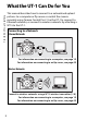
What the UT-1 Can Do for You What the UT-1 Can Do for You This manual describes how to connect to a network and upload pictures to a computer or ftp server or control the camera remotely using Camera Control Pro 2. Use the UT-1 to connect to Ethernet networks, or connect to wireless networks by attaching a WT-5 to the UT-1. Connecting to a Network Ethernet Networks For information on connecting to a computer, see page 19. For information on connecting to an ftp server, see page 49.
Network Connections Control the camera remotely using Camera Control Pro 2 (045) What the UT-1 Can Do for You Once a network connection has been established, you can: Upload existing pictures (036) Upload pictures to an ftp server (049) iii
Trademark Information What the UT-1 Can Do for You Mac OS is a trademark of Apple Computer, Inc. Microsoft, Windows, and Windows Vista are registered trademarks of Microsoft Corporation. All other trade names mentioned in this manual or the other documentation provided with this Nikon product are trademarks or registered trademarks of their respective holders.
For Your Safety For Your Safety To prevent damage to your Nikon product or injury to yourself or to others, read the following safety precautions in their entirety before using this equipment. Keep these safety instructions where all those who use the product will read them.
Avoid extended contact For Your Safety Do not remain in contact with the camera, communication unit, battery, or charger for extended periods while the products are on or in use. Parts of the product become hot; leaving the product in direct contact with the skin for extended periods may result in low-temperature burns. Observe proper precautions when handling batteries Batteries may leak or explode if improperly handled.
Notices Notices • No part of the manuals included with this product may be reproduced, transmitted, transcribed, stored in a retrieval system, or translated into any language in any form, by any means, without Nikon’s prior written permission. • Nikon reserves the right to change the specifications of the hardware and software described in these manuals at any time and without prior notice. • Nikon will not be held liable for any damages resulting from the use of this product.
Notice for Customers in the U.S.A. Notices ❏ U.S.A. Federal Communications Commission (FCC) Declaration of Conformity FCC Radio Frequency Interference Statement This equipment has been tested and found to comply with the limits for a Class B digital device, pursuant to Part 15 of the FCC rules. These limits are designed to provide reasonable protection against harmful interference in a residential installation.
Notices for Customers in Canada Notices for Customers in Europe Notices CAUTION : This class B digital apparatus complies with Canadian ICES-003. ATTENTION : Cet appareil numerique de la classe B est conforme a la norme NMB-003 du Canada. ❏ Symbol for Separate Collection in European Countries The following apply only to users in European countries: This symbol indicates that this product is to be collected separately.
Table of Contents What the UT-1 Can Do for You ................................................................................. ii For Your Safety ............................................................................................................... v Notices ............................................................................................................................vii Introduction ........................................................................1 Parts of the UT-1.........
Menu Guide...................................................................... 71 Mode............................................................................................................................... 72 Choose Profile ................................................................................................................................. 72 FTP Registration (Transfer Mode Only)............................................................................
A Background Knowledge This manual assumes basic knowledge of ftp servers and local area networks (LANs). For more information on installing, configuring, and using devices in a network, contact the manufacturer or network administrator. A Illustrations The Nikon D800 and D800 menus are used in this manual for illustrative purposes. Save where otherwise noted, all software and operating system dialogs, messages, and displays are taken from Windows 7 Ultimate or Mac OS X.
Introduction Thank you for your purchase of a UT-1 communication unit for compatible Nikon digital cameras. Please read this manual thoroughly and keep it where all those who use the product can read it. The following symbols and conventions are used throughout this manual: D This icon marks cautions, information that should be read before use to prevent damage to the product. A This icon marks notes, information that should be read before using the device.
Parts of the UT-1 Parts of the UT-1 1 8 7 2 9 6 14 3 10 4 11 5 1 2 3 4 Peripheral connector cover Peripheral connector Power switch ...................35, 43, 64 Status LEDs ............................... 3, 40 POWER (green/yellow), LINK (green), ERROR (orange) 5 Eyelet for strap 6 USB connector.......................33, 62 2 Introduction 13 12 7 USB connector cover ..........
A Supplied Accessories The following accessories are supplied with the UT-1 (batteries such as the EN-EL15 and the battery chargers such as the MH-25 are not supplied): ❏ ❏ ❏ ❏ ❏ Parts of the UT-1 A The POWER LED When the UT-1 is on, the POWER LED glows green to indicate that the battery is fully charged or that an AC adapter is connected. At battery levels below 10%, it will flash green to warn that the battery requires charging.
A Parts of the UT-1 Attaching the UT-1 The UT-1 can be mounted on a tripod or the camera accessory shoe. To mount the UT-1 on the camera when a flash unit or other accessory is mounted on the accessory shoe, use an optional SK-7 bracket. To mount the UT-1 on the camera accessory shoe: 1 Remove the accessory shoe cover. 2 Slide the UT-1 onto the accessory shoe. 3 Tighten the locking screw.
A Parts of the UT-1 USB Cable Gaskets and Connector Covers The USB cable gaskets and connector covers prevent accidental disconnections. Attach as shown below. Camera When connecting the USB cable to a D4, attach the optional UF-1 connector cover as shown. When connecting the USB cable to a D800 or D800E, attach the supplied UF-3 cable cover as shown. UT-1 When connecting the USB cable to the UT-1, attach the supplied UF3-RU14 cable gasket as shown.
Supported Modes Supported Modes The UT-1 connects the camera to Ethernet and, with the addition of an optional WT-5 wireless transmitter, wireless networks. Photographs on the camera can then be transmitted to a computer ftp server and the camera controlled remotely from a computer. The UT-1 supports the following modes: Mode Host Description See Upload new photographs or Computer Transfer mode existing photographs and movies 033, 62 or ftp server to host.
A A Ethernet Connection The camera can not connect to a wireless LAN when an Ethernet cable is connected. Before connecting to a wireless LAN, turn the UT-1 off and disconnect the Ethernet cable. No adjustments to wireless LAN settings are required when the camera is connected to a LAN by an Ethernet cable. Supported Modes FTP Servers Servers can be configured using standard ftp services available with supported operating systems, such as IIS (Internet Information Services).
Connecting the WT-5 Supported Modes / Connecting the WT-5 The UT-1 can be used in combination with the optional WT-5 wireless transmitter to connect to wireless LANs. The WT-5 connects as described below. 1 2 3 Open the UT-1 peripheral connector cover. Fully insert the WT-5 connector into the UT-1 peripheral connector. Rotate the locking wheel to lock the WT-5 in place. A D4 Cameras Even when connected to a WT-5, the UT-1 functions as a WT-4 wireless transmitter.
Workflow 1 Set up the UT-1 and install software (02). 1-1 Preparing the UT-1 1-2 Installing the Wireless Transmitter Utility Workflow When using the UT-1 for the first time, follow the steps below to set up the UT-1, install the required software and upload pictures to the computer. 2 Upload pictures. Uploading Pictures to a Host Computer (019). 2-1 Copying Network Profiles to the Camera 2-2 Connecting the UT-1 2-3 Uploading Images Uploading Pictures to an ftp Server (049).
Preparing the UT-1 Preparing the UT-1 Inserting the Battery To prevent loss of power during setup or upload, use a fullycharged battery or an optional AC adapter. The UT-1 takes one EN-EL15 rechargeable Li-ion battery; other batteries can not be used. 1 2 3 Slide (q) and open (w) the batterychamber cover. Insert the battery in the orientation shown. For safety precautions and information on charging the battery, see the battery and charger manuals. Close the battery-chamber cover.
A A Stand-By Mode When disconnected from the camera, the UT-1 will turn off automatically after the delay chosen for the Auto power off option in the Wireless transmitter menu (093), reducing the drain on the battery. Preparing the UT-1 Removing the Battery Being careful not to drop the battery, open the battery-chamber cover and remove the battery as shown at right.
Connecting the Adapter 1 Insert the power connector. Preparing the UT-1 Open the UT-1 battery-chamber (qw) and power connector (e) covers and then insert the EP-5B power connector in the orientation shown (r). Position the power connector so that it passes through the power connector slot (t) and close the battery-chamber cover. 2 Connect the AC adapter. Connect the AC adapter power cable to the AC socket on AC adapter (q) and the EP-5B power cable to the DC socket (w).
3 Plug the adapter in. 4 Preparing the UT-1 If the adapter power lamp does not light when the adapter is plugged in, consult a Nikon-authorized service representative. Turn the UT-1 on. Press the power switch for about a second to turn the UT-1 on. When using the AC adapter, be careful that the cords do not become disconnected. Disconnecting the Adapter 1 Unplug the adapter. Turn the UT-1 off and unplug the adapter from the power outlet. 2 Disconnect the EP-5B.
Installing the Wireless Transmitter Utility Installing the Wireless Transmitter Utility This section describes how to install the Wireless Transmitter Utility.
Installing the Wireless Transmitter Utility • To connect to a computer: Pre-installed versions of Windows 7 Home Basic/Home Premium/Professional/ Enterprise/Ultimate (Service Pack 1, 64- and 32-bit versions), Windows Vista Home Basic/Home Premium/ Business/ Enterprise/Ultimate (Service Pack 2, 64- and 32-bit versions), Windows XP Home Edition/ Professional (Service Pack 3, 32-bit version only), or 2 OS Mac OS X version 10.6.8 or 10.7.4 (Intel CPUs only).
❏ Installing Software Installing the Wireless Transmitter Utility Before connecting to a network, install the Wireless Transmitter Utility. The Wireless Transmitter Utility is required for pairing in image transfer and PC modes and can be used to create network profiles. Before installing the software, confirm that your computer meets the system requirements on page 14. Be sure to update to the latest versions of the camera and wireless transmitter firmware and the Wireless Transmitter Utility.
3 Start the installer. 4 Windows Mac OS Click Next Click Continue Installing the Wireless Transmitter Utility Click Next (Windows) or Continue (Mac OS) and follow the on-screen instructions. Exit the installer. Click OK (Windows) or Close (Mac OS) when installation is complete.
Installing the Wireless Transmitter Utility 18 Introduction
Using the UT-1 with a Computer The UT-1 can be used in the following modes (thumbnail select and printer modes are not supported): • Transfer mode: Upload images to a computer. • PC mode: Control the camera from a computer using Camera Control Pro 2 (available separately). The workflow for each of these modes is shown below. 1 Copying Network Profiles to the Camera (020). 2Upload pictures. Uploading Pictures to a Host Computer (033–41). 2-1 Connecting the UT-1 2-2 Uploading Images PC Mode (042–47).
Copying Network Profiles to the Camera Copying Network Profiles to the Camera Before copying network profiles, confirm that the computer is running and the user is logged in. 1 Connect the USB cable supplied with the camera. 2 Turn the camera on. 3 Start the Wireless Transmitter Utility. Power switch • Windows: Double-click the Wireless Transmitter Utility icon on the desktop. • Mac OS X: Click the Wireless Transmitter Utility icon in the Dock.
4 Select WT-4 and click Next (note that you should select WT-4 even when the UT-1 is connected to a WT-5 wireless transmitter). Using the UT-1 with a Computer Copying Network Profiles to the Camera 5 The dialog shown below will be displayed; click Next.
6 Select Add/Edit profiles and click Next.
A Using the UT-1 with a Computer Copying Network Profiles to the Camera The “Select Action” Dialog The other options in the “Select Action” dialog are described below. • Change password: The dialog shown at right will be displayed. By default, no password is required to change device profiles using the Wireless Transmitter Utility. A password can be added by selecting Change password. If the camera is later connected to a different computer, a password prompt will be displayed.
7 Select Add new profile and click Next.
8 Using the UT-1 with a Computer Copying Network Profiles to the Camera Enter the following information and click Next: • Profile name: Enter a name of up to 16 characters. • Connection type: Choose Computer. • Interface type: Choose Wireless & Ethernet for networks that include wireless; if you will not be connecting to a wireless network, select Ethernet only and proceed to Step 11.
9 Select Manual setup and click Next.
A Copying Network Profiles to the Camera “Automatic Setup” Choose Automatic setup (recommended) when using a new network for the first time. The following dialog will be displayed; select Ad hoc, or select Infrastructure network (recommended) and choose a network from the pull-down menu. Click Next to proceed to Step 11 (030). The Automatic setup (recommended) option can not be used with existing network profiles, third-party wireless LAN adapters, networks using static IP addresses, or Mac OS X.
10 Enter the following information and click Next. Copying Network Profiles to the Camera • Network name (SSID): Enter a network name or choose from a list of existing networks. Do not change the name if it is supplied automatically. • Communication mode: Select Infrastructure or Ad-hoc. • Channel: Select a channel (ad hoc only; in infrastructure mode, the UT-1 will choose the channel automatically).
Copying Network Profiles to the Camera 29 Using the UT-1 with a Computer
11 If the network is configured to supply IP addresses automatiCopying Network Profiles to the Camera cally using a DHCP server or Auto IP, select Obtain IP address automatically and click Next. Otherwise remove the check from this option and enter the following information before clicking Next: • Obtain IP address automatically: Select this option if the network is configured to supply IP addresses automatically. If the network does not include a DHCP server, addresses will be supplied by Auto IP.
12 Confirm that settings are correct and click Next. Using the UT-1 with a Computer Copying Network Profiles to the Camera 13 Select Finish wizard and click Next.
14 Turn the camera off and disconnect the USB cable. Copying Network Profiles to the Camera The network profile has now been copied to the camera. Proceed to “Uploading Pictures to a Host Computer” (033) or “PC Mode” (042).
Connecting the UT-1 1 2 3 Turn the camera off and insert the memory card containing the pictures to be sent (if the camera is equipped with multiple memory card slots, the card can be inserted into any slot). 16GB Before connecting the UT-1, confirm that the host computer is running and the user is logged in. Open the UT-1 USB connector cover and connect the USB cable from the UT-1 to the camera USB connector (for more information on connecting USB cables to the camera, see the camera manual).
4 Uploading Pictures to a Host Computer / Connecting the UT-1 5 6 Turn the camera on. Power switch Select Transfer mode for the Wireless transmitter > Mode option in the camera setup menu (072). A list of available connection profiles will be displayed. Highlight the desired profile and press J. A Viewing Profile Information Press the camera L (?) button to view information on the selected profile. 7 Select Wireless transmitter > Transfer settings and adjust settings as described on pages 89–90.
8 Power switch Confirm that the selected profile is displayed in green in the top level of the wireless transmitter menu. For information on what to do if an error is displayed, see “Troubleshooting” (0119). Using the UT-1 with a Computer Uploading Pictures to a Host Computer / Connecting the UT-1 9 Press the power switch for about a second to turn the UT-1 on.
Uploading Images Uploading Pictures to a Host Computer / Uploading Images 1 Press the K button to view pictures on the memory card. Display the first picture to be sent in single-image playback or highlight it in the thumbnail list. 2 Press J (D800 and D800E), press the center of the multi selector while pressing J (D4), or press J while pressing the BKT button (D7000). The image will be marked with a white “send” icon and transmission will begin immediately.
3 Power switch ❏ Interrupting Transmission To cancel transmission of images marked with a white “send” icon or green “sending” icon, select the images during playback and use the controls described in Step 2 on page 36. The icon will be removed.
A Loss of Signal Transmission may be interrupted if the signal is lost (040). Transmission can be resumed by turning the UT-1 off and then on again. Uploading Pictures to a Host Computer / Uploading Images A Turning the Camera Off “Send” marking will be saved if the camera or UT-1 is turned off while transmission is in progress. Transmission of images marked with a “send” icon will resume when the camera or UT-1 is turned on.
❏ Transfer Status During playback, the status of images selected for upload is shown as follows: Images that have been selected for upload are marked with a white a icon. b: “Sending” A green b icon is displayed during upload. c: “Sent” Images that have been uploaded successfully are marked with a blue c icon.
❏ Network Status Uploading Pictures to a Host Computer / Uploading Images The status of the link between the host and the UT-1 is shown by the status LEDs and by the display in the top level of the wireless transmitter menu. The Status LEDs The POWER LED lights when the UT-1 is on. Signal quality is shown by the LINK LED: the faster the LED flashes, the better the signal and the faster data can be transmitted. The ERROR LED flashes to show that an error has occurred.
The Status Display Network status can also be viewed in the top level of the wireless transmitter menu. Battery level: A fivelevel display showing the charge state of the battery in the UT-1. Signal strength: Wireless signal strength. Ethernet connections are shown by d. Using the UT-1 with a Computer Uploading Pictures to a Host Computer / Uploading Images e, f: The estimated time required to send the remaining images. Status area: The status of the connection to the host.
PC Mode PC Mode / Connecting to the Computer In PC mode, a camera equipped with a UT-1 can be controlled over a wireless or Ethernet network from a computer running Camera Control Pro 2 (available separately) and photographs saved directly to the computer hard disk instead of the camera memory card (movies are still recorded to the memory card and can consequently only be recorded when a memory card is inserted in the camera).
3 5 Power switch PC Mode / Connecting to the Computer 4 Turn the camera on. Select PC mode for the Wireless transmitter > Mode option in the camera setup menu (072). A list of available connection profiles will be displayed. Highlight the desired profile and press J. A Viewing Profile Information Press the camera L (?) button to view information on the selected profile. 6 Press the power switch for about a second to turn the UT-1 on.
7 PC Mode / Connecting to the Computer When a connection is established, the network name will be displayed in green in the top level of the wireless transmitter menu. For information on what to do if an error is displayed, see “Troubleshooting” (0119).
Controlling the Camera 3 4 Complete the steps in “Connecting to the Computer” (042). Start Camera Control Pro 2 on the host computer and confirm that “PC” is displayed in the camera control panel. Control the camera as described in the Camera Control Pro 2 manual or online help. When transfer is complete, press the power switch for about a second to turn the UT-1 off and then disconnect the USB cable.
❏ Network Status PC Mode / Controlling the Camera The status of the link between the host and the UT-1 is shown by the status LEDs and by the display in the top level of the wireless transmitter menu. The Status LEDs The POWER LED lights when the UT-1 is on. Signal quality is shown by the LINK LED: the faster the LED flashes, the better the signal and the faster data can be transmitted. The ERROR LED flashes to show that an error has occurred.
The Status Display Network status can also be viewed in the top level of the wireless transmitter menu. Battery level: A fivelevel display showing the charge state of the battery in the UT-1. Signal strength: Wireless signal strength. Ethernet connections are shown by d. Using the UT-1 with a Computer PC Mode / Controlling the Camera Status area: The status of the connection to the host. The host name is displayed in green when a connection is established.
PC Mode 48 Using the UT-1 with a Computer
Uploading Pictures to an ftp Server Follow the steps below to upload pictures to an ftp server over wireless or Ethernet networks. 1 Copying Network Profiles to the Camera (050) 2 Connecting to the ftp Server (062) 3 Uploading Images (065) D Before Connecting Configure the server before connecting. Servers can be configured using standard ftp services available with supported operating systems, such as IIS (Internet Information Services).
Copying Network Profiles to the Camera Copying Network Profiles to the Camera Before copying network profiles, confirm that the computer is running and the user is logged in. 1 Connect the USB cable supplied with the camera. 2 Turn the camera on. 3 Power switch Start the Wireless Transmitter Utility. • Windows: Double-click the Wireless Transmitter Utility icon on the desktop. • Mac OS X: Click the Wireless Transmitter Utility icon in the Dock.
4 Select WT-4 and click Next (note that you should select WT-4 even when the UT-1 is connected to a WT-5 wireless transmitter). Uploading Pictures to an ftp Server Copying Network Profiles to the Camera 5 The dialog shown below will be displayed; click Next.
Copying Network Profiles to the Camera 6 Select Add/Edit profiles and click Next. 7 Select Add new profile and click Next.
8 Uploading Pictures to an ftp Server Copying Network Profiles to the Camera Enter the following information and click Next: • Profile name: Enter a name of up to 16 characters. • Connection type: Choose FTP Server. • Interface type: Choose Wireless & Ethernet for networks that include wireless; if you will not be connecting to a wireless network, select Ethernet only and proceed to Step 11.
9 Select Manual setup and click Next.
A Copying Network Profiles to the Camera “Automatic Setup” Choose Automatic setup when using a new network for the first time. The following dialog will be displayed; select Ad hoc, or select Infrastructure network (recommended) and choose a network from the pull-down menu. Click Next to proceed to Step 11 (058). The Automatic setup (recommended) option can not be used with existing network profiles, third-party wireless LAN adapters, networks using static IP addresses, or Mac OS X.
10 Enter the following information and click Next. Copying Network Profiles to the Camera • Network name (SSID): Enter a network name or choose from a list of existing networks. Do not change the name if it is supplied automatically. • Communication mode: Select Infrastructure or Ad-hoc. • Channel: Select a channel (ad hoc only; in infrastructure mode, the UT-1 will choose the channel automatically).
Copying Network Profiles to the Camera 57 Uploading Pictures to an ftp Server
11 Remove the check from Obtain IP address automatically Copying Network Profiles to the Camera and enter the following information. Click Next to proceed when entry is complete. • IP address: Enter an IP address for the UT-1. • Subnet mask: Enter a subnet mask for the UT-1. • Default gateway: If the network requires a gateway address, select this option and enter the address supplied by the network administrator.
12 Enter ftp settings and click Next. Uploading Pictures to an ftp Server Copying Network Profiles to the Camera • FTP server: Enter the URL or IP address of the ftp server. • FTP server port: Enter the port number for the ftp server. • FTP path: Choose the folder to which pictures will be uploaded. If no path is specified, pictures will be uploaded to the home folder. • Anonymous login: Select this option for anonymous login, or leave this option unchecked to supply a User ID and Password.
13 Confirm that settings are correct and click Next. Copying Network Profiles to the Camera 14 Select Finish wizard and click Next.
15 Press the power switch for about a second to turn the camera off and disconnect the USB cable. Uploading Pictures to an ftp Server Copying Network Profiles to the Camera The network profile has now been copied to the camera. Proceed to “Connecting to the ftp Server” (062).
Connecting to the ftp Server 1 2 3 Turn the camera off and insert the memory card containing the pictures to be sent (if the camera is equipped with multiple memory card slots, the card can be inserted into any slot). 16GB Connecting to the ftp Server Before connecting the UT-1, confirm that the host computer is running and the user is logged in.
4 6 Power switch Select Transfer mode for the Wireless transmitter > Mode option in the camera setup menu (072). Connecting to the ftp Server 5 Turn the camera on. A list of available connection profiles will be displayed. Highlight the desired profile and press J. A Viewing Profile Information Press the camera L (?) button to view information on the selected profile. A Editing ftp Server Profiles To edit the ftp server profile, press the camera W button after turning on the UT-1.
7 Connecting to the ftp Server 8 9 Select Wireless transmitter > Transfer settings and adjust settings as described on pages 89–90. Press the power switch for about a second to turn on the UT-1. Confirm that the selected profile is displayed in green in the top level of the wireless transmitter menu. For information on what to do if an error is displayed, see “Troubleshooting” (0119).
Uploading Images Press the K button to view pictures on the memory card. Display the first picture to be sent in single-image playback or highlight it in the thumbnail list. 2 Press J (D800 and D800E), press the center of the multi selector while pressing J (D4), or press J while pressing the BKT button (D7000). The image will be marked with a white “send” icon and transmission will begin immediately. During upload, images are marked with a green “sending” icon.
3 Uploading Images Press the power switch for about a second to turn the UT-1 off, then disconnect the USB cable and UT-1. The destination folder can be selected using the Wireless Transmitter Utility (023, 59). Power switch ❏ Interrupting Transmission To cancel transmission of images marked with a white “send” icon or green “sending” icon, select the images during playback and use the controls described in Step 2 on page 65. The icon will be removed.
❏ Transfer Status During playback, the status of images selected for uploaded is shown as follows: Images that have been selected for upload are marked with a white a icon. Uploading Images a: “Send” b: “Sending” A green b icon is displayed during upload. c: “Sent” Images that have been uploaded successfully are marked with a blue c icon. A Loss of Signal Transmission may be interrupted if the signal is lost (068). Transmission can be resumed by turning the UT-1 off and then on again.
❏ Network Status Uploading Images The status of the link between the host and the UT-1 is shown by the status LEDs and by the display in the top level of the wireless transmitter menu. The Status LEDs The POWER LED lights when the UT-1 is on. Signal quality is shown by the LINK LED: the faster the LED flashes, the better the signal and the faster data can be transmitted. The ERROR LED flashes to show that an error has occurred.
The Status Display Network status can also be viewed in the top level of the wireless transmitter menu. Battery level: A fivelevel display showing the charge state of the battery in the UT-1. Uploading Images e, f: The estimated time required to send the remaining images. Status area: The status of the connection to the host. The host name is displayed in green when a connection is established.
Uploading Images 70 Uploading Pictures to an ftp Server
Menu Guide This section describes the settings available for the Wireless transmitter option in the camera setup menu when the UT-1 is connected. Menu item Mode Choose Profile FTP Registration (Transfer Mode Only) Editing ftp Profiles (for Connection to ftp Servers Only) Transfer Settings Auto Send Delete After Send? Send File As Send Folder Deselect All? Print Device Info Battery Info MAC Address Firmware Version Device Settings Auto Power Off Format Transmitter’s Memory Pg.
Mode Mode / Choose Profile Choose from transfer (033) and PC (042) modes; thumbnail select and print modes are not supported. Selecting either option displays a profile list showing the connections available in the selected mode. Choose Profile Selecting an option from the Mode menu displays a profile list showing the connections available in the selected mode. The UT-1 can store a total of up to nine host and server profiles. To delete a profile, highlight it in the profile list and press the O button.
FTP Registration (Transfer Mode Only) Editing ftp Profiles (for Connection to ftp Servers Only) To edit an ftp server profile, highlight it in the profile list in transfer mode and press the W button. Choose the settings to be edited from Wireless, TCP/IP, and FTP, or select Done to save changes and return to the profile list. Only ftp server profiles can be edited in this fashion; to edit other profiles, use the Wireless Transmitter Utility.
❏ Wireless Mode / Editing ftp Profiles (for Connection to ftp Servers Only) / Wireless This option contains settings for connection to a wireless network and is only displayed if the interface type for the selected profile is Wireless & Ethernet. The wireless menu has two pages of options; to scroll between pages, press the multi selector up or down. Wireless Menu, Page 1/2 SSID: A BSS- or ESS-ID is required for connection to a wireless LAN adapter or access point.
Channel * 1 Return to the wireless menu (1/2). * Not required if Infrastructure is selected for Communication mode. Authentication: Choose the type of authentication used by the computer or access point. The camera supports WPA-PSK, WPA2-PSK, open system, and shared key authentication. WPA-PSK and WPA2-PSK are available only in infrastructure mode. Menu Guide Mode / Editing ftp Profiles (for Connection to ftp Servers Only) / Wireless 2 Choose a channel.
Wireless Menu, Page 2/2 Encryption Mode / Editing ftp Profiles (for Connection to ftp Servers Only) / Wireless 1 Highlight an encryption method. A Encryption The type of encryption available depends on the option selected for Authentication (028, 75): •Open: No encryption, WEP •Shared: WEP •WPA-PSK: TKIP, AES •WPA2-PSK: AES 2 3 Return the to wireless menu (2/2). Highlight an encryption key. Skip Steps 3–5 if No encryption was selected in Steps 1–2.
4 Return to the wireless menu (2/2). Key index: In infrastructure networks that use WEP encryption, choose the key index used by the host or access point. 1 2 Choose an index. Mode / Editing ftp Profiles (for Connection to ftp Servers Only) / Wireless 5 Edit the encryption key: • Base 16: Enter the key as described on page 73. 64-bit keys require 10 digits, 128-bit keys 26 digits, TKIP and AES keys 64 digits. • ASCII: Enter the key as described on page 26.
❏ TCP/IP Mode / Editing ftp Profiles (for Connection to ftp Servers Only) / TCP/IP Adjust TCP/IP settings as described on the following pages. The TCP/IP menu has two pages of options; to scroll between pages, press the multi selector up or down. TCP/IP Menu, Page 1/2 Obtain automatically: Highlight this option and press the multi selector right to toggle it on (M) or off. Turn this option on if the wireless network is configured to supply an IP address automatically by DHCP server or Auto IP.
4 Exit to the TCP/IP menu (1/2). If a sub-net mask is required, proceed to Step 5. Highlight Mask. 6 Enter edit mode. 7 Choose a sub-net mask. 8 Exit to the TCP/IP menu (1/2).
TCP/IP Menu, Page 2/2 Mode / Editing ftp Profiles (for Connection to ftp Servers Only) / TCP/IP Use gateway: Highlight this option and press the multi selector right to toggle it on (M) or off. If the network requires a gateway address, turn this option on and enter the address supplied by the network administrator as described below. 1 Highlight Address. 2 Enter edit mode. 3 4 Press the multi selector left or right to select, up or down to change. Return to the TCP/IP menu (2/2).
1 Highlight Address. 2 Enter edit mode. 3 4 Mode / Editing ftp Profiles (for Connection to ftp Servers Only) / TCP/IP Enable DNS: Highlight this option and press the multi selector right to toggle it on (M) or off. If a Domain Name Server (DNS) exists on the network, turn this option on and enter the address supplied by the network administrator as described below. Press the multi selector left or right to select, up or down to change. Return the to TCP/IP menu (2/2).
❏ FTP Mode / Editing ftp Profiles (for Connection to ftp Servers Only) / FTP Adjust ftp settings as described on the following pages. The ftp menu has three pages of options; to scroll between pages, press the multi selector up or down. FTP Menu, Page 1/3 Server 1 Highlight Address. 2 Display the text entry dialog. 3 4 Enter a server address (required; 073). Return to the ftp menu (1/3).
Highlight Folder. 6 Display the text entry dialog. 7 Mode / Editing ftp Profiles (for Connection to ftp Servers Only) / FTP 5 Enter the destination folder name (073). 8 Return to the ftp menu (1/3). 9 Highlight Port.
10 Enter edit mode. Mode / Editing ftp Profiles (for Connection to ftp Servers Only) / FTP 11 Press the multi selector left or right to select, up or down to change. 12 Return to the ftp menu (1/3). PASV mode: Highlight this option and press the multi selector right to toggle PASV mode on (M) or off.
FTP Menu, Page 2/3 1 Highlight User ID. 2 Display the text entry dialog. 3 Enter a user name (073). 4 Return to the ftp menu (2/3). Mode / Editing ftp Profiles (for Connection to ftp Servers Only) / FTP Anonymous login: Highlight this option and press the multi selector right to toggle it on (M) or off. Turn this option on for anonymous login, off to enter a user name and password as described below.
Mode / Editing ftp Profiles (for Connection to ftp Servers Only) / FTP 5 Highlight Password. 6 Display the text entry dialog. 7 Enter a password (073). 8 Return to the ftp menu (2/3).
FTP Menu, Page 3/3 1 Highlight Address. 2 Display the text entry dialog. 3 4 Mode / Editing ftp Profiles (for Connection to ftp Servers Only) / FTP Use proxy server: Highlight this option and press the multi selector right to toggle it on (M) or off. If a proxy server is required for ftp, turn this option on and enter an address and port number as described below. Enter a proxy server address (073). Return to the ftp menu (3/3).
Mode / Editing ftp Profiles (for Connection to ftp Servers Only) / FTP 5 Highlight Port. 6 Enter edit mode. 7 8 Press the multi selector left or right to select, up or down to change. Return to the ftp menu (3/3).
Transfer Settings (Transfer Mode Only) The following settings are available in transfer mode: Transfer Settings / Auto Send Auto Send Choose whether to upload photographs to the server as they are taken. Option Description Photos are uploaded immediately after being recorded to camera memory On card. * Be sure memory card is inserted in camera before shooting. Photos are not automatically uploaded Off as they are taken. Photos can be (default) selected for transmission when camera is in playback mode.
Send File As Transfer Settings / Send File As When uploading NEF + JPEG images to an ftp server, choose whether to send both NEF (RAW) and JPEG files or only the JPEG files. Option NEF (RAW) + JPEG (default) JPEG only Description Upload both NEF (RAW) and JPEG files. Upload JPEG files only. Send Folder Upload all files in selected folders (including those already marked as “sent”). Deselect All? Select Yes to remove “send,” “sending,” and “sent” marking from all images on the memory card.
Print (Print Mode Only) The UT-1 does not support this option.
Device Info Device Info / Battery Info This menu displays the following information about the UT-1. This option is only available when the UT-1 is connected to the camera via USB and the UT-1 is on. On the D4, the options in the D800 Device info and Device settings menus can be found under Network > Device info and settings. Battery Info Displays information on the battery inserted in the UT-1. The Charging life display shows battery age; replace the battery when Charging life reaches 4.
Device Settings Auto Power Off Set the time delay until the UT-1 power automatically turns off after the USB connection between the camera and UT-1 is terminated. Device Settings / Auto Power Off Format the transmitter’s internal memory and choose the delay before the UT-1 turns off automatically. This option is only available when the UT-1 is connected to the camera via USB and the UT-1 is on.
Device Settings 94 Menu Guide
Appendices Creating an FTP Server Images can be uploaded to ftp servers created using the standard ftp services included with Windows 7 (Professional/Enterprise/ Ultimate), Windows Vista (Ultimate/Business/Enterprise), Windows XP Professional, and Mac OS X. Under Windows, Internet Information Services (IIS) are required to configure ftp servers (installation instructions are available from Microsoft).
Windows 7 1 Go to Network and Sharing Center. Creating an FTP Server Click Start > Control Panel > Network and Internet > Network and Sharing Center. 2 Display the network adapter list. Click Change adapter settings. 3 Open the network properties dialog. If you are connecting via Ethernet, right-click Local Area Connection and select Properties. If connection is via a wireless LAN adapter, select Properties in the context menu for Wireless Network Connection.
4 Display TCP/IP settings. 5 Creating an FTP Server Select Internet Protocol Version 4 (TCP/IPv4) and click Properties. Enter an IP address and subnet mask. Enter an IP address and subnet mask for the ftp server and click OK.
6 Close the network properties dialog. Click Close. Creating an FTP Server 7 Open Administrative Tools. Click Start > Control Panel > System and Security > Administrative Tools.
8 Open the IIS manager. Double-click Internet Information Services (IIS) Manager. Creating an FTP Server 9 Select Add FTP Site…. Right-click the computer user name and select Add FTP Site….
10 Enter site information. Creating an FTP Server Name the site and choose the path to the folder that will be used for ftp upload. Click Next to proceed. A Anonymous Login To allow anonymous login, select a folder in the user’s public folder as the content directory.
11 Choose binding and SSL options. Appendices Creating an FTP Server Select the IP address entered in Step 5, note the port number, select Start FTP site automatically, and check No SSL. Click Next to proceed.
12 Choose authentication options. Creating an FTP Server Adjust settings as described below and click Finish.
Windows Vista 1 Display network connections. 2 Open the network properties dialog. If you are connecting via Ethernet, right-click Local Area Connection and select Properties. If connection is via a wireless LAN adapter, select Properties in the context menu for Wireless Network Connection. 3 Creating an FTP Server Click Start > Control Panel > Network and Internet Settings > Network Connections > Manage Network Connections. Click Allow.
4 Display TCP/IP settings. Creating an FTP Server Select Internet Protocol Version 4 (TCP/IPv4) and click Properties.
5 Enter an IP address and subnet mask. 6 Creating an FTP Server Enter an IP address and subnet mask for the ftp server and click OK. Open Administrative Tools. Click Start > Control Panel > System and Maintenance > Administrative Tools.
7 Open the IIS manager. Creating an FTP Server Double-click Internet Information Services (IIS) 6.0 Manager. 8 Click Allow. A “User Account Control” dialog will be displayed; click Allow.
9 Display ftp site properties. Right-click Default FTP Site and select Properties.
10 Select the address and port number. Creating an FTP Server Select the IP address entered in Step 5 and enter a TCP port number.
11 Choose a home directory. Appendices Creating an FTP Server Open the Home Directory tab and select A directory located on this computer. The root directory for images uploaded to the ftp server is listed in the Local path text box; choose a folder and select Read, Write, and Log visits. Click OK to close the properties dialog.
Windows XP 1 Display network connections. Creating an FTP Server Click Start > Control Panel > Network and Internet Settings > Network Connections. 2 Open the network properties dialog. If you are connecting via Ethernet, right-click Local Area Connection and select Properties. If connection is via a wireless LAN adapter, select Properties in the context menu for Wireless Network Connection. 3 Display TCP/IP settings. Select Internet Protocol (TCP/IP) and click Properties.
4 Enter an IP address and subnet mask. 5 Creating an FTP Server Enter an IP address and subnet mask for the ftp server and click OK. Open Internet Information Services. Click Start > Control Panel > System and Maintenance > Administrative Tools and open the Internet Information Services console.
6 Display ftp site properties. Right-click Default FTP Site and select Properties. Creating an FTP Server 7 Select the address and port number. Select the IP address entered in Step 4 and enter a TCP port number.
8 Choose a home directory. Appendices Creating an FTP Server Open the Home Directory tab and select a directory located on this computer. The root directory for images uploaded to the ftp server is listed in the Local path text box; choose a folder and select Read, Write, and Log visits. Click OK to close the properties dialog.
Mac OS X 10.6 1 Display network settings. Creating an FTP Server Open System Preferences and click Network. 2 Adjust network settings. Click the type of network you will use to connect to the server, enter an IP address, and note the subnet mask. Click Show All to return to the main System Preferences panel when settings are complete. 3 Click Sharing.
4 Display file sharing options. Select File Sharing and click Options. Creating an FTP Server 5 Turn ftp file sharing on. Select Share files and folders using ftp.
Creating ftp Profiles Using Camera Menus Creating ftp Profiles Using Camera Menus In transfer mode, the camera menus can be used in place of the Wireless Transmitter Utility to create ftp profiles. Before creating an ftp profile with the camera menus, connect the UT-1. To prevent unexpected loss of power, be sure the battery is fully charged or use an optional EP-5B power connector and EH-5b AC adapter.
3 5 6 Power switch Creating ftp Profiles Using Camera Menus 4 Press the power switch for about a second to turn the UT-1 on. Select Transfer mode for Wireless transmitter > Mode (072). A profile list will be displayed showing the connections available in transfer mode. Highlight FTP registration and press the multi selector to the right. Note a new ftp profile can not be created if the camera already contains nine profiles; if necessary, delete a profile using the O button.
Creating ftp Profiles Using Camera Menus Interface type: The dialog shown at right will be displayed. Highlight one of the following options and press the J button to return to the registration dialog. Option Description Wireless & Ethernet Connect via wireless and/ (default) or Ethernet. Ethernet only Connect via Ethernet only. Wireless: If Wireless & Ethernet is selected for Interface type, select this option to adjust wireless settings as described in the Menu Guide (074–77).
Troubleshooting Problem Wireless transmitter option not available. The Device info, and Device settings menus cannot be selected. Excessive radio interference. Confirm that the UT-1 is connected and on. Page 35, 43, 64 10, 92 33, 42, 62 Troubleshooting “POWER” LED does not light. Solution • Turn the UT-1 on. • Confirm that the battery is inserted and fully charged. Confirm that the UT-1 is connected and on. 33, 42, 62 Adjust the position of the wireless — access point or host computer.
Troubleshooting Problem Transfer interrupted before all photographs are sent. USB cable disconnected during transmission. 120 Appendices Solution Transfer will resume if UT-1 is turned off and then on again. Reconnect the USB cable. Do not turn the camera off.
Specifications Ethernet Standards Data rates Port Wireless (WT-5) IEEE 802.3u (100 base-TX)/IEEE 802.3 (10 base-T) 10/100 Mbps with auto detect 100 base-TX/10 base-T (AUTO-MDIX) Specifications ❚❚ Communication Unit UT-1 WT-5/WT-5A/WT-5B/WT-5C: 802.11a/b/g/n WT-5D: 802.11b/g/n IEEE802.11a: OFDM Communications IEEE802.11g: OFDM protocols IEEE802.11b: DSSS IEEE802.
Wireless (WT-5) Specifications IEEE 802.11a/g: 6, 9, 12, 18, 24, 36, 48 and 54 Mbps IEEE 802.11b: 1, 2, 5.5 and 11 Mbps Data rates † IEEE 802.11n-HT20: 72 Mbps maximum IEEE 802.11n-HT40:150 Mbps maximum Authentication: Open system, shared key, WPA-PSK, Security WPA2-PSK Encryption: 128/64 bit WEP, TKIP, AES Access protocols Infrastructure, ad hoc Data transfer protocols PTP-IP, ftp Approximately 1.9 W maximum (UT-1 only) Power consumption Approximately 2.
A Network No. of shots uploaded Battery life Wireless (802.11n) 8000 300 min. (5 hr.) Specifications Battery Life The length of time batteries can be used and the number of shots that can be uploaded before recharging varies with the condition of the batteries, signal strength, and how camera and UT-1 are used. The following measurements were performed using a fully-charged EN-EL15 battery (1900 mAh) at a temperature of 23 °C (73.
Index Index Symbols a: “Send” ............................................. 39, 67 b: “Sending”....................................... 39, 67 c: “Sent”............................................... 39, 67 A Ad-hoc.......................................................... 74 Auto power off ................................... 11, 93 Auto send.................................................... 89 B Battery info ................................................. 92 BSS-ID ....................................
Index Wireless............................................... 74, 118 Wireless LAN access point .............................................74 Wireless transmitter .................................71 Wireless Transmitter Utility .....
126
No reproduction in any form of this manual, in whole or in part (except for brief quotation in critical articles or reviews), may be made without written authorization from NIKON CORPORATION.