No reproduction in any form of this manual, in whole or in part (except for brief quotation in critical articles or reviews), may be made without written authorization from NIKON CORPORATION.
Thank you for your purchase of an WR-1 wireless remote controller. Read both this manual and the documentation provided with your camera before using the product, and keep these instructions where they will be read by all who use the product. Controller Settings Unless otherwise noted, the explanations in this manual assume that default settings are used.
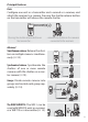
Principal Features Basic Configure one unit as a transmitter and a second as a receiver, and attach the receiver to a camera. Pressing the shutter-release button on the transmitter will release the camera shutter. Pressing the shutter-release button on the transmitter… …releases the shutter on the cameras connected to the receivers. Advanced Simultaneous release: Release the shutters on multiple cameras simultaneously (0 12).
Wireless Regulation Data Trade Name: Model: WR-1 FCC ID: CGJ4149EA IC: 4634A-4149EA Compliance Statement This device complies with Part 15 of the FCC Rules and with RSS-210 of Industry Canada. Operation is subject to the following two conditions: (1) this device may not cause harmful interference, and (2) this device must accept any interference received, including interference that may cause undesired operation.
Notices for Customers in Europe EC Declaration of Conformity Nikon WR-1 Manufacturer: Nikon Corporation A copy of the original DoC for this product as it relates to R&TTE can be found at the following website: http://imaging.nikon.com/support/pdf/ DoC_WR-1.pdf R&TTE Directive This product conforms to the regulations governing radio-frequency devices in the following countries and can not be used in other jurisdictions.
For Your Safety To prevent damage to your Nikon product or injury to yourself or to others, read the following safety precautions in their entirety before using this product. Keep these safety instructions where all those who use the product will read them. The consequences that could result from failure to observe the precautions listed in this section are indicated by the following symbol: This icon marks warnings, information that should be read before using this Nikon product to prevent possible injury.
A Follow the instructions of hospital and airline personnel. This product emits radio frequency radiation that could interfere with medical or navigational equipment. Turn the product off during takeoff and landing and when so directed by airline or hospital staff. A Observe proper precautions when handling batteries. Batteries may leak, rupture, or overheat if improperly handled.
Notices • No part of this manual may be reproduced, transmitted, transcribed, stored in a retrieval system, or translated into any language in any form, by any means, without Nikon’s prior written permission. • Nikon reserves the right to change the specifications of the hardware and software described in this manual at any time and without prior notice. • Nikon will not be held liable for any damages resulting from the use of this product.
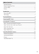
Table of Contents Principal Features .............................................................................................................. i Wireless Regulation Data ...............................................................................................ii For Your Safety ..................................................................................................................iv Notices...................................................................................................
Menus 16 16 Using the Menus ............................................................................................................ 17 SPECIAL ............................................................................................................................. 18 Interval Timer Photography ................................................................................. 18 Release Hold Time ...................................................................................................
Introduction This section offers an overview of product controls and displays. Parts of the WR-1 1 LED (red/green) ...................................9 2 Display .....................................................2 3 Group buttons (A, B, C, D)............... 10 4 SEL (device) button .................11, 24 5 y (illuminator) button ...................3 6 Shutter-release button .................. 10 7 Release.....................................................
The Display 1 2 3 4 5 6 7 8 9 13 12 10 11 Tx/Rx/OFF switch set to Tx (transmitter) 1 2 3 4 5 6 13 12 7 8 11 Tx/Rx/OFF switch set to Rx (receiver) Description 1 If Tx/Rx/OFF switch is set to Tx, a is displayed and unit functions as transmitter; if switch is set to Rx, b is displayed and unit functions as receiver. 0 8 2 Indicates whether unit links to other units via pairing (j) 9, 23 or ID (i). 3 ID mode name. Not displayed in pairing mode. 2 23 4 Displayed when controls are locked.
Description 7 Current channel. 0 8 8 Last three digits of unit serial number (or, if unit has been assigned 1, 23 unit ID, current body number of from #01 to #20). 9 Last three digits of unit serial number (or, if unit has been assigned 25 unit ID, current body number) of selected receiver in each group. 10 Number of receivers in each group (up to 20). 14 11 Currently selected group (A, B, C, or D). 10 12 Wireless signal strength. — 13 Feature selected in transmitter mode.
Inserting Batteries The WR-1 is powered by two AA alkaline or nickel-metal hydride (NiMH) batteries. To insert batteries: 1 Open the battery-chamber cover. Japa E IN MAD Sam pl H1 e ES 104 0400 7A n Unlatch and open the battery-chamber cover. 2 Insert the batteries. Insert two AA batteries in the orientation shown. 3 Close the battery-chamber cover. 4 Japa E IN MAD Sam pl H1 e ES 104 0400 7A n Be sure the cover is securely latched.
A Units Connected to Cameras When connected to a camera (0 6), WR-1 units are powered by the camera; batteries are not required. A Standby Mode If no operations are performed for the length of time selected for STBY p (0 16), transmitters will enter standby and their displays will turn off to save power. Units that are connected to a camera will turn off automatically when the camera is turned off.
Connecting WR-1 Units Connect the units to the cameras they will be used to control. 1 Open the ten-pin terminal cover. Open the terminal cover as shown. Ten-pin terminal 2 Connect the supplied ten-pin or accessory terminal cable. Use the supplied MC-37 cable when connecting receivers to cameras with ten-pin remote terminals, the MC-38 when connecting receivers to cameras with accessory terminals.
A Fixing Units in Place The WR-1 can be mounted on the camera accessory shoe as shown at right. Once the unit is in place, it can be angled as shown at right. To remove the WR-1, angle it as shown in Figure 1 or 2, and then press the release (q) and slide the unit off the accessory shoe (w). The unit can only be removed when angled as shown. Figure 1 Figure 2 If desired, the WR-1 can be mounted on a tripod or an optional SK-7 bracket.
Using the WR-1: The Basics The instructions that follow describe how to control a single camera using two WR-1 units, one functioning as a transmitter and the other as a receiver. Step 1: Position the Tx/Rx/OFF Switches Slide the Tx/Rx/OFF switch for the transmitter to Tx and the switch for the receiver to Rx. The units will turn on and display the information shown below. Tx (transmitter) Rx (receiver) Step 2: Set the Units to the Same Channel Press 1 or 3 to choose from channels 1 to 15.
Step 3: Pair the Units Follow the steps below to pair the units. Units can be paired only with other devices on the same channel. 1 Set the units to pairing mode. Press the MENU button to display the menus, then highlight PAIRING in the LINK MODE menu and press z. Repeat for the second unit. 2 Display the PAIRING menus. Highlight PAIRING and press 2. Repeat for the second unit. 3 Select EXECUTE on both units.
Step 4: Group the Units Each receiver can be placed in any of four groups (A, B, C, and D). A transmitter can then be used to control the different groups separately by selecting the appropriate group before operating the transmitter controls. Transmitters will only control receivers in the selected group. To choose a group, use the group buttons. The group name appears in the display.
A Traffic Level The traffic on each channel can be gauged by pressing 2 for about a second. The traffic level for each channel is shown by an icon; choosing a lowtraffic channel improves performance. Note that the display varies depend- (No icon) ing on when it was last updated; when multiple WR-1 units are used, their No traffic displays will not necessarily show the same traffic levels.
Controlling Multiple Cameras This section describes the ways in which multiple receivers can be used to control more than one camera at a time. Simultaneous Release If the transmitter and receivers are paired (0 9), on the same channel (0 8), and in the same group (0 10), pressing the transmitter shutter-release button all the way down will simultaneously release the shutters on all cameras to which receivers have been attached.
Synchronized Release To synchronize the shutters of one or more remote cameras with the shutter on a master camera, attach the receivers to the remote cameras and the transmitter to the master camera. The master camera must be equipped with a ten-pin remote terminal. 1 Connect the controllers. Connect the transmitter (set to Tx) to the master camera (any camera with a ten-pin remote terminal) and the receivers (set to Rx) to the remote cameras. 2 Configure the controllers.
Groups Remote cameras can be divided into up to four groups (A, B, C, and D). The cameras in each group can be controlled separately by using the transmitter group buttons to select the desired group before pressing the shutter-release button. A B C A Group Size The transmitter shows the number of receivers in the current group.
The WR-R10/WR-T10 WR-1 units can be used with WR-R10 and WR-T10 wireless remote controllers (available separately). WR-R10 WR-R10 WR-T10 WR-R10 WR-A10 WR-1 units must be in pairing mode before they can be paired with WR-R10 or WR-T10 wireless remote controllers; pairing instructions for the WR-1 are identical to those given on page 9, while those for the WR-R10/WR-T10 can be found in the manual provided with the devices.
Menus The menus contain the items listed below. To display the menus, press the MENU button. Item Description LINK MODE Choose whether to link to other units via pairing or ID. BODY NO. Select unit ID (body number) of from #01 to #20 (0 23). Unit IDs are required for ID mode, but also simplify task of organizing units in pairing mode. ID replaces last three digits of serial number in unit display. 16 ID-NAME Enter ID mode name (0 23).
Item Description BATTERY To ensure accuracy of battery level display, select option that matches type of battery inserted in device. Choose from LR6 (AA alkaline) and HR6 (rechargeable AA NiMH). SPECIAL Use transmitter for interval timer photography (INT; 0 18) or choose transmitter release hold time (RHT; 0 20), or configure receiver as relay (RLY; 0 21) or choose receiver release delay (DLY; 0 22). To disable above functions, select DISABLE. VERSION View unit firmware version.
SPECIAL The SPECIAL menu is used to configure transmitters for interval timer photography and to choose the maximum duration for bulb photography, or to configure receivers to relay transmitter commands to a second receiver and to choose the delay before the shutter is released in response to transmitter commands. Interval Timer Photography Configure transmitters to release the shutters of remote cameras automatically at preset intervals. 1 Select SPECIAL on the transmitter.
4 Choose the number of intervals. Highlight NUM OF SHOTS and press 2. The options shown at right will be displayed; press 1 or 3 to choose the number of intervals. Press z to return to the interval timer menu when settings are complete. 5 Choose the starting trigger. Highlight START WITH RELEASE and press 2. Highlight one of the following options and press z. • ON: Interval timer photography starts when the transmitter shutter-release button is pressed.
Release Hold Time Choose how the remote cameras respond when the transmitter shutter-release button is held all the way down. • TIME: The transmitter shutter-release button can be used for long time-exposures; shooting ends automatically after a selected time. • SINGLE SHOOT: Only one picture will be taken regardless of how long the button is pressed. 1 Select SPECIAL on the transmitter. Press the MENU button on the transmitter to display the menus, then highlight SPECIAL and press 2. 2 Select RHT.
Relay Receivers can be configured to relay transmitter commands to another receiver, increasing transmitter range and allowing signals to be transmitted around obstacles. Transmitter Relay Receiver 1 Configure the relay. On the unit that will act as the relay, slide the Tx/Rx/OFF switch to Rx. Press the MENU button to display the menus, then highlight SPECIAL and press 2. Highlight RLY and press z to configure the unit to act as a relay. 2 Configure the remaining units.
Release Delay Choose how long a receiver waits to release the shutter after the transmitter shutter-release button is pressed all the way down. Different delays can be used for different receivers, allowing shutter release to be staggered over a series of cameras using a single transmitter. 1 Select SPECIAL on the receiver. Press the MENU button on a receiver to display the menus, then highlight SPECIAL and press 2. 2 Select DLY.
ID Mode While in pairing mode pairing is used to establish links between units before shooting begins (0 9), in ID mode units automatically link to others with the same name. Note that ID mode is available with WR-1 units only; pairing must be used to link with WR-R10/WR-T10 wireless remote controllers. 1 Select ID mode. Press the MENU button to display the menus. Highlight LINK MODE and press 2, then highlight ID and press z to select ID mode. 2 Choose a name.
Viewing and Changing Camera Settings (D7100 Only) When receivers are attached to D7100 cameras, camera settings can be viewed and changed in the transmitter display. 1 Display the device list. Press the transmitter SEL button to display a list of the cameras to which receivers are currently connected. 2 View camera settings. Cameras that support remote setting display and adjustment are indicated by a r icon. Highlight a supported camera and press 2 to view camera settings.
A Receiver Status The status of receivers that are connected to D7100 cameras is shown as follows: • g (still image mode): The transmitter shutterrelease button can be used to take photographs. • h (movie mode): The transmitter shutter-release button can be used to begin and end movie recording. REC flashes while recording is in progress. • LV (live view): The transmitter shutter-release button can be used for live view photography.
Troubleshooting If wireless remote controllers fail to function as expected, check the list of common problems below before consulting your retailer or Nikon representative. The unit does not turn on (no indicators appear in the display): • If the unit is not connected to a camera, confirm that the batteries are inserted in the correct orientation (0 4). If the problem persists, replace the batteries with fresh batteries or with fully charged rechargeable batteries.
D Precautions for Use • Controllers must be securely attached to the camera to prevent camera malfunction. Remove units that are not in use; carrying a camera in a bag or by the strap with a WR-1 attached risks damage to the camera or the WR-1 in the event that the camera is exposed to strong physical shocks or vibration. • Transmitter and camera shutter-release buttons can not be used when cameras other than the D7100 are in remote control (ML-L3) release mode.
Specifications Wireless Remote Controller WR-1 Type WR-1 Supported cameras SLR cameras with ten-pin remote or accessory terminals Wireless Channels 1 (2.405 GHz), 2 (2.410 GHz), 3 (2.415 GHz), 4 (2.420 GHz), 5 (2.425 GHz), 6 (2.430 GHz), 7 (2.435 GHz), 8 (2.440 GHz), 9 (2.445 GHz), 10 (2.450 GHz), 11 (2.455 GHz), 12 (2.460 GHz), 13 (2.465 GHz), 14 (2.470 GHz), and 15 (2.475 GHz) Range (line of sight) Approximate range between WR-1 units at height of about 1.
No reproduction in any form of this manual, in whole or in part (except for brief quotation in critical articles or reviews), may be made without written authorization from NIKON CORPORATION.