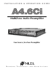
INSTALLATION & OPERATION GUIDE A4.
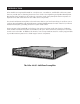
Congratulations! Thank you for purchasing the Niles A4.6Ci MultiZone Preamplifier, one of the most flexible and convenient audio components ever offered. The A4.6Ci, like all Niles products, is built to the highest standards of quality and reliability. With proper installation and operation, you'll enjoy years of trouble-free use. Niles manufactures the industry's most complete line of custom installation components and accessories for audio/video systems.
TABLE OF CONTENTS OPERATIONAL OVERVIEW . . . . . . . . . . . . . . . . . . . . . . . . . . . . . . . . . . . . . . . . . . . . . . . . . . . . . . . . . . . . . . . . . .28 Master Keys/Source Buttons . . . . . . . . . . . . . . . . . . . . . . . . . . . . . . . . . . . . . . . . . . . . . . . . . . . . . . . . . . . . . . . . .28 Master Key/Source Button Events . . . . . . . . . . . . . . . . . . . . . . . . . . . . . . . . . . . . . . . . . . . . . . . . . . . . . . . . . . . . .
TABLE OF CONTENTS Telephone Paging . . . . . . . . . . . . . . . . . . . . . . . . . . . . . . . . . . . . . . . . . . . . . . . . . . . . . . . . . . . . . . . . . . . . . . . .41 System Expansion . . . . . . . . . . . . . . . . . . . . . . . . . . . . . . . . . . . . . . . . . . . . . . . . . . . . . . . . . . . . . . . . . . . . . . . .41 Source-Component Power and Home Theater Synchronization Signals . . . . . . . . . . . . . . . . . . . . . . . . . . . . . . . .41 Keypad Modules . . . . . . . . . . . .
TABLE OF CONTENTS PROGRAMMING STEPS . . . . . . . . . . . . . . . . . . . . . . . . . . . . . . . . . . . . . . . . . . . . . . . . . . . . . . . . . . . . . . . . . . . . .69 Power Commands . . . . . . . . . . . . . . . . . . . . . . . . . . . . . . . . . . . . . . . . . . . . . . . . . . . . . . . . . . . . . . . . . . . . . . .69 Input Assignment . . . . . . . . . . . . . . . . . . . . . . . . . . . . . . . . . . . . . . . . . . . . . . . . . . . . . . . . . . . . . . . . . . . . . . . .
INTRODUCTION Niles Audio has recognized the need for a simple-to-use, cost-effective, and flexible multi-zone system that can provide years of listening pleasure to music-lovers. Our engineering and product-development departments have joined forces to produce an innovative multi-zone preamplifier that incorporates six separate zones and connections for four audio source components. The A4.6Ci MultiZone Preamplifier is the multi-zone solution you have been asking for.
FEATURES AND BENEFITS Multi-zone/Multi-source The A4.6Ci MultiZone Preamplifier incorporates matrix preamplifier technology to provide as many as four source components to six listening zones simultaneously. Finally, Dad can relax to the sound of his favorite music in the den while the kids are listening to their favorite music by the pool. Central Intelligence The design approach of the A4.
FEATURES AND BENEFITS The R-4 Remote - The R-4 Remote provides system control via an ergonomic hand-held IR remote control. Zones that have been installed with Niles IR Sensors can take advantage of the R-4 Remote, providing system control from anywhere in the room. System-Wide Operation The A4.6Ci MultiZone Preamplifier incorporates system-wide control to activate all zones to a particular source component. An ALL OFF command is also included for complete system shutdown from any zone in the system.
PARTS GUIDE (A4.6Ci) LED Zone ON/OFF Indicator Zone Label Slots Removable Programming Cover Figure 2 A4.6Ci Front Panel with Programming Cover Programming Controls and Indicators Connection for Programming Keypads Sensor for Capturing IR Commands DB-9 Computer Interface Zone All On/Page Enable Switches Figure 3 A4.
PARTS GUIDE (A4.6Ci) Audio Inputs with Buffered Cascade Output Four pairs of stereo RCA jacks provide input connections for source components. Each input has a respective buffered cascade output for distributing audio signals for expanded systems. LED Zone ON/OFF Indicators Provides individual ON/OFF indication for each zone. Zone Label Slots Coined slots for placing included room labels, providing zone identification.
PARTS GUIDE SOLD SEPARATELY IntelliPad Ci Keypad Modules Function Keys Master Keys Master Keys Function Keys Zone OFF Key Zone OFF Key Mute Key Mute Key Zone Volume Key Zone Volume Key Solo™ Master Keypad Module Select™ Master Transport™ Master Numeric™ Master Keypad Module Keypad Module Keypad Module Figure 5 Master Keys A quick tap of any of these keys turns on the zone and selects a source component. Pressing and holding these buttons for longer than three seconds turns on all enabled zones.
PARTS GUIDE SOLD SEPARATELY R-4 REMOTE Zone OFF Button Zone Volume Buttons Function Buttons Zone Mute Button Source Buttons Figure 6 Zone Volume Buttons A continuous press of these buttons raises or lowers the volume in your specific zone. Pressing these buttons also restores sound in a muted zone. Source Buttons A quick tap of any of these buttons turns on the zone and selects a source component. Pressing and holding these buttons for longer than three seconds turns on causes all enabled zones.
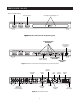
SYSTEM CONFIGURATIONS CONFIGURATION 1 - SIX ZONES Source Components AC Power Cord AUDIO DIGITAL L Niles AC-3 CD CHANGER R Figure 7 Switched AC Outlet DVD DIGITAL AUDIO VIDEO L R DSS DIGITAL AUDIO VIDEO L R PHONE Niles IRC-2P MicroFlashers 12V Trigger Unswitched AC Outlet Video Output Audio Cables Sync Input Audio Inputs Zone Outputs 12V Control Output Niles SI-1260 Zone Inputs Four-Pair Twisted Cable ZONE 4 CK O K CK O U ZONE 5 K AR ED SE N NO CK O U K ED SE AR NO CK O
SYSTEM CONFIGURATIONS Keypads and IR Sensors Keypads and IR sensors enable the user to control the Niles A4.6Ci MultiZone Preamplifier and its connected source components. The source components’ IR commands are programmed into the Niles A4.6Ci MultiZone Preamplifier. These commands are then triggered when the user presses a keypad button or issues a Niles IR command to an IR sensor. Each zone on the A4.
SYSTEM CONFIGURATIONS CONFIGURATION 2 – ADDING ZONES USING MULTIPLE A4.6Ci’s More than one A4.6Ci MultiZone Preamplifier can be used if the system requires more than six zones. A maximum of four A4.6Ci’s (providing up to 24 zones) can be combined to create a larger multi-zone/multi-source system. One A4.6Ci is designated as the Master and the others as Slaves (see Installation Settings on page 65 for more details).
SYSTEM CONFIGURATIONS CONFIGURATION 3 – INTEGRATING AN IR-CONTROLLED HOME THEATER An IR-controlled Home Theater receiver/processor can be integrated to share source components in a system with a Master A4.6Ci. Source Components AUDIO L Home Theater Receiver DIGITAL 1 2 AUDIO VIDEO L R L R R DVD DSS CD CENTER L Video 1 R Video 2 CD CHANGER REAR FRONT L DVD DIGITAL R DIGITAL Niles IRC-2P MicroFlashers AUDIO VIDEO L R 12V D.C.
SYSTEM CONFIGURATIONS CONFIGURATION 4 – INTEGRATING A HOME THEATER USING AN INTELLICONTROL A Home Theater system controlled by a Niles IntelliControl® can be integrated to share source components in a system with the A4.6Ci. Source Components AUDIO Home Theater Receiver DIGITAL 1 2 AUDIO VIDEO L R DVD FRONT L DIGITAL REAR L L R R DVD DSS CD CENTER L Video 1 R Video 2 CD CHANGER R DIGITAL Niles IRC-2P MicroFlashers AUDIO VIDEO L R 12V D.C.
SYSTEM CONFIGURATIONS CONFIGURATION 5 – MULTIPLE MASTER KEYPAD MODULES IN A ZONE The single zone of a Niles A4.6Ci MultiZone Preamplifier can be expanded to contain multiple Solo™ and Select™ Master Keypad Modules, providing control from many locations within the zone. A Niles IntelliPad® Ci Expander™ is required to connect multiple keypads in a single zone. A maximum of five Solo™ Master Keypad Modules can be included in a single zone using two Expanders.
SYSTEM CONFIGURATIONS CONFIGURATION 6 – MULTIPLE LISTENING AREAS IN A ZONE A single zone of the A4.6Ci MultiZone Preamplifier can be set up to contain more than one listening area (i.e., an adjacent living room and dining room). This configuration is chosen when the speakers in the zone are not required to play at separate volume levels or to be on/off separately.
SYSTEM CONFIGURATIONS CONFIGURATION 7 – MORE THAN ONE ROOM IN A ZONE A zone can be divided up into as many as five individual rooms with separate On/Off and Volume controls. A Niles Silencer Volume Control located along with the Master Keypad in each room is required in addition to Niles Expanders.
SYSTEM CONFIGURATIONS CONFIGURATION 8 – SYSTEM PAGING WITH AN EXTERNAL TELEPHONE SYSTEM A Paging Input connection is provided on the rear panel of the A4.6Ci. It provides a connection for the paging output signal of popular telephone systems for voice paging through the speakers located in the listening zones (see Figure 14). System Telephones Telephone Control Unit PAGE OUTPUT Figure 14 A Niles AVDA-3 (see Figure 15) is required when connecting a telephone system to two or more A4.
SYSTEM CONFIGURATIONS CONFIGURATION 9 – IR REPEATING FOR CONTROL OF LOCAL COMPONENTS An IR Repeating System can be integrated into a room connected to the Niles A4.6Ci (see Figure 16). This enables a single IR Sensor (installed in that room) to control local components with a hand-held IR remote control.
COMPONENT COMPATIBILITY INFRARED COMMAND COMPATIBILITY IR control testing was conducted on many equipment brands to determine their compatibility with the A4.6Ci. Typical A/V source components (i.e., CD, DVD, DSS, Cable Boxes, etc.) from each brand were chosen for the test. All brands listed below passed the test.
SOURCE-POWER SYNCHRONIZATION WHAT IS SOURCE-POWER SYNCHRONIZATION? The A4.6Ci has been designed to keep track of the ON/OFF condition of the three source components connected to the system. This allows you to automate source components that utilize the same IR command for ON and OFF. For this feature to function as designed, you need synchronization (sync) between the A4.6Ci and source components that utilize the same IR command for ON and OFF. This assures the users of the system that the A4.
SOURCE-POWER SYNCHRONIZATION CHOOSING A SYNCHRONIZATION METHOD Once you establish that all source components in the system have compatible IR commands, the next step is to choose the appropriate sync method for each component. There are two ways to detect when a component is ON or OFF: Video or Voltage Sync. TV DSS DIGITAL AUDIO VIDEO L R PHONE Video Input RCA Y-Adapter Splitting Video Output Figure 18 Video Sync Video sync is the easiest and most reliable method of synchronization.
SOURCE-POWER SYNCHRONIZATION Voltage Sync Voltage sync is also a reliable method of synchronization if chosen and implemented correctly. The sync inputs can detect the control out voltage from a Niles signal-sensing product interfaced to the source component. Obtaining Voltage Sync Current Sensing Current Sensing synchronizes a component by detecting the changes in the AC power draw that occurs with a component when it turns ON and OFF.
SOURCE-POWER SYNCHRONIZATION Light Sensing Using a light sensor (LS-1) to synchronize your components is usually your last choice, simply because the other choices are more reliable. The Niles LS-1 Light Sensor can synchronize a component by sensing changes in light. The 12V output of the LS-1 is then connected to the A4.6Ci’s sync input dedicated for that component. A miniplug to RCA adapter is required for this connection (see Connections for more information).
OPERATIONAL OVERVIEW MASTER KEYS/SOURCE BUTTONS The Master Keys available on the Solo™ and Select™ Master Keypad Module and the Source Buttons on the hand-held R-4 Remote accessory (Figure 21) provide "one-touch activation" of the A4.6Ci and its connected source components. The Master Keys on the Solo and Select Master Keypad Modules are equipped with back-lit LEDs for indicating Zone ON/OFF, Zone Mute, and Zone Input Selection status.
OPERATIONAL OVERVIEW MASTER KEY/SOURCE BUTTON EVENTS When you press a Master Key on a Solo™ or Select™ Master Keypad Module, or a Source Button on the handheld R-4 Remote accessory, up to six events may occur. Event 1 Event 2 Event 3 Event 4 Event 5 Event 6 Zone-ON Zone-ON Sequence System Input Source Power ON System-ON Sequence Master Key Sequence Event 1 This event turns the appropriate Zone ON when a Master Key is pressed.
OPERATIONAL OVERVIEW MASTER KEY/SOURCE BUTTON OPERATION The Master Key/Source Buttons have two methods for operating the system. Single-Zone Operation The first method, a quick tap of a Master Key/Source Button in a zone (holding the key/button for less than three seconds), causes only that zone to turn ON. The quickly tapped Master Key illuminates GREEN after the zone turns ON.
OPERATIONAL OVERVIEW OFF KEY EVENTS When you press the OFF Key/Button, up to four events may occur. The first event is the Zone OFF sequence programmed by the installer for the zone that is turning OFF. The second event is factory programmed and turns the zone or all zones OFF every time the OFF Key/Button is pressed.
OPERATIONAL OVERVIEW Multiple Rooms in a Zone Using an Expander and Silencers Individual-Room Operation - Multiple rooms within a zone using silencers require two short taps of the OFF Key to turn OFF that zone individually. A press of the OFF Key for less than three seconds in a room that is currently ON (selected Master Key illuminated GREEN) causes that room to MUTE (selected Master Key now illuminates RED).
OPERATIONAL OVERVIEW MUTE KEY/MUTE BUTTON The Mute Key/Button provides a method of turning the sound ON\OFF for a brief moment in an individual zone without turning the zone OFF. (This also prevents the source components from being turned OFF.
OPERATIONAL OVERVIEW FUNCTION KEYS/BUTTONS The Solo™ Master Keypad Module, the Transport™ Accessory Keypad Module and the R-4 Remote include various function keys for control of the connected source components. Figure 23 illustrates the available function keys for all of the control devices.
OPERATIONAL OVERVIEW IDENTICAL SOURCE COMPONENTS The A4.6Ci routes the individual source-component IR commands that with which it has been programmed to specific flasher outputs. This provides individual control of identical source components (i.e., two DSS receivers of the same brand and model). These programmed IR commands are routed to the individual flasher outputs based on the assigned source for which they were programmed.
OPERATIONAL OVERVIEW OPERATING A SYSTEM INTEGRATED WITH A HOME THEATER Operation from the Stereo Zones Provided by the A4.6Ci User operation from the zones provided by A4.6Ci’s, are not affected when integrating a Home Theater to share source components (see System Configurations 3 and 4). Solo™ or Select™ Master Keypad Modules in each zone independently operate the zone to which they are dedicated (i.e., Zone ON/OFF, Volume Up/Down, Mute). When a user in a zone from any A4.
OPERATIONAL OVERVIEW When the Home Theater turns ON, it provides a 12V status signal that is connected to the Home Theater sync input on the rear panel of the A4.6Ci. This 12V status signal provides the ON/OFF status of the Home Theater to the A4.6Ci. The moment a valid Home Theater sync signal is present at the A4.6Ci, the A4.6Ci’s 12V control output sends a turn-on trigger for a voltage-triggered AC power strip (i.e., Niles AC-3), activating latching source components.
OPERATIONAL OVERVIEW PLACEMENT Place the A4.6Ci on a flat, level surface such as a table or shelf, with its weight equally distributed on each of its four feet. Like any high-fidelity component, the A4.6Ci will last much longer if it receives adequate ventilation for proper cooling (see Figure 28). Figure 28 Make sure that there is a minimum of 1” of free air space above the preamplifier and 1” on each side for proper ventilation.
CONNECTIONS TERMINATING FOUR-PAIR TWISTED CABLE The Solo™ and Select™ Master Keypad Modules, the expander, and the A4.6Ci’s system-expansion connections require a four-pair twisted cable with a one-to-one wiring configuration. To maintain consistency throughout all Intellipad ® Ci installations, we recommend the color-coding pattern described in Figure 31. However, you may follow the color-coding pattern of your choice, as long as it is consistent throughout the system.
CONNECTIONS CONNECTING IR SENSORS An IR sensor can be connected to a Solo™ and Select™ Master Keypad Module in one of two ways, directly with a four-pair twisted cable (see Figure 34 and 35), or with a three-wire to RJ-45 adapter available from Niles for IR sensors installed with two-conductor shielded cable. (See Figure 36 and the Accessories Section of this manual.
CONNECTIONS 1 2 3 9 4 10 5 11 12 6 7 13 14 8 15 Figure 37 SOURCE-COMPONENT AUDIO SIGNALS SOURCE-COMPONENT POWER AND HOME THEATER SYNCHRONIZATION SIGNALS 1 Audio Output of Source Components to the A4.6Ci 1. Male-to-male RCA audio cables connect the four external audio sources. 5 12V Home Theater Sync to Home Theater Sync Input 5. The 12V Home Theater sync signal connects with a mini-plug to the Home Theater sync input. 2 Buffered-Cascade Audio Output of Source 2. Components to Slave A4.
CONNECTIONS HOME THEATER CONTROL SYSTEM 12V CONTROL SIGNALS 7 Voltage Sync from a Source Component to an 7. A4.6Ci Sync Input When obtaining a 12V sync signal from a source component (refer to the Source Power Synchronization section of this manual for more information), a Niles Accessory Cable (FG00724) connected to a Radio Shack 274-326 mini-plug to male RCA adapter provides proper connection to any of the three source sync Inputs. 12 1. IR FLASHERS 13 1.
CONNECTIONS CONNECTING AN IR SENSOR FOR LOCAL SYSTEM CONTROL IR Sensors installed in zones for hand-held IR remote control of the A4.6Ci and its connected source components can also be used to control local components (i.e., a TV, DSS, DVD, and a surround-sound system located in the master bedroom zone as shown in Figure 38). The IR sensor connects normally to the Solo™ and Select™ Master Keypad to control the A4.6Ci and its connected source components.
CONNECTIONS CONNECTING AN A/B AMPLIFIER SWITCH FOR LOCAL SYSTEM SELECTION A Niles SPK-1 Voltage-Activated Speaker Level A/B Switcher connects to both the A4.6Ci and a local system to provide sound from each system to the same speakers located in a single zone. The local system only connects to the speakers when the local system is turned on. The Niles A4.6Ci connects to the speakers by default when the local system is off. As shown in Figure 39, the zoned speaker output of the A4.
PROGRAMMING OVERVIEW PROGRAMMING PANEL IR commands needed for control of connected external source components are programmed into the A4.6Ci’s program memory using the hidden programming controls on the front panel (see Figure 42). Programming is accomplished by using the hidden panel’s push buttons and LED prompts, and by sending commands from connected Niles Master Keypad and Accessory Keypad Modules, and IR commands from the remotes supplied with the source components (see Figure 41).
PROGRAMMING OVERVIEW INSTALLATION AND PROGRAMMING DOCUMENTATION Why Document? There are three important reasons why you should keep thorough documentation of the installation and the programming procedure: • It enables you to program the system properly. When using multiple preamplifiers or programming sequences, knowing where individual IR commands are programmed is critical. Precise documentation minimizes delays due to poor planning, and avoids duplication of effort.
PROGRAMMING OVERVIEW INTELLIPAD Ci EXPANDER INSTALLATION SCHEMATIC MULTI-AREA ZONE 1 2 JOB TITLE INTELLIPAD Ci EXPANDER INSTALLATION SCHEMATIC MULTI-ROOM ZONE 1 SYSTEM DESIGNER 3 OUTPUT CONNECTION TO A4.6Ci OUTPUT CONNECTION TO A4.
PROGRAMMING OVERVIEW PROGRAMMING WORKSHEET #3 FUNCTION KEY IR ❏ SLAVE 1 ❏ SLAVE 2 1 2 JOB TITLE SYSTEM DESIGNER ❏ SLAVE 3 KEYS ▼ ▼ PAGES ▼ FUNCTION KEYS 1 2 3 4 6 5 7 8 Default PAGES KEYS ▼ Library 1 1 2 2 3 3 4 4 5 5 6 6 7 7 8 8 9 9 0 0 - - + + RANDOM RANDOM GROUP GROUP DISC DISC FAV FAV PLAY PLAY STOP STOP PAUSE PAUSE REW REW FF FF M M G G E E P P UP UP DOWN DOWN LEFT LEFT RIGHT RIGHT * * AM AM FM FM SURF + SURF + SURF
PROGRAMMING OVERVIEW SYSTEM-INSTALLATION SCHEMATICS The first information to document is the makeup of your system. Establish how many zones are involved, and the number of preamplifiers in your system. Next, determine how many zones have more than one room, requiring the use of an expander. From this information, you will know which sheets to fill out and how many of each you will need. Use a pencil when completing the sheets. If you need additional sheets, make photocopies.
PROGRAMMING OVERVIEW 9 MASTER A4.6Ci ALL ON / PAGE ZONE ❏ ❏ ❏ ❏ ❏ ❏ 1 2 3 4 5 6 10 DIP switches on the front panel determine which zones will be enabled to the ALL-ON and PAGE features. CASCADE OUTPUT SOURCE ❏ YES ❏ NO SOURCE DESTINATION 1 2 3 4 Check those that have been enabled to the ALL-ON/PAGE feature.
PROGRAMMING OVERVIEW Expander Installation Schematic If your system has zones that require more than one keypad, install expanders in those zones. The Expander Schematic sheet (Figure 44) enables you to document each of those additional keypads. Multi-Area Zone 1 2 JOB TITLE SYSTEM DESIGNER Mr. Smith John Doe Document the customer’s name. Document the system designer’s name. 3 OUTPUT CONNECTION TO A4.6Ci ZONE# Master 6 The A4.6Ci to which the expander is connected (Master or Slaves 1, 2, or 3).
PROGRAMMING OVERVIEW Multi-Room Zone In a multi-room zone, the information to document in the Expander Schematic Multi-Room sheet (Figure 44) is the same as in a Multi-Area Zone. The only difference is that you need silencers in all rooms for individual volume control. 1 2 JOB TITLE SYSTEM DESIGNER Mr. Smith John Doe Document the customer’s name. Document the system designer’s name. 3 OUTPUT CONNECTION TO A4.6Ci ZONE# Master 6 The A4.
PROGRAMMING OVERVIEW Slave Preamplifier Installation Schematic After filling out the Master Preamp Schematic and any necessary Expander Schematics for the Master, you are ready for the Slave Preamp Schematic sheet (Figure 43) if the system has more than six zones. Fill out one sheet per Slave A4.6Ci. 1 2 JOB TITLE SYSTEM DESIGNER Mr. Smith John Doe Document the customer’s name. Document the system designer’s name.
PROGRAMMING OVERVIEW 9 8 CASCADE OUTPUT SOURCE ❏ YES SOURCE ZONE OUTPUT SOURCE ❏ RCA ❏ NO ZONE DESTINATION 1 1 2 2 3 4 3 4 5 6 This documents the audio output from the shared source components going to the next Slave or the Home Theater. • Does your system include other preamps or a Home Theater? (YES/NO) • If yes, specify where the cascade output is going (for example, a Home Theater or the next Slave preamp in the system).
PROGRAMMING OVERVIEW SYSTEM PROGRAMMING WORKSHEETS After documenting what is being installed (every keypad, every expander, every zone, every preamp), you can now document all IR programming used in the system. Following are detailed descriptions of the six Programming Worksheets. Worksheet #1, Source Power IR and Master Key Setup Worksheet #1 documents which source components need to have their power command programmed into the preamp.
PROGRAMMING OVERVIEW Worksheets #2 and #3, Function-Keys Programming Worksheets Worksheets #2 and #3 document the IR commands stored in each of the available function keys for all 10 Pages (i.e., eight Master Key Pages, the Library page, and the Default Page). Note that the worksheet lists all available Master Keys for the Solo™ and Select™ modules, and all available function keys for the Numeric™ and Transport™ accessory modules. You will need a worksheet for each A4.6Ci in your system.
PROGRAMMING OVERVIEW Worksheet #3, Slave A4.6Ci Function-Keys Planning Worksheet Worksheet #3 (Figure 47) documents IR commands programmed into the Slave A4.6Ci’s. Because any IR command programmed into a Slave is transparent to the system during normal operation, these commands cannot be used to operate the sources. The IR commands documented in Worksheet #3 are to be used in the zone On/Off sequences for their respective Slave A4.6Ci. 1 2 JOB TITLE SYSTEM DESIGNER Mr.
PROGRAMMING OVERVIEW Worksheet #4, Master-Key Sequence Programming Worksheet #4 documents the Master Key Sequences that will be performed whenever a Master Key is pressed. Indicate each step of the sequences, identifying where the IR commands were programmed by using their page and key address. The only Master Key Ending Sequences that can be built are for the Master A4.6, and you may have as many as eight. Copy the worksheet as needed. 1 2 JOB TITLE SYSTEM DESIGNER Mr.
PROGRAMMING OVERVIEW Worksheet #5, Zone On/Off and System On/Off Sequence Programming Worksheet #5 documents the steps of the sequences that occur whenever a zone first turns on and when the zone turns off. Identify where the IR commands were programmed by using their page and key address. Copy the worksheet as needed to document zone sequences for the Master A4.6Ci and all the Slaves in your system. It also documents the steps of the sequences that occur whenever the system turns on and when it turns off.
PROGRAMMING OVERVIEW Worksheet #6, Function-Key Sequence Programming Worksheet #6 documents the steps of the sequences that have been programmed into any of the available Function Keys for the Master A4.6Ci only. Identify where the IR commands were programmed by using their page and key address. Copy the worksheet as needed to document all Function Key sequences.
PROGRAMMING OVERVIEW PROGRAMMING A LEARNING REMOTE FOR ZONE OPERATION USING KEYPAD MODULES Learning remote controls can be taught the IR commands to provide individual zone operation. These IR commands operate the A4.6Ci and its associated source components from any zone equipped with an IR sensor. Important Note: IR sensors cannot operate a zone when used alone. They must be installed and connected to a Solo™ or Select™ Master Keypad Module.
PROGRAMMING OVERVIEW PROGRAMMING A LEARNING REMOTE FOR ZONE OPERATION USING THE NILES R-4 REMOTE Learning remote controls can be taught the IR commands of the hand-held Niles R-4 Remote to provide individual zone operation. These IR commands operate the A4.6Ci and its associated source components from any zone equipped with an IR sensor. Important Note: IR sensors cannot operate a zone when used alone. They must be installed and connected to a Solo™ or Select™ Master Keypad Module.
PROGRAMMING OVERVIEW Method #1– Controlling Shared Source Components with IR Repeating and 12V Home Theater Status Method #2 – Controlling Shared Source Components with Niles R-4 Commands and 12V Home Theater Status When using IR repeating, IR programming for the source components can be accomplished by programming the actual IR commands from the source component’s included remote control into the Home Theater learning remote control.
PROGRAMMING OVERVIEW To operate the shared source components, follow the criteria specified in Method 1 and Method 2, to select the most appropriate method of operation for your system. You can program the Home Theater's learning remote with the components' IR commands, or with Niles function buttons commands when using this method. Important Note: There is no need to teach the Niles OFF command to the Home Theater learning remote control when using Method #2.
INSTALLATION SETTINGS SETTING ALL ON/PAGE MODE There are six All ON/PAGE switches located on the hidden programming panel of the A4.6Ci. Each of the A4.6Ci's zones has a corresponding numbered switch (see Figure 40). The switches enable (up) or disable (down) the individual zones from responding to ALL ON commands and incoming audio pages. Figure 40 SETTING MASTER/SLAVE MODE The factory default mode of the A4.
INSTALLATION SETTINGS ALL ON Volume Level When a system-wide ON command is issued, zones that are turned OFF turn ON to the ALL ON volume level set by the factory in the A4.6Ci. (Volume levels in zones that are already turned ON do not change during a system wide ON command.) The factory level for ALL ON is a relatively low volume level. It can be adjusted individually for each zone using the acoustic setting mode detailed in this section of the manual.
INSTALLATION SETTINGS Step 3. Press the ON button to turn the zone ON. The Power LED indicates the current preamplifier output mode (GREEN for Variable and RED for Fixed). To Turn a Zone ON/OFF Step 1. Press and hold the ZONE SELECT button. Zone #1 LED blinks GREEN. Step 2. If Zone 1 is not the zone you wish to activate, continue to tap ZONE SELECT until the LED for the desired zone starts blinking. Step 4.
INSTALLATION SETTINGS All ON/Fixed Volume Step 6. Master Key #1 lights up, indicating you are ready to adjust ALL ON Volume if the zone is set to variable mode. If the zone is set to fixed mode, you are adjusting the volume level to which the zone will always be set. Step 15. Tap the same key again (depending on your keypad module) to turn loudness OFF. Flat Tap any other key (besides the five Master Keys and the Arrow Up key) for acoustic adjustments to revert to flat.
PROGRAMMING STEPS Important Note: Before you start programming the A4.6Ci: • Assign components with a single, toggle command for ON and OFF to Inputs 1 and 2. These inputs have sync. • Assign components with separate ON and OFF commands to Inputs 3 and 4. These inputs do not have sync. Set-Up 1. Remove the programming cover to reveal the programming panel. 2. Connect a Master Keypad into the keypad input to the far right of the panel.
PROGRAMMING STEPS The PAGE LED turns off, and the ENTER IR LED turns on GREEN. The ENTER IR LED turns on RED to indicate it is ready to receive the OFF command. Step 3 - Press the appropriate power or ON button on the original factory remote. Step 4 - Press the OFF button on the original factory remote if the component has discrete ON and OFF commands. The ENTER IR LED turns OFF, and the PAGE LED blinks RED. Or press the PROGRAM button if the component has one power command for both ON and OFF.
PROGRAMMING STEPS Step 5 - To test the captured IR command(s), install a flasher for the source component. Tap the TEST button. The ENTER IR LED may flicker, blink, or be intermittently solid GREEN to reflect real-time IR. Step 6 - If the command turns on the source, tap the TEST button again to turn it off and continue your manual programming. or If the command fails to operate the source component, press the same Master Key again to erase the IR command automatically.
PROGRAMMING STEPS INPUT ASSIGNMENT Step 1 - Press a Master Key to assign one of the four audio inputs corresponding to the source component that Master Key will activate. It doesn’t matter how the input assignment is ordered. For example, I can have input 3 assigned to Master Key 1, input 4 assigned to Master Key 2, and so on. Select™ Transport™ Numeric™ The PAGE LED turns off and one of the INPUT LEDs turns on RED.
PROGRAMMING STEPS Step 5 - When all the necessary inputs have been assigned, press the NEXT button to continue programming. The FUNCTION-KEY IR/(FUNT. KEY SEQ.) LED turns on RED, and the PAGE LED blinks RED. FUNCTION-KEY IR Step 1 - Press the appropriate Master Key to choose the page for programming the individual IR commands stored to the various Function Keys. Each Function Key can store one IR command per available Master Key Page. To program function keys within the Default Page, tap the OFF Key.
PROGRAMMING STEPS Step 3 - Press the appropriate command on the original factory remote. The ENTER IR LED turns OFF, and the KEY LED blinks RED. Step 4 - To test the captured IR command, install a flasher for the source component and press the TEST IR button. The ENTER IR LED may flicker, blink, or be intermittently solid RED to reflect real-time IR activity during IR transmission and then turn OFF again.
PROGRAMMING STEPS Step 7 - Press the PROGRAM button to select a different Master Key Page. The KEY LED turns OFF, and the PAGE LED blinks RED. Step 8 - Repeat steps 1 through 7 until all the necessary IR commands have been stored, and all Function Keys have been programmed for all the Master Key Pages. When all the necessary Function-Key IR commands have been programmed, press NEXT to continue programming. The POWER/MASTER KEY SEQ.
PROGRAMMING STEPS Step 2 - Press the Master Key that identifies the Master Key Page where the IR command is stored for the first step in the Master Key Sequence you are programming. or Tap the OFF Key if the IR command is in the Default Page. or Press and hold the OFF key if the IR command is in the Library Page. Select™ Transport™ Numeric™ The PAGE LED turns OFF, and the KEY LED blinks RED. Step 3 - Press the Function Key where the IR command is stored.
PROGRAMMING STEPS Step 4 - To insert delays, press the DELAY button instead of a Function Key, while the PAGE LED is blinking RED. The PAGE LED turns OFF, the KEY LED blinks RED, and the first four keys on the Master Key module illuminate. Step 5 - Choose the Master Key for the desired delay time. Refer to the table below: DELAY TABLE KEY Master Master Master Master Key Key Key Key 1 2 3 4 DELAY TIME .
PROGRAMMING STEPS Step 7 - Repeat steps 2 through 6 to continue identifying the Master Key Pages where the IR commands are stored for all the steps in the Master Key Sequence you are programming. Step 8 - Press the PROGRAM key to program the Master Key Sequence for a different Master Key. The TRIGGER LED turns on RED, and the PAGE LED continues to blink RED. Step 9 - Repeat steps 1 through 8 until all Master Key Sequences have been programmed.
PROGRAMMING STEPS ZONE ON/OFF AND SYSTEM ON/OFF SEQUENCE Step 1 - Press ZONE SELECT until the LED for the desired Zone blinks GREEN. All other LEDs turn off. When you pass Zone 6, all LEDs blink. (Press it once more and you go back to Zone 1 to program the Zone On/Off Sequence.) Step 2 - Press the ZONE ON button to program the Zone ON Sequence for the desired zone or to program the System ON Sequence if you have selected all zones.
PROGRAMMING STEPS Step 3 - Press the Master Key that identifies the Master Key page where the IR command is stored for the first step in the Zone On/Off or System On/Off sequence you are programming. or Tap the OFF Key if the IR command is stored in a Function Key within the Default Page. Master Keys 1 and 3 illuminate. or Press and hold the OFF Key if the IR command is stored in a Function Key within the Library Page. Master Keys 1, 3, and 4 illuminate, simulating an “L.
PROGRAMMING STEPS Step 5 - Select the page where the next IR command is stored to continue the Zone On/Off or System On/Off sequence you are programming. (You can press a Master Key, tap the Off Key for the Default page, or press and hold the Off Key for the Library page). Select™ Transport™ Numeric™ The PAGE LED turns OFF, and the KEY LED blinks RED. Step 6 - To insert delays, press the DELAY button instead of a Master Key, while the PAGE LED is blinking RED.
PROGRAMMING STEPS After you choose a delay, all Master Keys turn off. The KEY LED turns OFF, and the PAGE LED blinks RED. Step 8 - To add another delay, press the DELAY button again, and repeat the previous step. (For example, you can have two consecutive one-second delays.
PROGRAMMING STEPS Step 11 - Repeat steps 2 through 10 until all Zone On/Off or System On/Off sequences have been programmed. Note: If you missed IR commands in a sequence, re-do the programming for the whole sequence. Whatever was previously programmed is automatically replaced. Step 12 - Press NEXT to continue programming. The FUNCTION KEY IR/FUNCT. KEY SEQ. LED is on GREEN, the TRIGGER LED is on RED, and the PAGE LED is blinking RED.
PROGRAMMING STEPS Step 2 - Press the actual Function Key that triggers the sequence. Select™ Transport™ Numeric™ The TRIGGER LED turns OFF, the PAGE LED blinks RED, and the KEY LED turns OFF. Step 3 - Press the Master Key that identifies the Master Key Page (or tap the OFF Key for the Default Page, or press and hold the OFF Key for the Library Page) where the IR command is stored for the first step in the Function-Key Sequence.
PROGRAMMING STEPS Step 4 - Press the Function Key where the IR command is stored. Select™ Transport™ Numeric™ The KEY LED turns off, and the PAGE LED blinks RED. Step 5 - To insert delays, press the DELAY button instead of a Master Key while the PAGE LED is blinking RED. The PAGE LED turns off, the KEY LED blinks RED and the first four keys on the Master-Key Module illuminate.
PROGRAMMING STEPS Step 6 - Choose the Master Key for the desired delay time. Refer to the table below: DELAY TABLE KEY Master Master Master Master Key Key Key Key 1 2 3 4 DELAY TIME .5 seconds 1 seconds 4 seconds 8 seconds For example, if you press Master Key 2, a one-second delay is added to the sequence. After you choose a delay, all Master Keys turn off. The KEY LED turns OFF, and the PAGE LED blinks RED. Step 7 - To add another delay, press the DELAY button again, and repeat the previous step.
PROGRAMMING STEPS Step 10 - Repeat steps 2 through 9 until you have programmed all the Function-Key Sequences within the selected Master Key Page. Step 11 - Press the PROGRAM button twice to program sequences within other Master Key Pages. The TRIGGER LED turns on RED, the PAGE LED blinks RED. Step 12 - Repeat steps 1 through 11 until you have programmed all the Function-Key Sequences for all Master Key Pages. Step 13 - Press the PROGRAM button three times to save and exit the Programming Mode.
PROGRAM-EDITING STEPS EDIT SOURCE-COMPONENT POWER Steps to edit the IR commands to power IR activated source components. Step 1 - Press and hold the PROGRAM button. The POWER/(MASTER KEY SEQ) LED turns on RED, and the PAGE LED blinks, RED. Step 2 - Press a Master Key where you will edit source component power IR commands. Important Note: Every Master Key that activates a source component with IR must be programmed individually. The PAGE LED turns off, and the ENTER IR LED turns on GREEN.
PROGRAM-EDITING STEPS Step 5 - Repeat steps 3 and 4 until all inputs have been edited. Step 6 - Press NEXT to edit Function Key IR. The FUNCTION KEY IR/(FUNCT. KEY SEQ.) LED turns on RED, and the PAGE LED blinks RED. or Step 7 - Press PROGRAM again to save and exit programming. EDIT FUNCTION KEY IR PROGRAMMING Steps to edit the individual IR commands stored to the various Function Keys. Step 1 - Press and hold the PROGRAM button. Step 2 - Press the NEXT button twice. The FUNCTION KEY IR/(FUNCT. KEY SEQ.
PROGRAM-EDITING STEPS EDIT MASTER KEY SEQUENCE PROGRAMMING Step 1 - Press and hold the PROGRAM button. Step 2 - Press the NEXT button three times. The (POWER)/MASTER KEY SEQ LED turns on GREEN, the TRIGGER LED turns on RED, and the PAGE LED blinks RED Step 3 - Press the Master Key to edit. The TRIGGER LED turns off, and the PAGE LED continues to blink RED.
PROGRAM-EDITING STEPS iii. Press the DELAY button again and repeat the previous step to add another delay. (For example, you can have two consecutive one-second delays.) or Continue with your editing. Step 7 - Repeat steps 4 – 6 until you have re-entered all the steps for the Master Key Sequence you are editing. Step 8 - Press the PROGRAM key to edit the Master Key Sequence for a different Master Key. The TRIGGER LED turns on RED, and the PAGE LED continues to blink RED.
PROGRAM-EDITING STEPS Press the OFF Key if the IR command is stored in a Function Key within the Default Page. Master Keys 1 and 3 illuminate, indicating you are selected to the Default Page. or Press and hold the OFF Key if the IR command is stored in a Function Key within the Library Page. Master Keys 1, 3, and 4 illuminate, simulating an "L." This indicates that you are selected to the Library Page. The PAGE LED turns off and the KEY LED blinks RED.
PROGRAM-EDITING STEPS Step 9 - Repeat steps 3 through 8 until all Zone/System Sequences have been edited. Note: If you missed IR commands in a sequence, re-do the whole sequence. Step 10 - Press Next to edit Function-Key Sequences. The (FUNCTION KEY IR)/FUNCT. KEY SEQ LED turns on GREEN, the TRIGGER LED turns on RED, and the PAGE LED blinks RED. or Step 11 - Press PROGRAM again to save and exit programming.
PROGRAM-EDITING STEPS ii. Choose the Master Key for the desired delay time. Refer to the table below: DELAY TABLE KEY Master Master Master Master Key Key Key Key 1 2 3 4 DELAY TIME .5 seconds 1 seconds 4 seconds 8 seconds For example, if you press Master Key 2, a one-second delay is added to the sequence. After you choose a delay, all Master Keys turn off. The KEY LED turns OFF, and the PAGE LED blinks RED. iii. Press the DELAY button again and repeat the previous step to add another delay.
PROGRAM-EDITING STEPS STEPS TO ERASE SOURCE-COMPONENT POWER To erase source-component power commands, follow the same steps as if you were going to store the power command up to when you would press the remote to enter the command. Press PROGRAM to exit. The power command is erased automatically. Step 1 - Press and hold the PROGRAM key to enter Program Mode. The POWER/(MASTER KEY SEQ) LED turns on RED, and the PAGE LED blinks RED. Step 2 - Press the Master Key where you wish to erase source IR commands.
PROGRAM-EDITING STEPS STEPS TO ERASE MASTER-KEY SEQUENCES To erase Master-Key Sequences, follow the same steps as if you were going to build the sequences, up to when you identify the page and key address where the individual commands are stored. Instead, press the PROGRAM key to erase the sequence and exit. Step 1 - Press the PROGRAM button once, then the NEXT button three times. The (POWER)/MASTER KEY SEQ LED turns on GREEN. Step 2 - Press a Master Key or press the OFF Key.
PROGRAM-EDITING STEPS STEPS TO ERASE FUNCTION-KEY SEQUENCES To erase sequences, follow the same steps as if you were going to store the commands, up to when you identify the page and key address where the individual commands are stored. Instead, press the PROGRAM key to erase the sequence and exit. Step 1 - Press the PROGRAM button once, then the NEXT button five times. The (FUNCTION KEY IR)/SEQ LED turns on GREEN, the TRIGGER LED turns on RED, and the PAGE LED blinks RED.
A4.6Ci SYSTEM ACCESSORIES IntelliPad® Ci Keypads and Remote Control Solo™ Master Keypad Module Select™ Master Keypad Module STOCK # STOCK # FG00807 FG00808 • Backlit Master Keys enable monitoring and control of up to four audio sources or other remote controllable devices (see Niles MultiZone Control System for details). All keypad buttons are programmable and capable of automating multiple commands with the single touch of a button.
A4.6Ci SYSTEM ACCESSORIES IR Sensors and IR Flashers IntelliPad® Ci Adapter Cable TIR1+ IR Sensor STOCK # STOCK # FG00852 FG00649 • Allows for easy connection of Niles IR Sensors (that have been installed with two-conductor shielded cable) to IntelliPad® Ci Master Keypad Modules. • Utilizes a three-position set-screw connector on one end for connection of a two-conductor shielded cable.
A4.6Ci SYSTEM ACCESSORIES Sync Accessories Many of the components in your system should have their power status “synced” to the A4.6Ci. The following accessories either sense that a component is on/off or actually turn the component(s) on/off.
A4.6Ci SYSTEM ACCESSORIES Convenience Outlets NET-2S Computer Network Convenience Outlets NET-2D Computer Network Convenience Outlets ColorStock# Almond Bone White ColorStock# Almond Bone White FG00858 FG00840 FG00842 FG00859 FG00843 FG00844 Two 8-Wire (RJ-45) modular jacks for computer network or IntelliPad Ci Master Keypad connections. Standard-style faceplate. Two 8-wire (RJ-45) modular jacks for computer network or IntelliPad™ Ci Master Keypad connections. Decora®-style faceplate.
TROUBLESHOOTING TROUBLESHOOTING THE A4.6CI Problem Troubleshooting The A4.4Ci has no lights on. Inspect the DC power adapter. Be sure it is inserted firmly into the powercord socket of the A4.6Ci. Check the AC power outlet. Verify that the outlet is providing power (i.e., a switched AC outlet).You want to make sure that the A4.6Ci is always plugged into an un-switched AC outlet. If you've checked the cord and the outlet and you still have no lights, call Niles for service.
SPECIFICATIONS A4.6Ci MultiZone Audio Preamplifier Frequency Response: 12 Hz - 230 KHz, 3 dB, at 1Vrms output Paging = -3dB > 200Hz - 4 KHz Distortion: <0.
NOTES 104
NOTES 105
Niles Audio Corporation 12331 S.W. 130 Street, Miami, FL 33186 Mailing Address: P.O. Box 160818 Miami, FL 33116 Customer Service: 1-800-BUY-HIFI (1-800-289-4434) Phone: 305-238-4373 • Fax: 305-238-0185 Visit us on the web at www.nilesaudio.com ©2002 Niles Audio Corporation. All Rights reserved. Niles and the Niles logo are registered trademarks of Niles Audio Corporation.
SPECIFICATIONS A4.6Ci MultiZone Audio Preamplifier Frequency Response: 12Hz - 150kHz, -3dB, at 1Vrms output Distortion: <0.