I N S TA L L AT I O N G U I D E H O M E T H E AT E R A U T O M AT I O N A N D C O N T R O L S Y S T E M ��� �������������������������������
CONGRATULATIONS! Thank you for purchasing the iC2 Home Theater Automation and Control System from Niles. With proper installation and operation, you should enjoy years of trouble-free use. Niles manufactures the industry’s most complete line of custom installation components and accessories for audio/video systems. To see the complete Niles product assortment, visit us on the Internet at: www.nilesaudio.
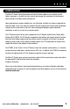
INTRODUCTION The Niles iC2 Home Theater Automation and Control System addresses an essential need of today’s consumers—the ability to easily control and manage the assortment of entertainment sources found in the home theater environment. Home entertainment systems should be fun, not frustrating, and Niles has always recognized the need for simple-to-use, cost-effective solutions.
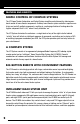
FEATURES AND BENEFITS SIMPLE CONTROL OF COMPLEX SYSTEMS The iC2 Home Theater Automation and Control System simplifies entertainment by allowing onetouch control of home theater components. Ordinary home theater system controllers require users to turn on (and off) multiple components, resulting in a confusing situation of hunting down the fugitive component that is “off,” when it really should be “on.
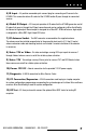
INSTALLATION FLEXIBILITY With a low profile design, easy-to-access connections, and mounting wings with rack-mount spacing, the HT-MSU can be wall-mounted behind theater components or attached to the back of metal professional racks. The HT-MSU incorporates an infrared pass-through port allowing control over sources that use original remotes, even if the system is hidden from view. RELIABLE ZIGBEE® RF COMMUNICATION The iC2 System uses a very reliable 2.
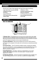
CONTENTS Check that your iC2 Home Theater Automation and Control System contains the following: • Home Theater Main System Unit (HT-MSU) • HT-MSU Power Supply • RF Antenna • Antenna Wall Bracket • 10' (3 meters) Antenna Extension Cable • End User Guide • iC2 Remote + Battery • iC2 Remote Charging Power Supply • Master Key Label Sheet • 10 iC2 Remote Master Key Caps • System Configuration Worksheet • Ferrite Bead PARTS GUIDE THE IC2 REMOTE 5 4 3 1 � � � ���� ������ � � � � � � � � � ���
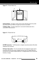
Figure 2. iC2 Remote Bottom View 6 7 6) Reset Button - This button is used to reset the remote. Should the remote lock up and/or not communicate with the HT-MSU, use a paper clip to access the reset button. 7) Battery Door - The battery compartment is accessed via the battery door, which is secured with a Phillips head screw. Figure 3. iC2 Remote Rear View 8 9 8) USB Connection - The USB connection is a diagnostic connection used by the Niles Audio Corporation Service Center only.
THE HOME THEATER MAIN SYSTEM UNIT (HT-MSU) 7 1 10 9 8 2 3 13 4 5 6 11 12 Figure 4. HT-MSU Top View 1) IR Outputs - SRC1 – SRC6, TV/7, RCV/8 are eight dedicated 3.5mm jack source flasher outputs that output IR data specifically for that source. 2) RS232 Outputs - SRC1 – SRC6, TV/7 and RCV/8 are eight dedicated 3.5mm jack source serial outputs that output RS232 data specifically for that source. 3) Assignable 12V Outputs - Three 3.5mm jacks, output 12V DC 150mA when activated: a.
5) IR Input - A 4-position removable quick connect plug for connecting an IR sensor to the HT-MSU. This connection allows IR control of the HT-MSU and/or IR pass-through for connected sources. 6) Global IR Output - A 3.5mm jack provides all IR codes that the HT-MSU generates and all IR codes that come in through the IR Input connection and can be configured via Niles QuickConfig for Normal or High output.
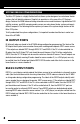
SYSTEM DESIGN CONSIDERATIONS The Niles iC2 System is a highly flexible tool that allows system designers to create home theater systems that will delight customers. Simplicity in operation is at the core of the iC2 System’s design. Features like HDMI video switching surround receivers and televisions, high-definition DSS satellite receivers, and DVD managing media servers can make home theater systems extremely difficult to operate.
SOURCE POWER STATUS CONNECTIONS To properly automate home theater sources, the HT-MSU needs to “know” when the source is powered On or Off. There are three ways that sources are powered on: 1. Toggle Power: A source via its remote control has one button for turning that source On and Off. When trying to automate such a device, you must provide the HT-MSU the “Power Status” as feedback using the Status connection on the HT-MSU’s top edge (detailed below). 2.
ASSIGNABLE 12 VOLT OUTPUTS These three ports are completely assignable and can be used to trigger out-board automation devices such as: • 12V Triggered AC Power strips like the Niles AC-3 • 12V Triggered subwoofers like the Niles SW300, SW12, SW10, and Pro15SW • 12V Triggered Dipole/Bipole rear effects speakers like the StageFront IW650FX • Motorized drapery systems and projection screens 12V Output #1 has a default setting to output 12V DC whenever the home theater receiver is turned on by the HT-MSU Maste
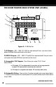
SYSTEM CONFIGURATION 1 SINGLE TV WITH A COMBINATION OF IR AND RS232 CONTROLLABLE SOURCES Flat Panel Display HT Receiver Satellite Receiver Media Server CS12V 12 V DC Power Supply DVD Player Portable Docking Station HT-MSU Motorized Lift CD Disc Changer WS110 Flasher 12 Volt RS232 2 Conductor Video Synch RF ZigBee Antenna AC-3 Remote iC2 Remote Figure 5. System Configuration 1 In System Configuration #1 (Figure 5), the flat panel TV is controlled via the RS232 connection TV/7 on the HT-MSU.
SYSTEM CONFIGURATION 2 DUAL TV MODE AND INTEGRATION WITH AN IR CONTROLLED MULTIZONE RECEIVER HT Receiver Flat Panel Display Portable Docking Station 12 V DC Power Supply Projector RS232 Controllable Listing System Motorized Projection Screen RF ZigBee Antenna HT-MSU Multizone Receiver with IR Interface CS12V iC2 Remote See Figure 7 DVD Player Flasher 12 Volt RS232 Video Synch TiVo® Figure 6.
System Configuration #2 also shows an RS232 controllable lighting system connected to the HT-MSU RS232 SRC6 port. In this configuration, there are 2 sources (a DVD and a DSS satellite receiver) being “shared” with the house-wide multizone distributed audio receiver. The HT-MSU sends IR codes for both of the shared sources out of the Global IR Output port into the multizone’s IR IN port.
The final design feature in System Configuration #3 uses a Niles Radio Frequency Gateway (RFG) to extend the antenna away from the HT-MSU. The Niles iC2 HT-MSU comes with an RF antenna that can be connected directly to the HT-MSU antenna socket. Reception range is approximately 75 feet (22.86 meters). We recommend using the 10 foot antenna extension cable to position the RF antenna away from the home theater sources.
The HT-MSU is supplied with a 10 foot antenna extension cable to allow the antenna to be placed away from the HT-MSU. An antenna wall-bracket is also supplied so the antenna can be attached high on the wall behind the equipment. NOTE: HOME THEATER EQUIPMENT, DIGITAL SOURCES AND RACKS ARE MADE OUT OF METAL AND CAN CAUSE INTERFERENCE OR “SHADOWS” IN RF RECEPTION. NILES HIGHLY RECOMMENDS YOU PLACE THE ANTENNA AS HIGH AS POSSIBLE AND AWAY FROM THE MAIN SOURCE GEAR AND EQUIPMENT RACK.
5) 12V Output and Relay Wiring: The HT-MSU has three 12V and three “Dry Contact Closure” Relay Outputs that can activate mechanical devices such as motorized drapery and projection screen systems, as well as a number of other automation devices. For each device these outputs will control, standard 22 gauge 2-conductor cable (“zipcord”) can be used. Niles Accessory Cables (FG00724 or FG00933) can also be used (SEE THE ACCESSORIES SECTION FOR MORE INFORMATION).
3) If your system design involves a RFG and sharing sources with a future Niles multizone receiver (see System Configuration #3 in the System Design Considerations section), the programming connection must be made on a future Niles multizone receivers’ Communication and Control connection ports. Configuration of the entire system can be accomplished with one connection and the Niles QuickConfig Configuration wizard-based software “through” future Niles multizone receivers.
INSTALLATION Before you begin, make sure that all of the cables and wires, as well as the power supply cable will reach the proposed location of the HT-MSU. Mark the cables with labels that describe where the cable originates (rather than which terminal on the HT-MSU it connects to). STEPS: 1) IC2 REMOTE BATTERY The iC2 Remote rechargeable battery needs to be connected and charged. The installer needs to remove the battery cover with a Phillips screwdriver.
Plug the barrel end into the back of the iC2 Remote. When the power supply has been properly plugged in, the backlighting for the buttons will flash twice and the charging LED will turn blue to indicate that the battery is charging. When the battery has a full charge, the LED will not light. If the charging LED lights red, there is a fault with the battery. If this happens, unplug the power supply, wait two minutes, and re-plug in the power supply. If the LED is still red, contact Niles Service Center.
Most sources that are RS232 controllable provide a protocol document (usually from their Tech Support Department) that will have all of the necessary information, including pin-out, to custom build the RS232 control cable (Figure 16). 7) CONNECT ALL STATUS There are two types of status (power synchronization) ports on the HT-MSU: the TV/7 and RCV/8 status connections are 3.5mm mono ports; and SRC1 through SRC6 status connections are RCA jack ports.
The Niles QuickConfig Software is used to assign (program) the functionality of these jacks. The configuration software allows the 12V output to be programmed as follows: a) Output #1 can be configured to output 12V constantly or momentarily. A momentary output would be used to activate a device that requires a pulse of 12V instead of a constant 12V. The pulse can be programmed for 1, 3 or 5 seconds, then off when activated.
INSTALLATION 11) CONNECT ANTENNA To attach the RF antenna to the HT-MSU, push the antenna down on the antenna socket of the HT-MSU and twist to the right (you will feel a click or stop when the antenna is completely on). 12) EXTEND AND MOUNT THE ANTENNA Niles supplies a 10 foot extension cable and antenna bracket for mounting the antenna away from the home theater sources.
TROUBLESHOOTING The iC2 System is a configurable system (i.e., the product arrives “empty” and must be programmed by the installer).
[This can also be accomplished using Niles MicroFlashers that provide visible feedback (see the Accessories section for more information).] The IR/RF Tester can also be plugged into the RF Test port to verify that the HT-MSU is receiving and sending RF information from the iC2 Remote. Plug the IR/RF Tester 3.5mm jack into the RF Test port. Place the LED housing with the two LEDs where it can be seen. The green LED on the IR/RF Tester should flicker when a button is pressed on the iC2 Remote.
ACCESSORIES FLASHERS MF1 IR MICROFLASHER MS110 FLUSH MOUNT IR SENSOR FG01019 FG01409 10’ cable with a 3.5mm plug. Includes elastomer-style blocking cover for curved surfaces Flush-mount infrared sensor used for IR pass-through on HT-MSU MF1VF IR MICROFLASHER FG01020 MS210 MINIATURE SURFACE-MOUNT IR SENSOR FG01410 - Silver FG01411 - White FG01412 - Black 10’ cable with a 3.
ACCESSORIES (CONTINUED) EXPANSION ACCESSORIES CS12V CURRENT SENSING 12 VOLT TRIGGER PAR4 SIMPLIFIED INFRARED ROUTER FG01173 FG01172 Activates voltage controlled devices by turning on another component. Current-sensing makes it compatible with any 110V electrical device Routes IR commands to four components. Compatible with all brands of A/V equipment and remote controls.
SPECIFICATIONS HT-MSU IC2 REMOTE Power Requirements: 12VDC 1.25A Regulated In-line Power Supply (included) Power Requirements: 12VDC 1.25A Regulated In-line Power Supply (Included) Unit Dimensions: 10.52”L x 5.85”W x 1.01H (26.72 cm x 14.86 cm x 2.57 cm) RF Section: 2.4-GHz frequency ZigBee wireless mesh technology Battery: Rechargeable L-ION 3.75 volts 3500 amp/hours Full Charging Cycles to 80% battery effectiveness: 550 Signal Range: 75 to 100 feet open air (22.86 to 30.
LIMITED WARRANTY NILES AUDIO CORPORATION (“NILES”) WARRANTS ITS ACTIVE PRODUCTS (THOSE REQUIRING AC OR BATTERY POWER) TO THE ORIGINAL PURCHASER TO BE FREE OF MANUFACTURING DEFECTS IN MATERIAL AND WORKMANSHIP FOR A PERIOD OF TWO YEARS FROM DATE OF PURCHASE. THIS WARRANTY IS SUBJECT TO THE FOLLOWING ADDITIONAL CONDITIONS AND LIMITATIONS.
DETACH HERE AND RETURN TO: NILES AUDIO CORPORATION WARRANTY REGISTRATION DEPT. P.O.
BLENDING HIGH FIDELITY AND ARCHITECTURE® Niles Audio Corporation 1 2 3 3 1 S . W. 1 3 0 S t r e e t M i a m i , F l o r i d a 3 3 1 8 6 1-305-238-4373 1 - 8 0 0 - B U Y- H I F I – w w w. n i l e s a u d i o . c o m © 2 0 0 7 N i les Audio Co rporation. All r ig hts re ser ved . N iles, t he Ni l es l o g o s a n d B l en d i n g H i g h F i d elity and Arc hitec t ure are r egister ed t rademar ks of Ni l es A ud i o C o rp o ra t i o n .