INSTALLATION & OPERATION GUIDE M O D E L S ® B L E N D I N G A N D A H I G H F I D E L I T Y RC H I T E C T U R E ®
Congratulations! Thank you for choosing a Multipurpose In-Wall Loudspeaker from Niles. With proper installation and operation, you'll enjoy years of trouble-free use. Niles manufactures the industry's most complete line of custom installation components and accessories for audio/video systems. For a free full line catalog write: Niles, Catalog Request, P.O.
The MP Multipurpose group of in-wall loudspeakers offers speakers designed for utility and flexibility. These are quality "general purpose" speakers.
Features and Benefits BumpBack™ Woofer Magnet Niles engineers have utilized a unique motor construction enabling far greater “throw” or voice coil excursion. This allows a high level of bass performance to be achieved. Absolutely Flush to the Wall Appearance The unique mounting system of the MP loudspeakers powerfully clamps the frame to the bracket, sandwiching the wall material between them.
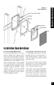
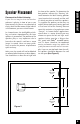
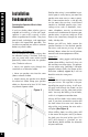
Installation Considerations Figure 1 Model HD8 Shown New Construction Wings Bracket Frame Speaker Baffle IR Knockout Grille Installation Considerations Recommended Amplifier Power For satisfactory performance, we recommend an amplifier with a power rating of five to sixty watts for the MP5; and five to seventy-five watts for the MP6. Curiously, most speakers are not damaged by large amplifiers but by small amplifiers.
Installation Considerations er, so you must connect the wire from the amplifier to the volume control and then from the volume control to the speaker. Speaker Wire Use 2-conductor speaker wire when connecting MP speakers to your receiver or amplifier. For most applications, we recommend you use 16 or 18 gauge stranded wire. For wiring runs longer than 80 feet we recommend 14 gauge stranded wire. The no-strip terminals of the MP speakers will accommodate 12 to 18 gauge wire.
Placement for Critical Listening If you like to imagine that the band or orchestra is playing in front of you as you listen to music, or you are very conscious of clarity, detail and the textures of the individual instruments, you are a critical listener. In a home theater, the intelligibility of dialog and action reproduced by the front speakers is paramount! The position of the speakers plays a very important role in how clear the sound is and how a stereo image is created.
Speaker Placement The Boundary Effect Corners can affect the bass response of the speaker powerfully! This is called the boundary effect. You will emphasize particular bass frequencies and cancel out other bass frequencies when you place speakers close to the wall/ceiling boundary or a corner wall boundary. This can make the speaker sound excessively boomy and inaccurate to some listeners, while to others it just seems like more bass sound.
A single pair of MP loudspeakers, properly placed, can create a very convincing simulation of an array of speakers. If you place them near a hard reflecting surface you can make one pair of speakers sound like several. Create as many reflections as possible by mounting the speaker up high in the wall so that the ceiling will act as a powerful reflector.
Installation Fundamentals Installation Fundamentals Running the Speaker Wire in New Construction If you have doubts about whether you are capable of installing a Niles MP loudspeaker in your walls, consult a Niles dealer or professional installer. They have special tools, techniques, and experience to make the impossible possible. The installer can provide you with an estimate before any work is done. Scheduling and Preparation Plan to schedule the speaker wiring after the electrical wiring is finished.
Pulling the Cable Pull the cable in sections (from the stereo to the volume control, from the volume control to the speaker). Start with the longest sections and use left over wire to complete the short sections. If you plan to pull many rooms at the same time through a central route, walk off the distance to each destination, add a generous fudge factor for turns and other obstacles, then cut off each section so that you have a bundle of wires you can pull at once.
Installation Fundamentals shining a penlight into the wall. If you have access to an attic or basement space you can quickly see which part of the wall space is free of obstructions (See Figure 5). Volume Control Location Speaker Location Figure 4 Stereo Location Identify where all of your electrical, phone, and TV wiring is likely to be and plan to route around it all.
In traditional wood stud/drywall construction you can cut the hole for the speaker and utilize the large hole to auger holes across, up or down the wall for as far as your drill bit will take you. If you have matching paint and take reasonable care in patching you can cut a hatch in the drywall at each stud, run your wire, and patch and touch-up the wall (See Figure7).
Installation of Brackets, Frames and Grilles in New Construction Installation of Brackets, Frames and Grilles in New Construction Stage One: Before Drywall is Hung. Insulating the Wall Cavity. If feasible, fill the wall cavity with insulation at this point. Attach the wings to the bracket by snapping them into the sides of the bracket. The wings can be shortened by breaking them along the scored lines if their length will interfere with a corner or eaves.
Remove the grilles before painting. If you are using spray paint, use two thin coats without any primer. If you are using a compressor and a spray gun, use the finest, most diffuse setting. Practice first on some paper if you have no experience painting with spray paint. If you are using an applicator or brush, and a can of paint, thin the paint first. You do not want to have to poke hundreds of holes in your beautifully painted grilles.
Installation of Brackets, Frames and Grilles in Existing Walls Installation of Brackets, Frames and Grilles in Existing Walls IMPORTANT: Before you cut into any wall, review the sections on running wire and speaker placement. 1. Drill a 1/8” pilot hole just barely through the wallboard or dry wall (1/2” to 5/8” deep in most homes) about an inch below the center of your proposed speaker location (an inch to the side if you are mounting the speaker horizontally).
4. If you are cutting into lath and plaster walls, use masking tape to outline your penciled marks, drill the four corners with a 1/4” bit and use a razor to score the plaster down to the lath beneath. Then use a chisel to remove all of the plaster within the taped outline. Finally, insert a metal cutting blade into a sabre saw and very slowly and carefully saw the lath. Sawing the lath can easily vibrate plaster off the wall.
Figure 13 1. Separate the speaker wire so that at least two inches of each conductor are free. 5. Place the speaker baffle in the frame by inserting the tabs at the base of the speaker baffle into the corresponding holes in the frame and pushing the speaker forward until the snaps engage (See Figure 16). 2. Open the no-strip terminal by applying pressure to the red and black levers until an audible “click” is heard. 3. Insert one unstripped wire fully into the black and one into the red terminal.
1. Stand half way between the two speakers. 2. Play some music with the amplifier or radio set to Mono. 3. Listen to the richness of the bass and the loudness of the sound. Figure 17 Speaker Phase Speaker wire has two conductors. One conductor is attached to the negative (-) terminals and one conductor is attached to the positive (+) terminals of both your speaker and your amplifier. Usually, the wire is marked for your convenience.
Installation of the Speaker and Grille in New or Existing Construction 19 Adjusting the Tweeter The tweeter is housed in a precision adjustment mechanism which enables precise aiming of the directional high frequencies to provide optimum performance. To adjust the tweeter: 1. Carefully grasp the tweeter housing by placing your thumb and forefinger in the indentations provided. 2. Rotate the tweeter housing either clockwise or counter clockwise as required.
Removing The Speaker If the grille is already installed, remove it by using a bent paper clip or the tip of a corkscrew and pulling it away from the frame. Listening at Higher Volumes It requires more power to achieve a reasonable volume of sound in a large room than it does in a small room. It is possible (even if you are not a teenager) to turn the volume so high that the amplifier runs out of power. This creates “clipping” distortion. Clipping distortion makes treble sound very harsh and unmusical.
Specifications Specifications Model MP5 Driver Compliment 5-1/4” Talc-Filled Polypropylene Woofer with Custom Debris Screen and Treated Foam Surround 3/4” Kaladex® Tweeter Housed in a Low Diffraction Precision Adjustment Mechanism Design Principle Infinite baffle for large and varying air volumes Recommended Amplifier Power Five to Sixty Watts per Channel Nominal Impedance 8 Ohms Frequency Response 75 Hz to 20,000 Hz, plus or minus 3dB (on axis) Dispersion Pattern 90 degrees Horizontally or Vertically (plu
Model MP6 Driver Compliment 6-1/2” Talc-Filled Polypropylene Woofer with Custom Debris Screen and Treated Foam Surround Specifications Specifications 3/4” Kaladex® Tweeter Housed in a Low Diffraction Precision Adjustment Mechanism Design Principle Infinite baffle for large and varying air volumes Recommended Amplifier Power Five to Seventy Five Watts per Channel Nominal Impedance 8 Ohms Frequency Response 65 Hz to 20,000 Hz, plus or minus 3dB (on axis) Dispersion Pattern 90 degrees Horizontally or Vertic
23
PLEASE FILL OUT THE WARRANTY REGISTRATION CARD ON THE REVERSE SIDE, DETACH, AND MAIL TO: DETACH HERE Niles Audio Corporation Warranty Registration Dept. P.O.
WARRANTY REGISTRATION CARD Model Purchased___________________________________ _________________________________________________ Serial Number____________________________________________________________________________________ Dealer Name and Location________________________________________________________________________ __________________________________________________________________________________________________ ❑ Dr. ❑ Miss ❑ Mr. ❑ Mrs. ❑ Ms.
Niles Audio Corporation ("NILES") warrants its loudspeaker products to the original purchaser to be free of manufacturing defects in material and workmanship for a period of five years from date of purchase. This Warranty is subject to the following additional conditions and limitations.
Niles Audio Corporation 12331 S.W. 130 Street Miami, Florida 33186 Tel: (305) 238-4373 Fax: (305) 238-0185 www.nilesaudio.com © 2000 Niles Audio Corporation. Patents applied for and pending.