
HIGH DEFINITION Speaker CM5HD, CM6HD, CM8HD


Final Installation in New
or Existing Construction
1. If it is possible to lay a batt of insulation
into the ceiling cavity do so. Remember
to use equal amounts of insulation for
each speaker.
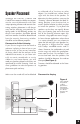
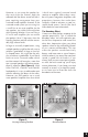
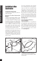
2. Check the position of the Impedance
Jumper on the crossover PC board.
Choose the 4 ohm position if you are
using an amplifier capable of drawing a
4 ohm load and you have only one pair
of speakers connected. Otherwise, use
the 8 ohm position
(See Figure 15).
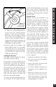
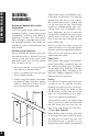
3. Separate the speaker wire so that at least
two inches of each conductor are free.
4. Open the no-strip terminal by applying
pressure to the red and black levers until
an audible “click” is heard.
5. Insert one unstripped wire fully into the
black and one into the red terminal. Pay
attention to the markings on the wire.
Each speaker must be connected to the
amplifier in the same way. If unsure,
see “Speaker Phase” located on the fol-
lowing page. Squeeze the red and black
levers until they click signifying that
they have locked into the wire. Check
to make sure that the knife assembly
inside the no strip connector has prop-
erly pierced the wire
(See Figure 16).
6. Insert the no strip terminal into the
corresponding socket on the rear of
the speaker. Push it down until it locks
in place. The terminal will only fit in
the socket in one direction. If the ter-
minal does not properly seat, reverse
the terminal
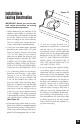
7. On both models, there are four clamps
or mounting “dogs” which hold each
speaker in place. The dogs are tight-
ened via four front-baffle screws. To
install the speaker, first rotate the dogs
inward. Insert the speaker into the
cutout and tighten the dogs by turning
the screws clockwise. DO NOT OVER-
TIGHTEN THESE SCREWS. Over-tight-
ening the clamps may make the grille
difficult to install.
(See Figure 17).
NOTE: The screws will be easier to turn if
you “prime” them first. Before installing each
speaker, turn the screws in and then turn
them back out to their original positions.
8. Direct the Tweeter. The tweeter is
directed by gently pushing on the edge
of the tweeter grille. It will move 20° in
any direction. For critical listening point
the tweeter to the user’s favorite listen-
ing position minimizing reflections from
the side walls. For surround sound or
low volume background listening cre-
ate more reflections and thus more
ambience by directing the tweeter
towards the side walls. See Speaker
Placement on Page 6.
15
Final Installation in New or Existing Construction
Figure 16 No-Strip Speaker Wire Terminal.
Figure 15 Setting the Impedance Jumper.