INSTALLATION & OPERATION GUIDE MM OO DD EE LL SS AT8000 AT8200 ADVANCED TECHNOLOGY IN-WALL LOUDSPEAKERS ® B L E N D I N G H I G H F I D E L I T Y A N D A R C H I T E C T U R E ®
Congratulations! Thank you for choosing Advanced Technology In-Wall Loudspeakers from Niles. With proper installation and operation, you'll enjoy years of trouble-free use. Niles manufactures the industry's most complete line of custom installation components and accessories for audio/video systems. For a free full line catalog write: Niles, Catalog Request, P. O.
The AT or Advanced Technology group of In-Wall Loudspeakers are designed to deliver truly stunning performance with optimum installation flexibility. All models in the AT series are constructed using the highest quality components and utilize advanced materials technology to create speakers capable of reproducing both music and movie soundtracks with stunning realism and sonic impact. They are perfect anywhere that quality of sound is the most important consideration.
Features and Benefits X-Matrix™ Reinforced Baffle The X-Matrix baffle design uses specially molded ribs to add rigidity to the baffle assembly. The end result is better bass and improved midrange detail. Weather Resistant Construction The AT8000 and AT8200 loudspeakers feature drivers which are impervious to moisture; the grille (sold separately as part of the AT8000 Series Frame and Grille kit) is made of aluminum, and all exposed hardware is constructed of stainless steel.
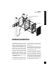
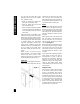
New Construction Wings Bracket Frame Speaker Baffle Installation Considerations Figure 1 Model AT8000 Shown Grille Installation Considerations Recommended Amplifier Power For satisfactory performance, we recommend an amplifier with a power rating of twenty to two hundred watts for the AT8000 and AT8200 speakers. Curiously, most speakers are not damaged by large amplifiers but by small amplifiers. If your system is playing loudly, a small amplifier will run out of power very quickly.
Installation Considerations Speaker Wire Use 2-conductor speaker wire when connecting AT speakers to your receiver or amplifier. For most applications, we recommend you use a minimum of 16 or 18 gauge wire. For wiring runs longer than 80 feet we recommend a minimum of 14 gauge wire. The spring loaded binding post terminals of the AT speakers will accommodate up to 8 gauge wire directly. Banana jack or pin connectors may also be used to allow the connection of larger size wires if necessary.
Insulating the Wall Cavity When it is not possible to use a backbox, good results can be achieved by treating the interior of the drywall cavity with Dynamat™ or a similar cabinet damping material. At least two linear feet of damping material should be adhered to the rear wall and to the front wall (one foot above and one foot below the cutout) of the wall cavity. Additionally, insulating the wall cavity behind the speaker with fiberglass insulation (e.g., R-19 unbatted insulation) will improve performance.
Speaker Placement image is created. Here are some guidelines to make the process of placement quick and easy. Make sure the sound will not be blocked or reflected off of furniture or other objects. You should have a direct line of sight with the front of the speaker. To determine the best position, measure the “listening” distance between the ideal listening position (your favorite chair or couch) and the wall in which you plan to install the speakers.
Placement for Rear Home Theater Applications In a home theater, the goal is to reproduce the experience of a great movie theater in our homes. The biggest difference between the two is the rear or surround speaker array in a commercial theater. Here, it is not uncommon to see twenty or thirty speakers around the audience. This huge array of speakers assures that you will feel completely surrounded by the ambient soundtrack of the movie.
Installation Fundamentals you can avoid wire routes which could potentially induce hum over the speaker wire. The basic rules are: • Never run speaker wire through the same hole as an electrical cable. • Never run speaker wire into the same J-box as electrical cable. • Avoid running the speaker wire beside the electrical cable. Keep it at least three or four feet distant from any electrical power cable.
Concealing Speaker Wire in Existing Walls This is actually a fairly simple task if you restrict your choice of speaker locations and wire routes to the interior walls or ceilings of your home. Interior walls in almost all North American residences are hollow, so that it is easy to flush mount speakers into them and route new speaker cable around the house. What you see when you look at the painted wall board, plaster, or paneling is only the skin of the wall.
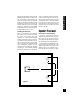
Installation Fundamentals Unobstructed space for speaker wiring Figure 5 route around it all. You can accidentally induce 60 Hz hum on your speakers if you run your speaker wire right beside electrical wire for more than a few feet. Try to keep speaker wire running parallel to power cables at least 3 feet away.
Installation Fundamentals Figure 7 In traditional wood stud/drywall construction you can cut the hole for the speaker and utilize the large hole to auger holes across, up or down the wall for as far as your drill bit will take you. If you have matching paint and take reasonable care in patching you can cut a hatch in the drywall at each stud, run your wire, and patch and touch-up the wall (See Figure 7).
Installation of Brackets, Frames and Grilles in New Construction Figure 8 Installation of Brackets, Frames and Grilles in New Construction Stage One: Before Drywall is Hung 4 Wire Ties Insulating the Wall Cavity. If feasible, fill the wall cavity with insulation at this point. Attach the wings to the bracket by snapping them into the sides of the bracket. The wings can be shortened by breaking them along the scored lines if their length will interfere with a corner or eaves.
Installation of Brackets, Frames and Grilles in New Construction Figure 10 Screw one side of the assembled bracket with wings to the stud using one of the supplied screws. Level the bracket. Screw the other side of the bracket to the stud. Two or three screws (depending upon the size of the model) on each side makes for a very secure installation. Attach the wire to the bracket at the indicated wire tie points (See Figure 9).
Installation of Brackets, Frames and Grilles in Existing Walls Installation of Brackets, Frames and Grilles in Existing Walls Important: Before you cut into any wall, review the sections on running wire and speaker placement. 1. Drill a 1/8” pilot hole just barely through the wallboard or dry wall (1/2” to 5/8” deep in most homes) about an inch below the center of your proposed speaker location (an inch to the side if you are mounting the speaker horizontally).
Installation of the Speaker and Grille in New or Existing Construction Setting the Tone Controls The AT8000 and AT8200 speakers feature baffle-mounted, 4 position level controls for the Bass, Midrange and Treble frequencies. These tone shaping filters enable each of the frequency bands to be cut or boosted to compensate for less than ideal room acoustics, or to suit the listener’s preference.
Installation of the Speaker and Grille in New or Existing Construction Installing the Speaker If the grille is already installed, remove it by using a bent paper clip or the tip of a corkscrew and pulling it away from the frame (See Figure 13). 1. Separate the speaker wire so that at least two inches of each conductor are free. 2. Strip one half inch of insulation from the end of each conductor of the speaker wire. Figure 13 3.
Listening at Higher Volumes It requires more power to achieve a reasonable volume of sound in a large room than it does in a small room. It is possible (even if you are not a teenager) to turn the volume so high that the amplifier runs out of power. This creates “clipping” distortion. Operation Operation Clipping distortion makes treble sound very harsh and unmusical.
Specifications Specifications Model AT8000 Model AT8200 Driver Compliment Driver Compliment WOOFER — 8” Interlaced carbon/glass fiber cone with an inverted dust cap, butyl rubber suspension and a custom construction debris screen WOOFER — 8” aluminum/urethane cone with a high temperature aluminum voice coil former, an inverted dust cap, a butyl rubber suspension and a custom construction debris screen MIDRANGE — 1-1/2” fluid-cooled trilaminate hyperbolic dome with a NDFE 35 neodymium, high magnetic f
Niles Audio Corporation ("NILES") warrants its loudspeaker products to the original purchaser to be free of manufacturing defects in material and workmanship for a period of two years from date of purchase. This Warranty is subject to the following additional conditions and limitations.
WARRANTY REGISTRATION CARD Model Purchased___________________________________ _________________________________________________ Serial Number____________________________________________________________________________________ Dealer Name and Location________________________________________________________________________ __________________________________________________________________________________________________ ❑ Dr. ❑ Miss ❑ Mr. ❑ Mrs. ❑ Ms.
PLEASE FILL OUT THE WARRANTY REGISTRATION CARD ON THE REVERSE SIDE, DETACH, AND MAIL TO: DETACH HERE Niles Audio Corporation Warranty Registration Dept. P.O.
Niles Audio Corporation 12331 S.W. 130 Street Miami, Florida 33186 Tel: (305) 238-4373 Fax: (305) 238-0185 www.nilesaudio.