INSTALLATION & OPERATION GUIDE Systems Integration Amplifier™ ® B L E N D I N G H I G H F I D E L I T Y A N D A R C H I T E C T U R E®
CONGRATULATIONS! Thank you for purchasing the award winning Niles SI-1230, one of the most versatile and powerful multi-channel amplifiers ever offered. Like all Niles products, the SI-1230 is built to the highest standards of quality and reliability. With proper installation and operation, you'll enjoy years of trouble-free use. Niles manufactures the industry's most complete line of custom installation components and accessories for audio/video systems.
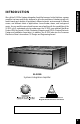
We call the SI-1230 a Systems Integration Amplifier because, for the first time, a power amplifier has been specifically designed to solve the problems of interfacing with different brands and models of equipment, different acoustic environments in different rooms, and different kinds of applications: home theater, stereo, and background music.
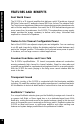
FEATURES AND BENEFITS FEATURES AND BENEFITS Real World Power The SI-1230 is a 12-channel amplifier that delivers a solid 30 watts per channel RMS into 8 ohms and 37 watts per channel RMS into 4 ohms. The massive MultiTap Toroid power transformer features six independent secondary transformers for each of the six amplifier modules. As a result, the SI-1230 delivers twenty percent more power than its predecessor, the SI-1200.
Each channel has its own independent level control enabling you to adjust the volume settings for twelve different speaker locations. Each speaker can be adjusted for its location and who uses it! Turn-On Modes The SI-1230 features three turn-on modes: 1. Manual turn-on via the front panel switch, 2. Audio Sense and 3. External Voltage trigger. Audio Sense and External Voltage trigger modes enable allow you to configure the SI-1230 to interface with any kind of system and turn on automatically.
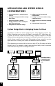
APPLICATIONS AND SYSTEM DESIGN CONSIDERATIONS APPLICATIONS AND SYSTEM DESIGN CONSIDERATIONS 5 System Design Basics—Assigning Rooms to Zones.
CD PLAYER TAPE PLAYER VCR TV A Single-Zone System allows only one source to be heard throughout the house at a given time. RECEIVER FAMILY ROOM LIVING ROOM LISTENING ZONE 1 APPLICATIONS AND SYSTEM DESIGN CONSIDERATIONS A Single-Zone System allows only one source to be heard throughout the house at a given time. However, if the system is configured to be a Multi zone system it would offer the household more flexibility.
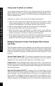
Using Level Controls as Limiters APPLICATIONS AND SYSTEM DESIGN CONSIDERATIONS If your system is remote controlled, or if you think that some of the users like to play the stereo too loudly, you can choose to calibrate the system so that it is limited to a volume level you assign. The SI-1230 allows you to set different volume levels for different rooms. Calibrate your system volume levels with the steps outlined below: 1. Lower all of the SI-1230 level controls to the minimum volume position.
Using Mono For Smoother Coverage 1. 2. 3. 4. 5. Large rooms with many seating areas and/or many pairs of speakers Irregularly shaped rooms Bathrooms with one speaker over the tub and one speaker over the sink(s) Hallways or passageways (even those with multiple speakers) Small rooms where only one speaker will physically fit Adding More than Two Surround Sound Speakers In a home theater, we try to reproduce the experience of a great movie theater in our homes.
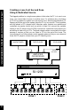
APPLICATIONS AND SYSTEM DESIGN CONSIDERATIONS Creating a Low-Cost Second Zone Using A Dedicated Source The biggest problem in a single zone system is that when the TV is in use in one room, you cannot listen to music in another room. For a listener who only listens to CD’s it is possible to create a low-cost second zone, allowing simultaneous CD listening while the rest of the system plays the TV (or any source).
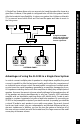
Adding Preamps to Create More Listening Zones AM/FM TUNER TAPE PLAYER CD PLAYER 6 STEREO PREAMPS OR 1 MATRIX PREAMP WITH 6 STEREO OUTPUTS APPLICATIONS AND SYSTEM DESIGN CONSIDERATIONS In the ultimate multi-zone system you would connect six stereo preamplifiers (or a single component multi-zone or matrix preamp) to one SI-1230 and create six completely independent stereo systems. A system like this allows six people to simultaneously listen to different sources.
Surround Sound in Two Rooms APPLICATIONS AND SYSTEM DESIGN CONSIDERATIONS You can easily add a second room of surround sound speakers by connecting five of the SI-1230 channels to the pre-outs of your surround system. If there is a preout/main-in loop, use a "Y" connector as shown so that the internal power amplifier can still be used in the main surround sound room.
Because the SI-1230 offers so many configuration possibilities it is important to plan carefully before you install it. Draw a block diagram of your system and use the Configuration Worksheet on page 29 to record how you plan to connect your SI-1230. Here is an example filled out according to the block diagram on page 11.
INSTALLATION CONSIDERATIONS INSTALLATION CONSIDERATIONS Placement Place the SI-1230 on a flat, level surface like a table or shelf. It should be placed upright so that its weight rests on the unit’s four feet. PLACING THE WEIGHT OF THE AMPLIFIER ON THE REAR OR FRONT PANEL FOR EVEN AN INSTANT WILL RESULT IN DAMAGE TO THE AMPLIFIER'S CONNECTORS AND CONTROLS. The SI-1230, like any hi-fi component, will last much longer if it is given adequate ventilation for proper cooling.
The SI-1230 draws more current than a preamplifier’s switched AC outlet can safely supply. Also, your preamplifier may "thump" at dangerous volumes if the amplifier is already on when the preamp turns on. It is usually best to turn the amplifier on only when it is needed. The Turn-On Mode selector switch gives you three options for turning "On" and "Off" the SI-1230. Constant – The auto turn-on circuitry is off. The front panel master power switch operates the amplifier. In is "On", Out is "Off".
FRONT AND REAR PANEL DETAILS Red “Power” LED confirms the amplifier is connected to a live AC power outlet and that the front panel master power switch is on. Red “Active” LED lights when the amplifier circuitry has been turned on by the Turn-On circuits. Front panel “Master Power” switch turns off the entire amplifier, including the auto turnon circuitry. Main Bus Inputs enable you to route a stereo line level source to the BusMatrixTM of the SI-1230.
hes, BusMatrix controls, dedicated el controls for each channel. Attractive extruded aluminum front panel. FRONT AND REAR PANEL DETAILS Red “protect” LED indicates a fault condition (D.C. output). Gold-plated RCA jacks Serial Number. Dual banana spaced binding posts for speaker connections. Removable Two-prong 16 gauge 6’ AC power cord.
INSTALLATION CONSIDERATIONS 17 Speaker Compatibility CAUTION! Do not use speakers with an impedance of less than 4 ohms with an unbridged channel. Do not use speakers with an impedance of less than 8 ohms with a bridged channel. An unbridged channel of the SI-1230 is designed to play into a speaker load of four ohms or more. When a four ohm speaker is connected, the continuous power rating of the amplifier increases to 37 watts RMS per channel, (all channels driven).
Because the SI-1230 has so many connections on the back panel it is very important that you label all the input cables and speaker wires. If you label the cables and wires for their destination or source, rather than which terminal of the SI-1230 they are connected to, it will be easier to reconfigure your system in the future. The SI-1230 connects to your sources via shielded line level audio cables with RCA phono plugs.
INSTALLATION INSTALLATION 19 Bridging Two Channels into One 23 Line Level Audio Inputs 20 BusMatrixTM Input Switch Setting 23 Cascade Audio Outputs 21 Setting The Turn-On Mode Switch 24 AC Power Plug 21 The Control Output 24 Rail Fuse Holders 22 Speaker Wire Connections CAUTION! ALL CONNECTIONS AND REAR PANEL SWITCH SETTINGS SHOULD BE MADE WITH THE AMPLIFIER’S FRONT PANEL MASTER POWER SWITCH OFF.
STEP DESCRIPTION 2. Connect the speaker wires to the two Bridged speaker terminals (BRIDGED +, BRIDGED -). Observe proper polarity markings. Connect your speaker wire only to the red terminals of the two adjacent amplifier channels. If one of the speaker wires touches a black terminal (thereby grounding the red "hot" terminals) you will short circuit the amplifier. CAUTION! DO NOT connect a speaker selector or headphone junction box to the output of a bridged channel pair.
INSTALLATION Setting the Turn-On Mode Switch The SI-1230 has three turn-on modes. Select the mode you want by sliding the mode switch. See Installation Considerations on page 13 for more information about each of the turn-on modes. Slide the switch with either your fingernail or a 1/8” slotted screwdriver blade. The Control Output This terminal provides a 12V DC signal suitable for triggering Niles automated switchers, some motorized screens, some electric curtain controls, etc.
CAUTION! All speaker wire connections must be made with the amplifier Off. Bare Wire Unscrew the red or black plastic knob, insert the bare wire end into the opening, and then tighten the knob until the wire is securely clamped. Banana Plugs There are many types of banana plugs, some crimp, some solder. The Niles gold banana plug has a quick-connect binding post for the bare wire on the body of the plug. A banana plug is simply inserted into the jack at the end of the amplifier’s binding post.
INSTALLATION Line Level Audio Inputs CAUTION! THE AMPLIFIER MUST BE OFF WHENEVER YOU MAKE CHANGES TO THE INPUT CONNECTIONS. STEP DESCRIPTION 1. Label all of the interconnecting cables for the sources they connect to. Use audio patch cables with RCA phono plugs attached to the ends. 2. Connect the sources by inserting the RCA plug into the amplifier’s jacks. Connect outputs from your sources to inputs on the amplifier. Never connect a source or preamplifier’s input (e.g.
STEP DESCRIPTION Plug the attached 2 prong plug into a correctly grounded 120V 60 Hz wall outlet. If you use a grounded power strip, surge suppressor or extension cord, verify that proper ground is maintained. CAUTION! Do not plug the amplifier's cord into a preamplifier’s convenience outlets. The SI-1230 draws a maximum of approximately 890 watts from an AC wall outlet. This is much more than the typical accessory outlet on the back of a component will provide.
OPERATION OPERATION Power LED The power LED indicates that the AC cord is plugged into a working AC power receptacle and that the power switch is in the "On" position. Active LED The rear panel turn-on mode switch determines when and how the amplifier will turn on. The "Active" LED indicates that the amplifier is on. Power Switch The front panel switch is a master or "vacation" power switch.
If you continue to operate the amplifier at "clipping" power levels the protection circuits will operate when the amplifier overheats. The protection circuits reset when the amplifier's internal circuitry cools. Reduce the volume to prevent a reoccurrence. Perpetually overdriving your speakers and amplifier is abuse and probably voids the manufacturer’s warranty of all affected products. OPERATION Clipping distortion makes treble sound very harsh and unmusical.
TROUBLESHOOTING GUIDE TROUBLESHOOTING GUIDE When there is a problem consult this guide first. If the problem persists, or you have additional questions, call your local Niles dealer or call Niles Technical Support at 1-800-289-4434. The most common problems relate to hook up. SYMPTOM POSSIBLE CAUSES AND TEST PROCEDURE No sound on one channel BusMatrix DIP switch is not in the correct position. Check your configuration worksheet for the correct setting and verify.
Have your configuration worksheet handy when you call. SYMPTOM POSSIBLE CAUSES AND TEST PROCEDURE Hum from all of the speakers Hum may be caused by a ground loop between two components in the system. To test for a ground loop, try reversing the AC plugs of each of the components in the system, that have non polarized plugs. Check for faulty cables, faulty source material, an ungrounded phono system, cable TV feed or a defective component. Amp will not turn on Master power switch must be on.
CONFIGURATION WORKSHEET CONFIGURATION WORKSHEET BUS INS & OUTS CONNECTED TO Left Main Bus Right Main Bus Cascade Output CH # BRIDGED DIP INPUT SOURCE SPEAKER 1 2 3 4 5 6 7 8 9 10 11 12 MODE SETTINGS IN USE SPECIAL CONNECTIONS OR NOTES Constant Audio Sense Voltage Trigger Control Output For ease of use, the Configuration Worksheet can be enlarged on a photocopier.
Design Principle Linear voltage/current amplification. Continuous Power Output (FTC Rated) (unbridged, all channels driven) 30 watts per channel RMS at 8 ohms and 37 watts per channel RMS at 4 ohms. SPECIFICATIONS SPECIFICATIONS Bridged Power Output (Two channels bridged, all channels driven) 80 watts per channel RMS at 8 ohms. Input Impedance 10,000 ohms Input Sensitivity 67mv for 1 watt out; 334mv for full output, (30 watts) level controls set at max. Overall Voltage Gain 32.
Niles Audio Corporation 12331 S.W. 130 Street Miami, Florida 33186 Tel: (305) 238-4373 Fax: (305) 238-0185 www.nilesaudio.com ©1999 Niles Audio Corporation. Because Niles strives to continuously improve its products, Niles reserves the right to change product specifications without notice. Niles, the Niles logo and Blending High Fidelity and Architecture are registered trademarks of Niles Audio Corporation. Systems Integration Amplifier and BusMatrix are trademarks of Niles Audio Corporation.