User's Manual MAXIDRIVE3.4 3 WAY STEREO DIGITAL CROSSOVER R LTO www.altoproaudio.com Version 2.
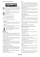
Fuse SAFETY RELATED SYMBOLS To prevent fire and damage to the product, use only the recommended fuse type as indicated in this manual. Do not short-circuit the fuse holder. Before replacing the fuse, make sure that the product is OFF and disconnected from the AC outlet. CAUTION RISK OF ELECTRIC SHOCK DO NOT OPEN This symbol, wherever used, alerts you to the presence of un-insulated and dangerous voltages within the product enclosure.
PREFACE Dear Customer: Thanks for choosing MAXIDRIVE3.4 3 - Way Stereo Digital Crossover and thanks for choosing one of the results of LTO AUDIO TEAM job and researches. For our LTO AUDIO TEAM, music and sound are more than a job...are first of all passion and let us say our obsession! We have been designing professional audio products for a long time in cooperation with some of the major brands in the world in the audio field.
TABLE OF CONTENTS 1. INTRODUCTION .....................................................................................................................................4 2. FEATURES .............................................................................................................................................4 3. CONTROL ELEMENTS .........................................................................................................................4 3.1 The Front Panel 3.2 The Rear Panel 4.
1. INTRODUCTION Your MAXIDRIVE3.4 is a 3-way stereo digital crossover and it is a powerful versatile signal processor. The apparatus will provide 3, 4, 5 or 6-way mono X-over with 6 outputs. Thanks to the use of selected and expensive components, the performances of MAXIDRIVE3.4 are worth much more than its price: you can set the input and output routing configuration only through recalling one of the Presets included in the internal memory. 2. FEATURES Single rack unit Delay lines up to 2.
7.Memory Card Slot The Slot allows you to insert the Memory Card which is very useful for safe storage of PRESETS and for their transfer from one MAXIDRIVE3.4 to another. 8.ENTER key The key allows you to access to the selected editing page. Pressing this key, you can edit and confirm the required value of parameter. 9.ESC key The key allows you to exit the selected editing page. It also used to reject the value to enter and return to the stored value. 10.
16.RS485 OUT This is the standard serial communication interface port. It allows outgoing communication between a MAXIDRIVE3.4 and PC or other MAXIDRIVE3.4 units. The RS485 interface is very suitable for remote control over long distances (difficult with RS232 standard ports) and daisy-chaining several MAXIDRIVE3.4. 17.RS485 IN The function of the RS485 IN port is opposite to RS485 OUT. It allows incoming communication between a MAXIDRIVE3.4 and PC or other MAXIDRIVE3.4 units.
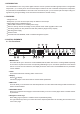
And the system Will enter into default status, showing the main operating information on the display. A 1 3 B24 S 5 6 2 F 2 x 2W+ 2 MAX Set all the MAXIDRIVE3.4 outputs in MUTE status (LEDs lit) by pressing the relative keys. Load the Factory PRESET containing the configuration you've found. Press the MODE Key until the PRESET menu LED lights up.
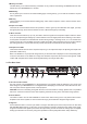
I NA GA I N I NA&B GA I N 0 . 0 dB 0 . 0 dB Use the DIAL to change the gain value and watch the level of the signal on the LED ladders until the ideal values are reached. I NA GA I N I NA&B - 2 . 5 dB GA I N + 6 . 0 dB Then use the PREV and NEXT keys to access to the INB Gain page (if there is one, this will depend on the configuration and the other utilities loaded in the memory). Repeat the settings as explained above. 4.3 First Setup At this point, the first custom setup can be prepared.
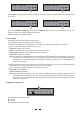
Numbers 1, 2, 3, 4, 5 and 6 indicate the respective outputs. In the example: The signal connected to Input A is assigned to outputs 1 and 3. The signal connected to Input B is assigned to outputs 2 and 4. The Sum of the signal on inputs A and B is assigned to outputs 5 and 6. The system is therefore configured as shown in the following diagram.
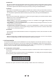
4.8 PRESET Modifications M A 1 3 B24 S 5 6 2 U 2 x 2W+ 2 MAX This indicates that the value of one or more parameters has been temporarily modified with respect to the stored in the PRESET shown. Practically speaking, this indication means that the changes made to the PRESET have not been stored. Note: once it has been enabled, the indication remains even if the "original" values are reset manually.
There are 3 distinct categories of PRESETS: Factory PRESETS Factory-programmed storage. Factory PRESETS can be used normally, temporarily modified, but can't be cancelled, overwritten or permanently modified. Factory PRESETS contain some specific settings for certain types of enclosures and all the system's usable configurations. For this reason they're the ideal starting point for creating custom PRESETS. User PRESETS Stored data that can be programmed by users.
Note: In the example, Factory PRESET #3, named "2x3W" has been loaded: Its system configuration is Input A signal assigned to outputs 1, 3 and 5; Input B signal assigned to outputs 2, 4 and 6. Loading a PRESET, a PRESET Change command is also automatically sent to the serial ports and can be used to automatically load a PRESET with the same number to any other MAXIDRIVE3.4 units connected and enabled (Refer to UTILITY menu - Comm. Setup submenu - PRESET Change RX option). 5.1.
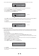
P r e s e t Nam i n M 2 W+ 2 MA X 5.1.3 Dump Out PRESET Use this menu page to download a PRESET via the serial ports. It is also used to immediately "copy" the settings of the various PRESETS of a MAXIDRIVE3.4 to another MAXIDRIVE3.4. D um Ou t P r e s e t + x MA X 2 W 2 2 U2 To download a PRESET: Use DIAL to reach the required PRESET. Press ENTER. Note: The menu page remains unchanged to allow other PRESETS to be dumped. All the Preset s data (name, configuration, parameter values, etc.
Ignore the data received via the serial ports. I n c om i n g Accept the data received via the serial ports. D ump I g n o r e I n c om i n g D ump Ac c e p t 5.2.Delay Menu Use this menu to work on the systems delay lines. menu DELAY Input Delay Parameters Output Delay Parameters Parameters In these pages, the number of the parameters and how they are presented varies according to the configuration of the PRESET and according to Ganging and Units settings (UTILITY menu).
Output Delay only delays the signal of a specific output. Also called Channel Delay, output delay is mainly used to compensate for the distance between different blocks of the same sound system (for example clusters) or to correct internal alignment of a speaker enclosure components. 5.2.1 Input Delay Use this menu page to adjust the delay lines of Input A, Input B and SUM.
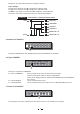
The values can be set in the following ranges: 0P1 OUTPUT DELAY D E LAY 2 9 2 uS unit range step m 0.0 ~ 100.0 0.5 mm 0 ~ 100000 7 ms 0 ~ 291 1 us 0 ~ 291271 21 The values can be set in the following ranges: OUTPUT DELAY OUTPUT 1 HIGH OUTPUT DELAY Loudspeaker Components OP1 DELAY= 0ms Delayed Virtual Alignment #1 Delayed Virtual Alignment #2 18ms(6 5m) 4ms 14ms(5m) OUTPUT 3 LOW OP3 DELAY= 4ms 5.
I n p u t Ga i n Allows to adjust the amplification of the signal fed in through Inputs A and B. Editing values are in the range +6dB ~ -30dB, with 0.5dB steps. I NA GA I N - 2 . 5 d B Note: Setting the input signal of a digital unit is particularly important, much more than on an analog unit, as any saturation of the A/D converter due to an excessively high input signal causes a typical particularly distinct noise. To achieve a good signal/noise ratio, i.e.
b. Centre Frequency / Cutoff Frequency Allows to choose the centre frequency of the Peaking curve and Notch filter, or the cutoff frequency of Shelving curves. I NA 2 k 0 0 EQ1 1 . 0 Low Shelving Peaking Pe a k - 5 . 0 High Shelving Notch c. Bandwidth Allows to choose the width in octaves of the Peaking or Notch type curve. It s not used with Shelving curves. I NA 2 k 0 0 EQ1 1 . 0 Pe a k - 5 . 0 Notch Peaking d. Gain Allows to control the boost or cut of the selected frequencies.
The values can be set in the following ranges: ~ ~ ~ 5.3.3 Xover Low-pass and high-pass filters. Made up of a combination of a low-pass filter and high-pass filter, the crossover allows to divide the audio signal into segments that can be used by the individual section of a sound system (for example High, Mid & Low). X o v e r Each Xover has 2 slightly different pages (one for each filter), where the name of the output it affects and the type of filter are shown.
Each filter has the following editable parameters: Type of filter Allows to choose three different types of filter and different attenuation slopes: Butterworth (But) at 6, 12, 18 or 24dB per octave, Bessel (Bes) at 12, 18 or 24dB per octave, Linkwitz-Riley (LR) a 12, 24 or 48dB per octave. By setting the Thru value, the filter is disabled and the signal passes without its frequency being altered. LPF OP1 2 k 0 0 H z Be s 2 4 0 Crossover frequency Allows to choose the filter cutoff frequency.
5.3.4 Output EQ Output equalizer with 5 parametric filters. Also called Channel EQ, allows to alter the tone of each individual output. The characteristics of quality and programmability are identical to those of the Input Equalizer and enable this unit to be used extremely effectively and flexibly. Ou t pu t EQ Each equalizer has 5 pages (one per filter), indicating the name of the output it effects and the number of the filter. OP1 2 k 0 0 EQ1 1 . 0 Pe a k + 1 .
Normal: leaves the phase unchanged OP1 Reverse: shifts the phase through 180 , inverting it. OP1 POLAR I TY N o rma I POLAR I TY Re v e r s e The effect of this control is summed with that of the parameter of the LPF filter (Xover - EDIT menu), which operates with 5 steps in a range of between 0 and 180 .
IMPORTANT! Enabling the LIMITER on a specific output also changes the way in which the level is displayed on the corresponding LED ladder: In fact, the level shown on this ladder is no longer the "absolute" output level, but the level of the signal at -24dB, -12dB, -6dB compared to the LIMITER's threshold (orange LIMIT LED), no matter what the threshold value is. 5.
Ga n g i n g The practical use of the Ganging function consists in the possibility of editing with identical values the parameters of similar elements, carrying out single (instead of double) operations. For example, it's possible to set the same Delay value or equalization on both inputs with just one operation; or set identical Xover parameters for the various outputs fed to a stereo sound system; or yet again, enable the LIMITER simultaneously on the two outputs dedicated to two mono stage monitors.
b. Output Ganging Used to enable/disable Ganging function on the outputs. The settings are: Disabled Ou t p u t Enabled Gan g i n g O f f Ou t p u t Gan g i n g On 5.4.2 UNITS SUBMENU Units Delay Unit Lim. Thresh. Unit Temperature Unit Used this submenu to choose the measurement units to be used with certain functions. Un i t s a. Delay Unit Used to set the measurement units in which Delays are expressed (DELAY menu).
5.4.3 Misc. Setup submenu Misc. Setup Input Select Output Meters Temperature Wake Up LCD Contrast Use this submenu to set a series of system options. M i s c . S e t u p a. Input Select Used to choose inputs which MAXIDRIVE3.4 should use.
c. Temperature Used to key in the value of the environmental temperature of place of installation. The system uses this value to automatically compensate for the differentials due to the difference speed of sound Transmission according to the air temperature. This allows to set the delays during the sound-check and only have to reset them automatically when necessary (For example during a concert, in the event of big jumps in temperature, etc.).
Lo ck This function is very useful whenever even temporary changes or tampering with the settings stored in the system must be prevented. For example: fixed installations used by several operators (discotheques, clubs, conference halls, etc.), sound system rental, etc.
T M A1 3 B2 4 S 5 6 2 U2 2W + 2 MA X Note: alongside the symbol of Total or Partial protection, the letter M may also appear. This means that the system is protected, but the PRESET in question has undergone one or more changes that have not yet been stored. You can however switch the system on and off without any problems, as the current settings are kept in the buffer memory. Nevertheless, if this is your work setup, it's advisable to store it in a PRESET.
ATTENTION! Formatting cancels any data contained in the Card. In the Memory Card submenu, press ENTER. The Format Card page appears F o r ma t C a r d Press ENTER. The system formats the Card until it communicates that it has completed. This operation only requires a few seconds. The Card is ready to be used. C a r d F o r ma t F o r ma t t i n g . . .
The PRESET Change command is completely identical to MIDI Program Change: the transmitting unit sends an instruction containing a number of PRESETS to load; the receiving units (if they are able to accept the command) each loads into its own memory the PRESET with the corresponding number. This means that, in a chain of MAXIDRIVE3.
Outputs 1 ~ 6, RS485 OUT 2 HOT (+) 3 BALANCED XLR-F 1 COLD ( ) GROUND RS232 PIN 5 PIN 3 PIN 2 RS232 (9Pin-F) (TXD) PIN2 (RXD) PIN3 (GND) PIN5 PIN 3(RXD) PIN 2(TXD) PIN 5(GND) 9 PIN 9 PIN The wire must be changed between 2,3 pin. Special attentions for RS232 interface: 1. Be careful not to use the pin-to-pin cable in the system, it may damage the communication part of this unit. 2. Be sure to use the female connector on both sides of the cable. 3.
7.2 Organization The following examples will help you well use and connect the unit. a.
b.
c.
d.
e. Communications: PC & one or more MAXIDRIVE3.4 connection to / from RS232 Serial Port MAXIDRIVE3.
8. TECHNICAL SPECIFICATIONS INPUT section Connectors Nominal input sensitivity Input Impedance Maximum Input Level Input Gain Digital input Digital input sample rate 2 x COMBO 0 dB (0.775 V) 30kOhm, electronically balanced +20dBu -30 / +6 dB variable in 0.
9. WARRANTY 1. WARRANTY REGISTRATION CARD To obtain Warranty Service, the buyer should first fill out and return the enclosed Warranty Registration Card within 10 days of the Purchase Date. All the information presented in this Warranty Registration Card gives the manufacturer a better understanding of the sales status, so as to purport a more effective and efficient after-sales warranty service.
SEIKAKU TECHNICAL GROUP LIMITED No. 1, Lane 17, Sec. 2, Han Shi West Road, Taichung 40151 Taiwan http://www.altoproaudio.com Tel: 886-4-22313737 email: alto@altoproaudio.com Fax: 886-4-22346757 All rights reserved to ALTO. All features and content might be changed without prior notice. Any photocopy, translation, or reproduction of part of this manual without written permission is forbidden. Copyright c 2005 SEIKAKU GROUP NF 01131-2.