Manual Steering Models SCRUBTEC R 571 SCRUBTEC R 571 C SCRUBTEC R 586 SCRUBTEC R Operator's Manual U.S. Patent No. 6,105,192; No. RE39,581; No. 6,557,207; No. 7,185,397; and Patents Pending READ THIS BOOK CAUTION: Read the Operator's Manual before using the appliance. This book has important information for the use and safe operation of this machine.
Table of Contents Operator Safety Instructions .................................................................................................................................................. Introduction & Machine Specifications .................................................................................................................................... Symbols Used on Scrubtec ..........................................................................................................................
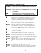
OPERATOR SAFETY INSTRUCTIONS DANGER: Failure to read and observe all DANGER statements could result in severe bodily injury or death. Read and observe all DANGER statements found in your Owner's Manual and on your machine. WARNING: Failure to read and observe all WARNING statements could result in injury to you or to other personnel; property damage could occur as well. Read and observe all WARNING statements found in your Owner's Manual and on your machine.
WARNING: Any alterations or modifications of this machine could result in damage to the machine or injury to the operator or other bystanders. Alterations or modifications not authorized by the manufacturer voids any and all warranties and liabilities. WARNING: Electrical components of this machine can "short-out" if exposed to water or moisture. Keep the electrical components of the machine dry. Wipe the machine down after each use.
English Correct Disposal of This Product (Waste Electrical & Electronic Equipment) (Applicable in the European Union and other European countries with separate collection systems) This marking shown on the product or its literature, indicates that it should not be disposed with other household wastes at the end of its working life.
Symbols Used On Scrubtec R Forward / Reverse Brush Up/Down Squeegee Up/Down Horn Solution Flow Switch Battery Meter On/Off Switch Recovery / Solution LED WARNING LCD Display Button READ OPERATOR'S MANUAL BEFORE OPERATING THIS MACHINE RISK OF FIRE • Use only commercially available floor cleaners and waxes intended for machine operation. • Do not use flammable materials. One Touch Button Page -6- RISK OF INJURY OR DAMAGE TO MACHINE • Do not turn, stop or leave machine on a ramp or dock.
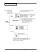
Display Screens For Scrubtec R Position arrow indicating current position of squeegee (up or down) Traverse speed indicator 1 = low 0-3 KPH 2 = med 0-5 KPH 3 = high 0-6.4 KPH Indicators are on, showing current settings. SCREEN 1 Water “droplets” off when solution is off and they are flashing when solution is on. Screens Available to Operator “Battery” blinks when low voltage occurs. Arrows indicating vacuum status. They are flashing when vac is on and off when vac is off.
Machine Control Panel On/Off Key Switch (See figure 1, Item D) The key switch turns “ON” the power to the control panel. “O” is the “OFF” and “I” is the “ON”. Brush Up/Down Switch (See figure 1, Item A) To lower brush head, push the brush switch in the down (+) position. To lower the brush head to maximum brush pressure, continue to hold the switch in the down (+) position until the travel stops.
Machine Controls and Features Recovery Tank Float The Scrubtec R is equipped with a float that shuts the vacuum off when the recovery tank is full. The squeegee will no longer pick up water. If this should happen, raise the squeegee and empty the recovery tank. The Traverse The Scrubtec R is equipped with an electronically controlled traverse system with variable speeds in forward and reverse. 1.
How To Prepare the Machine For Operation How To Handle the Packed Machine The machine is packed in a specific package provided on a pallet so that it can be moved with a forklift. WARNING: BATTERY CONNECTIONS The packages cannot be placed on top of each other. Front of machine How to Unpack the Machine 1. Remove the outer package. 2. The machine is fixed on the pallet with banding straps and wooden blocks to prevent movement during shipment. Remove the bands and blocks. 3. Remove tie down brackets.
How To Prepare the Machine For Operation Battery Maintenance The electrical power to operate the machine comes from the storage batteries. Storage batteries need preventative maintenance. Correct Fill WARNING: Working with batteries can be dangerous. Always wear eye protection and protective clothing when working near batteries. NO SMOKING! To maintain the batteries in good condition, follow these instructions: 1. Keep the electrolyte at the correct level.
How To Prepare the Machine For Operation How to Charge the Batteries WARNING: Charging the batteries in an area without adequate ventilation could result in an explosion. To prevent an explosion, charge the batteries only in an area with good ventilation. WARNING: Lead acid batteries generate gases which could explode. Keep sparks and flames away from batteries. NO SMOKING! CAUTION: See Charger Owner’s Manual. All onboard battery chargers are programmed for a specific type battery.
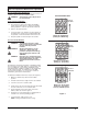
How To Prepare the Machine For Operation Level Indicators for the Charge of the Batteries The battery meter ( see figure 7) on the control panel has a digital read out with 10 fixed positions (A) and also a blinking indicator (B). The bars that appear on the display show the approximate charge level with icon (blinking) discharged battery. A NOTE: A few seconds after the voltage reads 32V it will start blinking. The brush motors will then automatically switch off.
How To Prepare the Machine For Operation How To Change or Rotate Brushes on Cylindrical Brush Head To install or rotate brushes on the cylindrical brush head: 1. Raise the brush deck and turn the key switch “OFF”. 2. Raise the brush skirt and pull out to remove. See figure 11. 3. Remove thumb screw from brush door. See figure 12. 4. Lower door approximately 12 mm and slide door and hub assembly from brush. See figure 13. Figure 11 5. Slide brush off hub at opposite end. See figure 14. 6.
How To Prepare the Machine For Operation How To Install The Brush Or Pad on the BOOST machine To install the brush or pad on the BOOST machine, follow this procedure: 1. Turn the key switch "ON". 2. Put the brush switch in the "UP" position. 3. Turn the key switch "OFF". 4. Go to the side of the machine. 5. Press on a brush or pad under the flex plates. See figure 15. Figure 15 NOTE: When using a black pad, position pad on head.
How To Operate The Machine How to Return One Touch to Factory Default Settings To restore the factory settings, follow the procedures below: 1. Press and hold the green one touch button (figure 17) until you hear a double beep from the machine. NOTE: The time required for this will be approximately 15 seconds. 2. The settings should be returned to 2 bars of solution and 1 bar of brush pressure. NOTE: The squeegee vac switch must be in the middle position for default settings to work.
How To Operate the Machine SCREEN 1 How to Read the Battery Meter (see figure 21, A) The battery meter is an indicator on the LCD display. This indicator is on the LCD display on the front of the machine. It has 10 bars with 10 bars visible indicating a full charge. As you run the machine the bars will begin to lower. The “Battery Icon” (B) will begin to flash to indicate you are reaching the end of charge.
How To Operate the Machine How to Operate the Squeegee and the Vacuum Motor The squeegee wipes the floor while the vacuum motor removes the dirty solution from the floor. To operate the squeegee, follow this procedure: 1. To lower the squeegee and start the vacuum motor, press the squeegee up/down switch to the down position (figure 24). NOTE: The vacuum motor will start immediately when the down position of the switch is pressed, and the squeegee will lower. 2.
How To Operate the Machine How to Operate the Forward / Reverse Switch (see figure 28). 1. To go forward, push the up arrow side of the switch. 2. To go in reverse, push the down arrow side of the switch. How to Fill the Solution Tank The solution tank fill port is located at the left side of the machine (see figure 29). To fill the solution tank, follow this procedure: 1. Turn the key switch to the “OFF” position. 2. Remove lid. 3. Add a cleaning chemical to the solution tank.
How To Operate the Machine (cont.) To traverse the machine follow this procedure: 1. Sit on the driver seat. NOTE: The machine will not traverse if the operator is not properly seated. 2. Turn the key switch to the “ON” position. 3. Raise the brush to the highest position (if necessary). 4. Raise the squeegee (if necessary). 5. Gently press the foot pedal and the machine will begin to move. 6. To stop, release pressure on the foot pedal. 7.
How To Operate the Machine How to Clean a Floor WARNING: Water solutions or cleaning materials used with this type of machine can leave wet areas on the floor surface. These areas can cause a dangerous condition for the operator or other persons. Always put CAUTION signs near the area you are cleaning. For one touch automatic cleaning follow this procedure: 1. Turn the key switch to the “OFF” position. 2. Put the water and a cleaning chemical in the solution tank. 3. Sit on the driver seat.
How To Operate the Machine How to Clean a Very Dirty Floor To clean a very dirty floor, follow this procedure: 1. Apply solution to the floor. 2. Do not lower the squeegee. This will keep the vacuum motor off. 3. Lower the brush or pad and scrub the floor. 4. Scrub the floor again with additional solution and lower the squeegee. 5. Pick up all the solution with the squeegee.
How To Operate the Machine 11. Rinse the tank. Put clean water in the tank through the opening at the top. Be careful not to allow water into the vacuum intake tube (with screen). A B 12. If the tank or recovery hose has an obstruction, use water pressure to flush them. Put the water hose into the recovery hose (figure 35, A). NOTE: Do not place water hose in vacuum intake tube (see figure 35, B), damage will occur.
Maintenance Maintenance To Be Done Every Week WARNING: Maintenance and repairs must be done by authorized personnel only. Always empty the solution tank and the recovery tank before doing any maintenance. Keep all fasteners tight. WARNING: Always wear eye protection and protective clothing when working near batteries. NO SMOKING! Do not put tools or other metal objects across the battery terminals or the tops of the batteries.
Maintenance 5. Clean the hose fitting in the recovery tank and spray water down the squeegee hose to clean out debris. 6. Reattach the squeegee hose. Cleaning the Solution Tank and Filter 1. Move the machine so that the solution tank filter assembly is located directly over a floor drain. 2. Turn the key switch to the “OFF” position. 3. Clean inside the solution tank with a jet stream of water. 7. Close the solution flow valve. 8. Clean the filter inside the housing and reinstall on machine.
Maintenance Rear Squeegee Blade Replacement If the rear squeegee blade is worn and does not dry the floor well, follow this procedure: 1. Remove the squeegee assembly from the machine. 2. Remove the squeegee blade and inspect it. 3. Rotate the squeegee blade to obtain a new cleaning edge. Replace if necessary. Figure 40 4. Reinstall the squeegee blade. 5. Reinstall the squeegee assembly on the machine. A 6. Readjust the settings on the squeegee as required (see “How to Adjust Squeegee”).
HOW TO CORRECT PROBLEMS IN THE MACHINE PROBLEM Insufficient water onto the brushes The machine does not clean satisfactorily CAUSE ACTION The solution flow is not set Make sure the solution flow is set. There is no water in the solution tank. Fill the solution tank. The solution filter is dirty. Clean the solution filter. A circuit breaker has tripped. Reset the circuit breaker. Insufficient flow. Increase flow with solution switch. The brushes are worn.
Scrubtec R Common Error Codes ERROR CODE Page -28- CAUSE ACTION 1500 1501 1507 Check brake and wiring for short circuit. Make sure manual override is not engaged. 1600 High battery voltage. Poor or corroded connection to the battery. 3100 3101 3102 3103 3104 3105 Probable short circuit of output device. Check the traction, brush and vac motor connections on the trio and check wiring from these connectors down to the traction, brush and vac motors.
Accessories and Options BRUSHES AND PAD DRIVERS PART NO. 17521C 10383A 11431B 11426B 11427B 10874A PART NO. 17520C 10384A 11430B 11425B 11424B 10875A PART NO. 30614A 30615A 30616A 30617A 30619A PART NO. 997004 997003 997005 997007 SCRUBTEC R 571 Disc Model DESCRIPTION Pad Driver Assembly (2 req.) Lite Grit Disc Brush (2 req.) Clean Grit Abrasive (2 req.) Supergrit (2 req.) Polypropylene (2 req.) Nylon (2 req.) SCRUBTEC R 586 Disc Model DESCRIPTION Pad Driver Assembly (2 req.) Lite Grit Disc Brush (2 req.
NOTES Page -30- CLARKE TECHNOLOGY Operator's Manual - SCRUBTEC R Manual Steering
Manual Steering Models SCRUBTEC R 571 SCRUBTEC R 571 C SCRUBTEC R 586 SCRUBTEC R Section II Parts and Service Manual (71274A) U.S. Patent No. 6,105,192; No. RE39,581; No. 6,557,207; No.
CLARKE TECHNOLOGY SCRUBTEC R 571, 586, 571 C, BOOST® R Final Assembly Drawing 10/06 13 3 1 12 14 2 4 5 15 11 6 10 9 8B Page -32- 7 8 8A CLARKE TECHNOLOGY Operator's Manual - SCRUBTEC R Manual Steering
CLARKE TECHNOLOGY SCRUBTEC R 571, 586, 571 C, BOOST® R Final Assembly Parts List 10/06 Ref 1 Qty Qty Rotary Cyl. 1 - Qty. Boost - Part No. pg 44-45 Description Tank, Recovery (Assembly) pg 44-45 Tank, Recovery (Assembly) - 1 1 pg 46-49 Tank, Solution (Assembly) - - 1 pg 46-49 Tank, Solution (Assembly) 1 1 - pg 62 Plate, Electrical (28”) 1 - - pg 62 Plate, Electrical (34”) 1 - - pg 62 Plate, Electrical (Cyl.
CLARKE TECHNOLOGY SCRUBTEC R 571, 586 Main Frame Assembly Drawing (Rotary) 9/06 Drawing #11098A 3 2 1 27 4 1A, 1B 26 25 5 6 24 7 6 23 7 22 21 8 20 19 9 18 10 6 17 7 16 15 14 42 42 41 7 41 6 5 11 12 13 40 28 38 29 39 30 41 31 38 A Page -34- See Detail A 22 37 36 22 34 35 35 33 32 32 CLARKE TECHNOLOGY Operator's Manual - SCRUBTEC R Manual Steering
CLARKE TECHNOLOGY SCRUBTEC R 571, 586 Main Frame Assembly Parts List (Rotary) 5/07 Drawing #11098A Ref 1 1A Part No. Description 53386B Actuator, Head Lift 40910A Potentiometer & Circuit Borad 1B 2 40866A 766780 Housing Potentiometer Pin, Hair 1 1 3 4 82501A 40889A Pin, Clevis Horn 1 1 5 6 962288 170883 Bolt, 3/8-16 x 1 Hex Hd Washer, Lock 3/8” 8 22 7 8 980645 53760A Washer, 3/8” S.A.E. Flat Steering Asm.
CLARKE TECHNOLOGY SCRUBTEC R 571C Main Frame Assembly Drawing 9/06 Drawing #10949S 2 1 3 4 26 3A, 3B 25 24 23 5 12 11 16 22 6 21 7 8 9 10 20 11 19 12 13 18 17 16 11 15 12 14 36 33 34 35 34 34 31 27 33 28 32 29 See Detail A 31 30 9 A Page -36- CLARKE TECHNOLOGY Operator's Manual - SCRUBTEC R Manual Steering
CLARKE TECHNOLOGY SCRUBTEC R 571C Main Frame Assembly Parts List 9/06 Drawing #10949S Ref 1 2 3 3A 3B 4 5 6 7 8 9 10 11 12 13 14 15 16 17 18 19 20 21 22 23 24 25 26 27 28 29 30 31 32 33 34 35 36 Part No.
CLARKE TECHNOLOGY SCRUBTEC BOOST® R Main Frame Assembly Drawing 3/08 Drawing #11107A 2 1 3 2A, 2B 17 16 4 15 14 5 7 6 6 13 7 12 12A,12B 11 8 10 9 7 6 5 29 28 27 26 Page -38- 25 24 23 22 21 20 19 18 CLARKE TECHNOLOGY Operator's Manual - SCRUBTEC R Manual Steering
CLARKE TECHNOLOGY SCRUBTEC BOOST® R Main Frame Assembly Parts List 3/08 Drawing #11107A Ref 1 2 2A 2B 3 4 5 6 7 8 9 10 11 12 12A 12B 13 14 15 16 17 18 19 20 21 22 23 24 25 26 27 28 29 Part No.
17 16 1 15 2 3 12 4 14 5 6 6 13 12 7 11 10 9 8 CLARKE TECHNOLOGY SCRUBTEC R 571, 586 Optional Side Squeegee Lift Assembly Drawing 5/05 Page -40- CLARKE TECHNOLOGY Operator's Manual - SCRUBTEC R Manual Steering
CLARKE TECHNOLOGY SCRUBTEC R 571, 586 Optional Side Squeegee Lift Assembly Parts List 5/05 Ref 1 Part No. 87624A Description Washer, Nylon 1 1/2 x 1/4 x 1/8 2 3 86004A 920296 Screw, 1/4-20 x 1.50 HHCS Nut, 10-24 Elastic Stop 1 1 4 5 61699A 962798 Bracket, Sq.
CLARKE TECHNOLOGY SCRUBTEC R 571, 586, 571 C, BOOST® R Front Wheel Assembly Drawing and Parts List 6/07 Drawing #10779A 15 1 3 14 2 4 5 13 6 12 11 10 9 Ref 1 2 3 4 5 6 7 8 9 10 11 12 13 14 15 Part No. 80267A 61472A 980645 170883 85822A 80268A * 81221A 61382A 61691A* * * 85838A 61877A 61878A 8 Description Bolt, 3/4 - 16 Hex Head Yoke Weldment, Steering Washer, 3/8 Flat Washer, Lock 3/8 Screw, 3/8 -16 x 7/8 Hex Hd. Nut, .
CLARKE TECHNOLOGY SCRUBTEC R 571, 586, 571 C, BOOST® R Squeegee Lift Assembly Drawing and Parts List 4/06 Drawing #10787A 3 5 4 6 7 8 9 2 1 10 16 11 12 29 13 28 27 30 26 14 25 15 24 16 17 23 Ref 1 2 3 4 5 6 7 8 9 10 11 12 13 14 15 Part No.
CLARKE TECHNOLOGY SCRUBTEC R 571, 586, 571 C, BOOST® R Recovery Tank Assembly Drawing 6/07 Drawing #10783A & 10990A 1 2 3 4 5 6 7 8 9 10 11 44 43 42 12 41 13 40 14 39 15 38 37 16 17 20 22 18, 18A 19 36 23 21 6 24 35 25 34 26 30 33 29 32 Page -44- 28 27 26 31 CLARKE TECHNOLOGY Operator's Manual - SCRUBTEC R Manual Steering
CLARKE TECHNOLOGY SCRUBTEC R 571, 586, 571 C, BOOST® R Recovery Tank Assembly Parts List 6/07 Drawing # 10783A & 10990A Ref 1 2 3 4 5 6 7 8 9 10 11 12 13 13 13 14 15 16 17 18 18A 19 20 21 22 23* 24* 25* 26 27* 28 29 30* 31 32 33 34 35 36* 37* 38* 39 40 41 42* 43 44 NI NI Part No.
CLARKE TECHNOLOGY SCRUBTEC R 571, 586, 571 C, BOOST® R Solution Tank Assembly Drawing (View 1 of 2) 11/06 Drawing # 11099A 1 26 2 3 4 5 6 24 10 7 2 23 2 8 5 22 21 9 20 10 3 19 18 Page -46- 17 16 15 14 13 12 11 CLARKE TECHNOLOGY Operator's Manual - SCRUBTEC R Manual Steering
CLARKE TECHNOLOGY SCRUBTEC R 571, 586, 571 C, BOOST® R Solution Tank Assembly Parts List (View 1 of 2) 5/07 Drawing # 11099A Ref 1 2 3 4 5 6 7 8 9 10 11 12 13 14 15 16 17 18 19 20 21 22 23 24 26 NI NI Part No.
CLARKE TECHNOLOGY SCRUBTEC R 571, 586, 571 C, BOOST® R Solution Tank Assembly Drawing (View 2 of 2) 9/06 Drawing # 11099A 2 1 3 4 5 6 19 7 8 18 9 10 11 12 17 13 14 15 16 Page -48- CLARKE TECHNOLOGY Operator's Manual - SCRUBTEC R Manual Steering
CLARKE TECHNOLOGY SCRUBTEC R 571, 586, 571 C, BOOST® R Solution Tank Assembly Parts List (View 2 of 2) 9/06 Drawing # 11099A Ref 1 2 3 4 5 6 7 8 9 10 11 12 13 14 15 16 17 18 19 Part No.
CLARKE TECHNOLOGY SCRUBTEC R 571, 586, 571 C, BOOST® R Steering Column Assembly Drawing 5/07 Drawing # 11087B 1 2 3 4 50 5 49 48 6 47 7 46 8 45 51 9 44 10 52 43 42 53 41 54 40 11 12 13 14 55 39 15 56 16 38 37 17 18 19 36 20 35 21 22 34 23 24 33 25 26 27 28 29 32 31 Page -50- 30 CLARKE TECHNOLOGY Operator's Manual - SCRUBTEC R Manual Steering
CLARKE TECHNOLOGY SCRUBTEC R 571, 586, 571 C, BOOST® R Steering Column Assembly Parts List 5/07 Drawing # 11087B Ref 1 2 3 4 5 6 7 8 9 10 11 12 13 14 15 16 17 18 19 20 21 22 23 24 25 26 27 28 29 30 31 32 33 34 35 36 37 38 39 40 41 42 43 44 45 46 47 48 49 50 51 52 53 54 55 56 Part No.
CLARKE TECHNOLOGY SCRUBTEC R 571 571 Rotary Brush Head Assembly Drawing and Parts List 3/08 Drawing #10697A 5 2 3 4 1, 1A, 1B, 1C 6 28 7 8 29 9 11 10 27 12 26 13 25 30 24 23 16 22 2 17 21 14 18 20 19 . Ref 1 1A 1B 1C 2 3 4 5 6 7 8 9 10 11 12 13 14 Page Part No. 40904B 915102 40968A 41048A 962244 170883 980645 61722A 61497A 85613A 55451A 61570A 962803 53838A 920108 55721A 30535A 962030 -52- Description Qty Motor, Dual Gear Box 1 Key 2 Carbon Brush/Spring Set (4 of ea.
CLARKE TECHNOLOGY SCRUBTEC R 586 586 Rotary Head Assembly Drawing and Parts List 3/08 Drawing #10698A 1, 1A, 1B, 1C 2 3 4 5 28 6 7 9 8 10 29 11 27 12 26 13 25 24 30 4 23 14 22 21 Ref 1 1A 1B 1C 2 3 4 5 6 7 8 9 10 11 12 13 14 Part No. 40905B 915102 40968A 41048A 980645 170883 962244 61723A 61497A 85613A 55451A 61570A 962803 53838A 920108 55721A 30537A 962030 20 19 18 17 16 Description Qty Motor, Dual Gear Box 1 Key 2 Carbon Brush/Spring Set (4 of ea.) 1 Gearbox Asm.
26 33 36 35 30 50 Assembled View 23 20 42 22 17 43 44 41 40 39 10 38 45 46 26 47 48 49 2 34 4 1 1 2 32 37 31 30 29 3 5 28 4 14 6 27 7 9 8 10 25 13 11 12 14 24 23 15 7 22 21 16 17 18 19 20 CLARKE TECHNOLOGY SCRUBTEC R 571 C 571 Cylindrical Head Assembly Drawing 5/05 Drawing #10962A Page -54- CLARKE TECHNOLOGY Operator's Manual - SCRUBTEC R Manual Steering
CLARKE TECHNOLOGY SCRUBTEC R 571 C 571 Cylindrical Head Assembly Parts List 3/05 Drawing #10962A Ref 1 2 3 4 5 6 7 8 9 10 11 12 13 14 15 16 17 18 19 20 21 22 23 24 25 26 27 28 29 30 31 32 33 34 35 36 37 38 39 40 41 42 43 44 45 46 47 48 49 50 Part No.
CLARKE TECHNOLOGY SCRUBTEC BOOST® R ® BOOST Head Assembly Drawing 10/06 Drawing #11103A 2 1 37 36 35 3 34 33 32 31 30 29 4 5 28 7 6 8 27 26 25 24 9 10 11 23 12 22 13 21 20 14 15 19 16 18 Page -56- 17 CLARKE TECHNOLOGY Operator's Manual - SCRUBTEC R Manual Steering
CLARKE TECHNOLOGY SCRUBTEC BOOST® R ® BOOST Head Assembly Drawing 6/07 Drawing #11103A Ref 1 2 3 4 5 6 7 8 9 10 11 12 13 14 15 16 17 18 19 20 21 22 23 24 25 26 27 28 29 30 31 32 33 34 35 36 37 Part No.
CLARKE TECHNOLOGY SCRUBTEC R 571, 586, 571 C, BOOST® R Squeegee Assembly Drawing 3/08 Drawing # 10802A 1 2 21 6 19 3 4 4 5 18 20 21 17 7 8 23 24 9 10 11 12 13 22 14 16 15 Page -58- CLARKE TECHNOLOGY Operator's Manual - SCRUBTEC R Manual Steering
Ref. # 1 2 3 4 5 6 7 8 9 10 11 12 13 14 14 15 16 17 18 19 20 21 22 23 24 Part No.
CLARKE TECHNOLOGY SCRUBTEC R 571, 586 Front Squeegee Assembly Drawing and Parts List 8/05 (Rotary Machines Only) Drawing # 10694A 2 15 3 1 4 5 6 14 13 7 12 8 9 11 Ref 1 2 3 4 5 6 7 8 9 10 11 12 13 14 15 Page -60- 10 Part No. 80275A 53185A 30048A 61496A 81104A 59932A 30540A 50835A 930086 61495A 53444A 53443A 30541A 80270A 30569A Description Screw, 1/4 - 14 x 3/4 Ring, Retainer Wheel, Guide Weldment, Fr.
CLARKE TECHNOLOGY SCRUBTEC R 571, 586 Front Squeegee Arm Assembly Drawing and Parts List 5/05 (Rotary Machine Only) Drawing # 10694A 1 2 3 4 5 6 7 Ref 1 2 3 4 5 6 7 NI Part No. 61548A 81112A 67867A 60256A 980651 85811A 53491A 61370A Description Arm, Weldment Squeegee Nut, 5/16-18 Thin ESNA Spacer, Squeegee Swivel Arm, Squeegee Pivot Washer, 5/16 Flat Screw, 5/16-18 x 3/4 Hex Head Pin, Quick Release Weight Qty 1 2 1 1 3 2 1 * * Optional - Not supplied with machine.
CLARKE TECHNOLOGY SCRUBTEC R 571, 586, 571 C, BOOST® R Electrical Panel Assembly Drawing and Parts List 3/08 Drawing # 11091A, 10782S, 10961S, 10989S 1 9 2 4 3 5 6 5 7 8 17 6 5 6 5 9 10 11 16 12 13 13 14 15 Ref 1 2 2 3 4 5 6 7 8 9 10 11 12 Part No. 980614 40932B 40965A 854849 83302A 87026A 980657 81104A 41801A 962430 962113 53791A 53792A 53790A Page -62- Description Washer, 1/4” Starlock Ext. Harness, Main Power Harness, Main Power (Cyl.
CLARKE TECHNOLOGY SCRUBTEC R 571, 586, 571 C, BOOST® R Electrical Connection Diagram 9/06 (pages 63-66) CLARKE TECHNOLOGY Operator's Manual - SCRUBTEC R Manual Steering Page -63-
CLARKE TECHNOLOGY SCRUBTEC R 571, 586, 571 C, BOOST® R Electrical Connection Diagram 9/06 (pages 63-66) Page -64- CLARKE TECHNOLOGY Operator's Manual - SCRUBTEC R Manual Steering
CLARKE TECHNOLOGY SCRUBTEC R 571, 586, 571 C, BOOST® R Electrical Connection Diagram 9/06 (pages 63-66) CLARKE TECHNOLOGY Operator's Manual - SCRUBTEC R Manual Steering Page -65-
CLARKE TECHNOLOGY SCRUBTEC R 571, 586, 571 C, BOOST® R Electrical Connection Diagram 9/06 (pages 63-66) Page -66- CLARKE TECHNOLOGY Operator's Manual - SCRUBTEC R Manual Steering
CLARKE TECHNOLOGY SCRUBTEC R 571, 586, 571 C, BOOST® R Electrical Schematic 9/06 CLARKE TECHNOLOGY Operator's Manual - SCRUBTEC R Manual Steering Page -67-
CLARKE TECHNOLOGY SCRUBTEC R 571, 586, 571 C, BOOST® R Rider Electrical Options and Ground Connections 9/06 Page -68- CLARKE TECHNOLOGY Operator's Manual - SCRUBTEC R Manual Steering
NOTES CLARKE TECHNOLOGY Operator's Manual - SCRUBTEC R Manual Steering Page -69-
CORPO HEADQUARTERS DENMARK Nilfisk-Advance Group Sognevej 25 2605 Brøndby Denmark Tel: (+45) 43 23 81 00 Fax:(+45) 43 43 77 00 E-mail: mail@nilfisk-advance.dk SALES COMPANIES AUSTRALIA Nilfisk-ALTO 48 Egerton St. PO Box 6046 Silverwater NSW 2128 Australia Tel: (+61) 2 8748 5966 Fax: (+61) 2 8748 5960 AUSTRIA Nilfisk-Advance GmbH Nilfisk ALTO Metzgerstrasse 68 A-5101 Bergheim/Salzburg Austria Tel: (+43) 662 456 400-0 Fax: (+43) 662 456 400 34 E-mail: info@nilfisk-alto.at www.nilfisk-alto.
MALAYSIA Nilfisk-Advance Sdn Bhd Sd 14, Jalan KIP 11 Taman Perindustrian KIP Sri Damansara 52200 Kuala Lumpur Malaysia Tel: (+60) 3 603 6275 3120 Fax: (+60) 3 603 6274 6318 E-mail: Densin@tm.net.my NORWAY ALTO Norge AS Bjørnerudveien 24 1266 Oslo Norway Tel: (+47) 22 75 17 70 Fax: (+47) 22 75 17 71 E-mail: info@nilfisk-alto.no www.nilfisk-alto.no PEOPLE'S REPUBLIC OF CHINA Nilfisk-Advance (Shenzhen) Ltd Blok 3, Unit 130, 1001 Honghua Road Int.
CLARKE TECHNOLOGY LIMITED U.S. WARRANTY This Clarke Technology Industrial/Commercial Product is warranted to be free from defects in materials and workmanship under normal use and service, when operated and maintained in accordance with Clarke Technology’'s Maintenance and Operations instructions. The warranty period is subject to the conditions stated below.