User's Manual ACL2 PRO COMPRESSOR /LIMITER /GATE
the recommended fuse type as indicated in this manual. Do not short-circuit the fuse holder. Before replacing the fuse, make sure that the product is OFF and disconnected from the AC outlet. SAFETY RELATED SYMBOLS CAUTION RISK OF ELECTRIC SHOCK DO NOT OPEN Protective Ground This symbol, wherever used, alerts you to the presence of un-insulated and dangerous voltages within the product enclosure. These are voltages that may be sufficient to constitute the risk of electric shock or death.
PREFACE Dear Customer: Thanks for choosing LTOACL2 PRO Compressor/Limter/Gate and thanks for choosing one of the results of TEAM job and researches. LTO AUDIO For our LTO AUDIO TEAM, music and sound are more than a job... are first of all passion and let us say... our obsession! We have been designing professional audio products for a long time in cooperation with some of the major brands in the world in the audio field.
TABLE OF CONTENTS 1. INTRODUCTION...................................................................................................................................... 4 2. THE CONCEPT BEHIND........................................................................................................................ 4 2.1 Some technical stuff 2.2 Voltage Controlled Amplifier (VCA) 2.3 Inputs 3. CONTROLS................................................................................................................
1. INTRODUCTION You are now the Owner of an LTO ACL2 PRO Compressor/Limiter/Gate. The ACL2 PRO is a very powerful dynamic processor. We have included in it with several innovative circuit designs that make the ACL2 PRO a very versatile processor: smart and fast recognition of the program, adjustable Expander/Gate and very low distortion Voltage Control Amplifier (VCA).
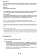
2.1.2 Introducing Audio Dynamics The human ear can detect the noise generated by falling leaves as well as the roar generated by the taking off space shuttle. Unfortunately no analog, nor digital device can reproduce such wide spectrum. Please look at Chart.1 and you will see the difference when dynamic capacity of various devices compare to the human ear. More problems occur when handling high level signals and low level signals.
2.1.4 More about noise: Expanders and Noise-Gates A lot of instruments such as microphones, amplifiers, guitar pickups, etc generate some noise, either at low frequencies (hum) or at high frequencies (hiss) such noise will inevitably interfere with the quality of your audio signal. Now, if you scream into a microphone you will not hear the noise generated by such microphone because such noise will be "masked" by the higher level of the signal, your voice in this case.
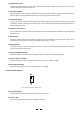
5. Threshold Control This control adjusts the threshold level for the Compressor section in the range of -40dBu to +20dBu. The SKC (Smart Knee Control) is applied to the audio signal, which is a maximum of 10dB above the set threshold. Above such level (10dB) a hard knee compression will be applied. 6. Threshold LED These LED's will show you the state of the input signal in relation to the threshold level. If the input signal falls below the set threshold level the left "-" LED will light up.
11. Output Gain Control Through this control you can vary the output signal by a maximum of 20dB. In this way you can recover the level lost during the compression process. 12. SC External Switch This switch will sever the connection between the audio input and the sidechain path. But at the same time it will also allow an external signal through the SC return jack present on the rear panel. 13.
3.4 Connectors on The Rear Panel 22 110-120V 220-240V 23 26 25 24 27 28 Pic. 5 The Rear Panel of The ACL2 PRO 22. Fuse holder / Voltage Selector This is a dual voltage unit. Before you attempt to connect and operate the unit, please make sure that your local voltage matches the voltage on the fuse-holder cover. Caution: The fuse protecting the AC supplies circuits of this unit. The fuse can only be changed by a qualified technician, in the event of a fault or changing the supply voltage.
27. Sidechain Send Through this 1/4" unbalanced jack the audio signal can be routed to an external processor. 28. Sidechain Return The return signal of an external processor will be processed through this 1/4" jack. 4. READY TO ROLL? 4.1 Expander/Gate Section Chart. 3 Function of an expander As we told you previously in this Manual the downward expander will reduce automatically the level of the audio signal when such signal is below a set threshold.
4.2.2 Ratio control This control sets the change of input level to output level but only for the signals that exceed the threshold. The scale of the ratio control on the front panel (calibrated in dB) indicates how much input level is required to increase the output level by 1 dB. If you have a ratio equal to 1:1 you will get the same level of input and output signal: So, no level change.
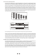
4.2.8 Gain Reduction Meter This consists of 12 LED on the front of the ACL2 PRO. Through this Led meter you can visualise the amount of gain reduction at any given time. Chart. 6 The effect of a compressor can be expressed as the amount of gain reduction that is taking place for any given input 4.3 Peak Limiter Section How fast is the compressor to react to a signal which is above the threshold point? This is determined by the attack time.
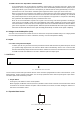
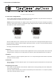
a. Wiring Configuration Both types of connectors available on ACL2 PRO can be wired in balanced and unbalanced modes. Please see following drawing for details: For 1/4" Phone jack For XLR connector XLR Type Unbalanced XLR Type Balanced b. In Line Connection Please see following drawing for details.
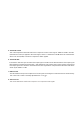
c. Insert Points Connection In case you are using the main inserts of your mixing console and you have a single jack for SEND and RETURN, you can use an insert Y cable. Please see following drawing.
6. TECHNICAL SPECIFICATIONS AUDIO INPUT Type Active balanced XLR and 1/4"JACK Impedance Balanced: 50K Ohm Unbalanced: 25K Ohm Operating Level Maximum input level AUDIO OUTPUT CMRR Type Balanced and Unbalanced: +21 dBu Impedance XLR and 1/4" JACK Balanced: 60 Ohm Unbalanced: 30Ohm Maximum output level Bandwidth +21 dBu 20Hz to 20KHz at +0,-0.5dB 0.01% typ.1KHz, @+4dBu THD +N% 0.04% typ,1KHz, @+20dBu SC RETURN SC SEND EXPANDER/GATE SECTION IMD 0.
INDICATORS GAIN REDUCTION: 12 element LED INPUT / OUTPUT LEVEL: 8 element LED EXPANDER/GATE THRESHOLD: 2 element LED ( under"+" above"-") COMPRESSOR THRESHOLD: 3 element LED ( under"+" smart "0" above"-" ) PEAK LIMITER THRESHOLD: 1 element LED (Limiter Function ) Function switch: LED indicator for each POWER SUPPLY 95-120V/ 210-240V, 60-50Hz FUSE: POWER CONSUMPTION 14 Watts DIMENSIONS 483(W) 194.5(D) 44(H)mm (19" 7.7" 1.7") WEIGHT 3.1kg(6.
7. WARRANTY 1. WARRANTY REGISTRATION CARD To obtain Warranty Service, the buyer should first fill out and return the enclosed Warranty Registration Card within 10 days of the Purchase Date. All the information presented in this Warranty Registration Card gives the manufacturer a better understanding of the sales status, so as to purport a more effective and efficient after-sales warranty service.
SEKAKU ELECTRON INDUSTRY (H.K.) CO. LTD. No.1, Lane 17, Sec. 2, Han Shi West Road, Taichung, 401 TAIWAN http://www.altoproaudio.com Tel:886-4-22313737 email: alto@altoproaudio.com Fax:886-4-22346757 All rights reserved to ALTO. All features and content might be changed without prior notice. Any photocopy, translation, or reproduction of part of this manual without written permission is forbidden. Copyright c 2004 Sekaku Electron NF01957-1.