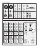
PM-6 DRAGONFLY User's Manual 6-CHANNEL MIXING CONSOLE WITH DIGITAL EFFECTS R LTO www.altoproaudio.com Version 1.
the recommended fuse type as indicated in this manual. Do not short-circuit the fuse holder. Before replacing the fuse, make sure that the product is OFF and disconnected from the AC outlet. SAFETY RELATED SYMBOLS CAUTION RISK OF ELECTRIC SHOCK DO NOT OPEN Protective Ground This symbol, wherever used, alerts you to the presence of un-insulated and dangerous voltages within the product enclosure. These are voltages that may be sufficient to constitute the risk of electric shock or death.
PREFACE Dear Customer: Thank you for choosing the LTO PM-6 DRAGONFLY 6-Channel Mixing Console with Digital Effects, which is the result of our LTO AUDIO TEAM's endeavours. For the LTO AUDIO TEAM, music and audio are more than a profession, it is a passion and an obsession! We have, in fact, been designing professional audio products for a number of years in cooperation with many of the world's major brands.
TABLE OF CONTENTS 1. INTRODUCTION...................................................................................................................................4 2. FEATURES............................................................................................................................................4 3. READY TO START................................................................................................................................4 4. CONTROL ELEMENTS...........................
1. INTRODUCTION Thank you very much for expressing your confidence in LTO products by purchasing PM-6 DRAGONFLY 6-Channel Mixing Console with Digital Effects. The PM-6 is a professional compact mixer, which Provides the state of the art digital amplifier technology specifically. You will get the smooth, accurate more natural and open sound from this apparatus, and it is really ideal for small gigs, recording and fixed PA installations.
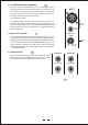
3.5 Possible System Connection Mode for Live Sound Application Passive Speakers Control Room Monitor L R MODEL LEFT TIP THIS CONNECTION FOR ALTO POWER SUPPLY ONLY! SERIAL DYNAMIC POWER: 2 80W @4 RIGHT L SLEEVE R CAUTION RISK OF ELECTRIC SHOCK DO NOT OPEN ATTENTION! MIN.
4.
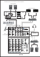
4.1 The MONO MIC/LINE CHANNELS 1 These are Channel 1 and Channel 2. You can connect a balanced, low impedance microphone to the XLR socket. ON the 1/4" phone jack you can connect either a microphone or a line level instrument. You shall never connect an unbalanced microphone to the XLR socket if you do not want to damage both the Microphone and the Mixer. MIC 1 2 1 3 18 Volt Phantom power It is available only to the XLR input sockets.
4.4 3-BAND EQUALIZER 3-band equaliser is provided for all input channels with a wide range of frequency adjustment. - HI 4 This is the treble control. You can use it to get rid of high frequency noises or to boost the sound of cymbals or the high harmonics of the human voice. The gain range goes from -15dB to +15dB with a center frequency of 12kHz. 0 -15 5 - MID This is the midrange control. It can affect most fundamental frequencies of all musical instruments and human voice.
4.9 MASTER SECTION 15 11 - MAIN MIX LEVEL This control sets the amount of signal simultaneously sent to the MAIN MIX OUTPUT and TAPE OUT. 18 14 17 0 PHANTOM POWER CLIP 12 +15 AUX RTN (DFX) 8 16 2TK TO MIX This stereo 6 segments LED Meter will indicate the signal level sent to CONTROL ROOM and PHONES outputs. MAX 2TK IN 8 13 - 2-TRACK signal path 13 -10 - - LED METER 0 -4 - 8 This control sets the amount of signal simultaneously sent to the CONTROL ROOM OUTPUT and PHONES.
- 24 BIT DIGITAL EFFECTS - PRESETS 15 14 13 12 11 19 19 Adjust this knob to select the right effect you wish to perform. There are total 16 options for you: Vibraflange, Funky, Rockabilly, Bigstage, Vibrato, Flanger and Chorus etc.
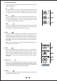
AUX SENDS STEREO AUX RETURNS CONTROL ROOM OUTPUT LTO LEFT PHONES R PM-6 LEFT 6-CHANNEL MIXING CONSOLE WITH DIGITAL EFFECTS RIGHT RIGHT 28 29 30 31 28 - STEREO AUX RETURNS Use these stereo 1/4" phone sockets to return the sound of an effect unit to the Main Mix. Alternatively you can use them as an extra auxiliary input. 29 - AUX SENDS This 1/4" phone socket is used to send out the signal from the AUX bus to external devices such as effects and sound processors.
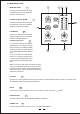
4.11 The Power Supply Box 37 36 35 ON DC OUTPUT OFF 34 POWER - POWER CORD AC INPUT 210-240V 50Hz POWER CONSUMPTION 130W 34 You can connect the plug of POWER CORD to the mains. Please check the voltage accepted by the unit and the voltage available from your AC sockets before connecting the unit to the mains. 35 - DC OUTPUT You can connect the cable from DC OUTPUT to POWER IN on rear panel. Thus, the power supply box will provide ±24V DC voltage to your mixing console.
5. INSTALLATION AND CONNECTION Ok, you have got to this point and you are now in the position to successfully operate your PM-6 DRAGONFLY. However, we advise you to read carefully the following section to be the real master of your own Mixer. Not paying enough attention to the input signal level, to the routing of the signal and the assignment of the signal will result in unwanted distortion, a corrupted signal or no sound at all. So you should follow these procedures for every single channel: 1).
5.1. Some Final Tips on Wiring Configuration You can connect unbalanced equipment to balanced inputs and outputs. Simply follow these schematics.
6. FOR THE EXPERTS WHO WANTS TO KNOW MORE As we have told you previously in this manual, the Aux Send Control both on mono and stereo channels is factory wired as POST-FADER. If you are skilled in electronic components soldering you can modify this setting and have all your AUX sends configured as PRE-FADER.
7. PRESET LIST Description parameter No. Preset 1 VibraFlange Slight pitch variation with Flanger effect. Mod Level : 90% 2 Funky Large pitch variation with heavy Flanger effect. Mod Level : 68% 3 Rockabilly Simulate a stage space with slight Flanger effect Rate : 0.1 Hz 4 Big stage Simulate a stage space of the sound. Decay time : 5.4s 5 Vibrato 4 Slight variation of pitch resulting from the free oscillation of the vocal cords. Rate : 4.
8.
9. TECHNICAL SPECIFICATION Mono input channels Microphone input electronically balanced, discrete input configuration Frequency response 10Hz to 55kHz, + Distortion (THD & N) 0.005% at +4dBu, 1kHz 0dB to 44dB (MIC) 3dB Gain range SNR (Signal to Noise Ratio) >100dB electronically balanced Line input Frequency response Distortion (THD & N) Sensitivity range Line input 10Hz to 55kHz, + 3dB 0.
10. WARRANTY 1. WARRANTY REGISTRATION CARD To obtain Warranty Service, the buyer should first fill out and return the enclosed Warranty Registration Card within 10 days of the Purchase Date. All the information presented in this Warranty Registration Card gives the manufacturer a better understanding of the sales status, so as to purport a more effective and efficient after-sales warranty service.
SEIKAKU TECHNICAL GROUP LIMITED SEKAKU ELECTRON INDUSTRY (H.K.) CO., LTD. No. 1, Lane 17, Sec. 2, Han Shi West Road, Taichung 40151, Taiwan http://www.altoproaudio.com Tel: 886-4-22313737 email: alto@altoproaudio.com Fax: 886-4-22346757 All rights reserved to ALTO. All features and content might be changed without prior notice. Any photocopy, translation, or reproduction of part of this manual without written permission is forbidden. Copyright c 2005 SEIKAKU GROUP NF02047-1.