User's Manual S 6 6 CHANNEL MIXING CONSOLE R LTO www.altoproaudio.com Version 2.0 Dec.
the recommended fuse type as indicated in this manual. Do not short-circuit the fuse holder. Before replacing the fuse, make sure that the product is OFF and disconnected from the AC outlet. SAFETY RELATED SYMBOLS CAUTION RISK OF ELECTRIC SHOCK DO NOT OPEN Protective Ground This symbol, wherever used, alerts you to the presence of un-insulated and dangerous voltages within the product enclosure. These are voltages that may be sufficient to constitute the risk of electric shock or death.
PREFACE Dear Customer: Thank you for choosing the endeavours. For the LTO S-6 6-Channel Mixing Console, which is the result of our LTO AUDIO TEAM's LTO AUDIO TEAM, music and audio is more than a profession, it is a passion and an obsession! We have, in fact, been designing professional audio products for a number of years in cooperation with many of the world's major brands. The LTO line represents unparalleled analogue and digital products made by musicians, for musicians.
TABLE OF CONTENTS 1. INTRODUCTION..................................................................................................................................4 2. FEATURES...........................................................................................................................................4 3. READY TO START?.............................................................................................................................4 4. CONTROL ELEMENTS...............................
1. INTRODUCTION Your S-6 is a 6-channel mixer and it is the smallest among our range of mixing consoles. Although, great performances and sound quality is insured thanks to the specification of the components used and the building quality.
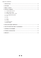
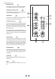
4. CONTROL ELEMENTS STEREO AUX RETURN MIC 2 MIC 1 AUX SENDS CONTROL ROOM OUTPUT LTO 2 1 2 3 1 3 LEFT(MONO) LEFT PHONES RIGHT BAL OR UNBAL BAL OR UNBAL LINE IN 1 LINE IN 2 TRIM TRIM S-6 R 6-CHANNEL MIXING CONSOLE RIGHT 2-TRACK IN/OUT MAIN MIX OUTPUT LINE IN 5/6 LINE IN 3/4 L LEFT (MONO) LEFT(MONO) LEFT R -45dB LINE 60dB MIC EQ EQ HI 12kHz HI 12kHz HI 12kHz HI 12kHz 0 +15 -15 0 +15 0 +15 MID 2.5kHz +12 -12 +12 +15 -15 -12 +15 -15 +12 MID 2.
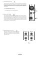
4.1 The MIC/LINE channels 1 These are Channel 1 and Channel 2. You can connect balanced, low impedance microphones to the XLR socket. ON the 1/4" phone jack you can connect either a microphone or a line level instrument. You shall never connect an unbalanced microphone to the XLR socket if you do not want to damage both the Microphone and the Mixer. MIC 1 2 1 3 4.1.1 PHANTOM POWER +48 Volts It is available only on the XLR input sockets. 1 BAL OR UNBAL 4.
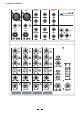
4.3 The 3 BANDS EQUALISER A 3-band equaliser is provided for all input channels with a wide range of frequency adjustment. EQ 4 4.4.1 HI This is the treble control. You can use it to get rid of high frequency noises or to boost the sound of cymbals or the high harmonics of the human voice. The gain range goes from -15dB to +15dB with a center frequency of 12 kHz. -15 -12 5 4.4.2 MID This is the midrange control.
4.9 MASTER section 11 - MAIN MIX LEVEL This Control sets the amount of signal sent either to the Main Out socket or to the Tape Output. 12 - PHONES/CONTROL ROOM This Control sets the amount of signal sent to the Control Room and headphone. 16 PHANTOM PWR 13 17 This stereo 6 segments Led Meter will indicate the level of the overall output signal.
19 - MAIN MIX OUTPUT This stereo output is controlled by the Main Mix Level on the front panel and will send the audio signal to an amplifier. The output level can be varied from - to +15dB.
4.10 REAR PANEL ON CAUTION RISK OF ELECTRIC SHOCK DO NOT OPEN MODEL WARNING: SHOCK HAZARD - DO NOT OPEN AVIS: RISQUE DE CHOC ELECTRIQUE - NE PAS OUVRIR SERIAL OFF POWER 18VAC~ RATED POWER CONSUMPTION: 11W 25 26 25 - POWER This switch is used to turn the Main Power ON and OFF. - 18VAC 26 Used to connect the supplied AC Adapter.
5. INSTALLATION AND CONNECTION Ok, you have got to this point you are now in the position to successfully operate your S-6. However, we advise you to read carefully the following section to be the real Master of your own Mix. Not paying attention enough to the Input signal level, to the routing of the signal and the assignment of the signal will result in unwanted distortion, a corrupted signal or no sound at all.
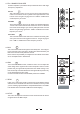
b. Some Final Tips on Wiring Configuration You can connect unbalanced equipment to balanced inputs and outputs. Simply follow these schematics.
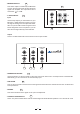
6. FOR THE EXPERTS WHO WANT TO KNOW MORE As we have told you previously in this Manual, the Aux Send Control both on Mono and stereo channels is factory wired as POST-FADER. If you have some skill in electronic components soldering you can modify this setting and have all your AUX sends configured as PRE-FADER.
14 A B C D 2 3 1 T R RN TN 5e S 3c 4d 2b 1a 1 RIGHT LEFT(MONO) T R RN TN T R RN TN 5e S 3c 4d 2b 1a 5e S 3c 4d 2b 1a STEREO AUX RETURN RIGHT LEFT(MONO) T R RN TN 5e S 3c 4d 2b 1a STEREO INPUT CHANNELS (3-6) LINE IN MIC IN PHANTOM POWER +48V 2 HI + - + - + 80 2.5K 12K EQ +/-15dB MID 80 2.5K 12K 3-BAND EQ LO MID 3 HI SG/OL SG/OL 3 +/-15db 80 2.
8. TECHNICAL SPECIFICATION Mono input channels Microphone input Frequency response Distortion (THD&N) Gain range SNR (Signal to Noise Ratio) Line input Frequency response Distortion (THD&N) Sensitivity range electronically balanced, discrete input configuration 10Hz to 55kHz, +/ 3dB 0.005% at + 4dBu, 1kHz 0dB to 60dB(MIC) 115dB electronically balanced 10Hz to 55kHz, +/ 3dB 0.005% at + 4dBu, 1kHz +15dBu to 45dBu Line input Frequency response Distortion (THD&N) balanced 10Hz to 55kHz, +/ 3dB 0.
9. WARRANTY 1. WARRANTY REGISTRATION CARD To obtain Warranty Service, the buyer should first fill out and return the enclosed Warranty Registration Card within 10 days of the Purchase Date. All the information presented in this Warranty Registration Card gives the manufacturer a better understanding of the sales status, so as to purport a more effective and efficient after-sales warranty service.
SEIKAKU TECHNICAL GROUP LIMITED No. 1, Lane 17, Sec. 2, Han Shi W. Road, Taichung, 401 Taiwan http://www.altomobile.com Tel: 886-4-22313737 email: info@altomobile.com Fax: 886-4-22346757 All rights reserved to ALTO Mobile. Due to continued development in response to customer feedback, product features, specifications and/or internal/external design may be changed without prior notice. No photocopying, translation or reproduction of any part of this user manual is allowed without prior written permission.