SCRUBTEC SCRUBTEC SCRUBTEC SCRUBTEC SCRUBTEC SCRUBTEC 770 770 784 784 795 795 S L S L S L Operator's Manual MODELS: 05210F, 05210G, 05211F, 05220F, 05220G, 05221F 05230F, 05231F U.S. Patent No. 6,760,947; No. 6,105,192; No. RE39,581 (Deluxe Machines) EN English (2-30) READ THIS MANUAL Parts List (31-67) Form No. 70935A 11/07, Revised 12/09 Printed in the U.S.A.
READ THIS BOOK This book has important information for the use and safe operation of this machine. Failure to read this book prior to operating or attempting any service or maintenance procedure to your Nilfisk ALTO machine could result in injury to you or to other personnel; damage to the machine or to other property could occur as well. You must have training in the operation of this machine before using it.
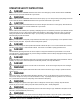
OPERATOR SAFETY INSTRUCTIONS DANGER! Failure to read and observe all DANGER statements could result in severe bodily injury or death. Read and observe all DANGER statements found in your Owner’s Manual and on your machine. WARNING! Failure to read and observe all WARNING statements could result in injury to you or to other personnel; property damage could occur as well. Read and observe all WARNING statements found in your Owner’s Manual and on your machine.
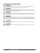
OPERATOR SAFETY INSTRUCTIONS WARNING! Electrical components of this machine can “short-out” if exposed to water or moisture. Keep the electrical components of the machine dry. Wipe the machine down after each use. For storage, keep the machine in a dry building. WARNING! Operating a machine without observing all labels and instructional information could result in injury or damage. Read all machine labels before attempting to operate.
INTRODUCTION Nilfisk ALTO’s newly designed Scrubtec 795, 784 & 770 automatic scrubbers are efficient and superior floor cleaning machines. The Scrubtec 795 uses two brushes or pads to scrub a path 97 cm wide. The Scrubtec 784 uses two brushes or pads to scrub a path 84 cm wide. The Scrubtec 770 uses two brushes or pads to scrub a path 71 cm wide. A squeegee wipes the floor while the vacuum motor removes the dirty solution from the floor - all in one pass.
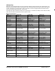
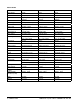
SPECIFICATIONS: Model Scrubtec 795L Scrubtec 784L Scrubtec 770L Model Number 05231F 05221F 05211F Motor, Vac 1 HP (.74kw) three 1HP (.74kw) three 1HP (.
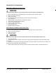
PROCEDURES FOR TRANSPORTING How To Put The Machine In A Van Or Truck WARNING: The machine is heavy. Make sure you use two able persons to assist the machine in climbing the ramp. 1. 2. 3. 4. 5. 6. 7. 8. 9. 10. 11. Make sure the loading ramp is at least eight (8) feet long, and strong enough to support the machine. Make sure the ramp is clean and dry. Put the ramp in position. Remove squeegee assembly, brush housings, & brushes or pad drivers before loading. Turn key switch “ON”.
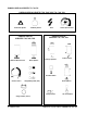
SYMBOLS USED ON SCRUBTEC 770, 784, 795 SYMBOLS USED ON SCRUBTEC 770S, 784S, 795S / 770L, 784L, 795L On/Off Key Switch Hazard Alert Symbol SYMBOLS USED ON SCRUBTEC 770S, 784S, 795S Additional Brush Pressure Brush Up/Down Power Traverse Speed Control SYMBOLS USED ON SCRUBTEC 770L, 784L, 795L Squeegee Up/Down Solution Control Hour Meter Switch Solution Control Brush Up/Down Charge/Battery Meter (Solo) Charge Indicator One Touch Switch Charge Indicator (I-Drive) -8- FORM NO.
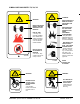
SYMBOLS USED ON SCRUBTEC 770, 784, 795 WARNING WARNING READ OPERATOR'S MANUAL BEFORE OPERATING THIS MACHINE READ OPERATOR'S MANUAL BEFORE OPERATING THIS MACHINE EXPLOSIVE GASES, CAN CAUSE SEVERE INJURY, DEATH OR DAMAGE TRANSFORMER. • Keep flammable materials away from batteries. Charge in a cool well ventilated RISK OF FIRE • Use only commercially available floor cleaners and waxes intended for machine operation. • Do not use flammable materials. 71018A BATTERIES CONTAIN SULFURIC ACID.
MACHINE CONTROL PANEL 770S, 784S & 795S Key Switch (See Figure #1, Item “A”) The key switch turns “ON” the power to the control panel. “0” is “OFF” and “I” is “ON”. Traverse Speed Switch (See Figure #1, Item “B”) The speed control varies from low to high speed. To increase the speed, turn the knob to the right. To decrease the speed, turn the knob to the left.
MACHINE CONTROL PANEL 770S, 784S & 795S Figure #1 B G F E M L F C K D J I A H1 N H2 Nilfisk ALTO Operator's Manual - SCRUBTEC 770 / 784 / 795 FORM NO.
MACHINE CONTROL PANEL 770L, 784L & 795L Key Switch (See Figure #2 Item “A”) The key switch turns “ON” the power to the control panel. “O” is “OFF” and “I” is “ON”. Traverse Speed Switch (See Figure #2, Item “B”) The speed control varies from low to high speed. To increase the speed, turn the knob to the right. To decrease the speed, turn the knob to the left. Squeegee Up/Down Switch (See Figure #2, Item “C”) The squeegee switch is used to raise and lower the squeegee and to turn on and off the vacuum motor.
MACHINE CONTROL PANEL 770L, 784L & 795L Figure #2 G F B F E D C M I A L K Nilfisk ALTO Operator's Manual - SCRUBTEC 770 / 784 / 795 J H FORM NO.
DISPLAY SCREENS FOR SCRUBTEC 770L, 784L, 795L Position arrow indicating current position of squeegee (up or down) 3 Indicators are on all the time showing current settings. SCREEN 1 Water “droplets” off when solution is off and they are flashing when solution is on. “Battery” blinks when low voltage occurs. Screens Available to Operator Arrows indicating vacuum status. They are flashing when vac is on and off when vac is off. SCREEN 2 Example SCREEN 3 (Diagnostic) The Diagnostic only.
EN MACHINE CONTROLS & FEATURES Squeegee Lift Handle (“S Class” models only) See Figure #3a, 3b, & 3c. The squeegee lift handle is located below the control handles on the right side. It is used to raise or lower the squeegee. The vac motor is turned on when the handle is lowered. Parking Brake (Optional)See Figure #4. The parking brake prevents movement of the machine. The brake is located on the left hand side of the transaxle motor.
HOW TO PREPARE THE MACHINE FOR OPERATION How To Install The Batteries 38722B 1. Turn key switch off. 2. Make sure both tanks are empty. 3. Disconnect the hoses from the recovery tank (upper tank) & unplug the vac motor and float switch. 4. Remove the tank support bracket. 5. Remove the recovery tank. 6. Place the batteries in the solution tank as shown in figures 6a and 6b. 38720B To Install the batteries, follow this procedure: 38720B The Scrubtec machines use six 6-volt batteries.
HOW TO PREPARE THE MACHINE FOR OPERATION Battery Maintenance The electrical power to operate the machine comes from the storage batteries. Storage batteries need preventive maintenance. WARNING! Correct fill level Working with batteries can be dangerous. Always wear eye protection and protective clothing when working near batteries. NO SMOKING! To maintain the batteries in good condition, follow these instructions: 1. Keep the electrolyte at the correct level.
HOW TO PREPARE THE MACHINE FOR OPERATION How To Charge The Batteries WARNING! Charging the batteries in an area without adequate ventilation could result in an explosion. To prevent an explosion, charge the batteries only in an area with good ventilation. WARNING! Lead acid batteries generate gases which could explode. Keep sparks and flames away from batteries. NO SMOKING! To charge the batteries, follow this procedure: 1. Make sure the key switch is in the “OFF” position. 2.
HOW TO PREPARE THE MACHINE FOR OPERATION How To Install The Brushes Or Pad Drivers To install the brushes or pad drivers on the machine, follow this procedure: 1. Turn the key switch “ON”. 2. Put the brush switch in the “UP” position. 3. Turn the key switch “OFF”. 4. Go to the front of the machine. 5. Unlatch right and left brush housings and remove them. See figure #9. 6. Put a brush or pad driver under the brush motor plate. See figure #10. 7.
HOW TO OPERATE THE MACHINE How to Operate the One Touch System (“L Class” models only) One touch cleaning is a feature on the new Scrubtec Walk-behind Scrubber. The factory defaults for this setting are two bars of brush pressure and four bars for solution flow and squeegee in the down position. 1. Press and release the green button for all cleaning functions to begin, see figure #11, item A. 2. The squeegee and brush head lower to the floor and the vacuum starts.
HOW TO OPERATE THE MACHINE How To Operate the Squeegee (“S Class” models only) The squeegee wipes the floor while the vacuum motor removes the dirty solution from the floor. Use your right hand to lower or raise the squeegee handle. To operate the squeegee, follow this procedure: 1. To lower the squeegee and start the vac motor move the squeegee lever to the right and down. See figure #12. 2. To raise the squeegee, lift the squeegee lever up. See figure #13.
HOW TO OPERATE THE MACHINE How To Traverse Machine NOTE: Put the machine in the slow traverse speed (see figure #17). Use the machine in an area that has no furniture and objects until you can do the following: 1. Move the machine in a straight direction, forward and backward. 2. Stop the machine safely. 3. Move the machine in a straight direction after you turn the machine. To move the machine, follow this procedure: 1. Turn the key switch “ON” position. 2.
HOW TO OPERATE THE MACHINE How to Clean a Very Dirty Floor To clean a very dirty floor, follow this procedure: 1. Apply solution to the floor. 2. Do not lower the squeegee. 3. Do not activate the vacuum motor. 4. Lower the brushes and scrub the floor. 5. Leave the solution on the floor long enough for the solution to begin cleaning the floor. 6.
MAINTENANCE Do These Procedures When You End Your Work 1. Drain the solution tank (Figure #21, item A) and the recovery tank (Figure #21, item B). To drain the tanks , follow this procedure: a. Turn the key switch “OFF”. b. Remove the drain hose from the back of the machine. c. Put the end of the hose over a drain or bucket. d. Recovery Tank: Turn the valve housing to the left (see figure #22). To open the valve completely, turn the housing fully to the left and pull the housing off of the valve.
MAINTENANCE These Maintenance Procedures Must Be Done Every Week: WARNING! Maintenance and repairs must be done by authorized personnel only. Always empty the solution tank and the recovery tank before doing any maintenance. Keep all fasteners tight. WARNING! Always wear eye protection and protective clothing when working near batteries. Do not put tools or other metal objects across the battery terminals or the tops of the batteries.
MAINTENANCE 7. Check the squeegee and the scrub brushes or the pad drivers for damage. 8. Check the squeegee and the vacuum hose for damage, leaks and obstructions. Maintenance For The Squeegee To remove the squeegee, follow this procedure: 1. Remove the squeegee assembly by loosening the two knobs that attach the squeegee to the machine. Pull the squeegee assembly off. See figure #26. 2. Inspect the squeegee blade. 3.
MAINTENANCE Adjusting Squeegee Blades When properly installed the front blade should be approximately .12 above the rear blade. See figure #29. WARNING! Maintenance and repairs must be done by authorized personnel only. WARNING! Electrical repairs must be done by authorized personnel only. 0.12" (3.0 mm) Consult your Nilfisk Alto Authorized Service Person to do the service procedures. Figure #29 Use only genuine Nilfisk Alto parts.
HOW TO CORRECT PROBLEMS IN THE MACHINE PROBLEM The machine does not remove all the water from the floor. CAUSE The squeegee is up ACTION Lower the squeegee. The vacuum tank is full. Drain the tank. The screen filter is dirty. Clean the screen filter. There is an obstruction or damage in the squeegee, squeegee hose or standpipe. The vacuum motor is not running. Remove the obstruction or repair the damage. Check for tripped breaker. Have an authorized service person make repairs. Connect the hose.
SCRUBTEC 770L / 784L / 795L WB Common Error Codes ERROR CODE 3100 3101 3102 3103 3104 3105 7600 7603 7800 7802 9000 2F01 CAUSE Probable short circuit of output device. ACTION Check the traction, brush and vac motor connections on the trio and check wiring from these connectors down to the traction, brush and vac motors. Open circuit on brush motors or brush motor wiring. Possible short circuit on brush motors or wiring. Open circuit on traction motor.
-30- FORM NO.
SCRUBTEC SCRUBTEC SCRUBTEC SCRUBTEC SCRUBTEC SCRUBTEC 770 770 784 784 795 795 S L S L S L Section II Parts and Service Manual (70935A) U.S. Patent No. 6,760,947; No. 6,105,192; No. RE39, 581 (Deluxe Machines) Nilfisk ALTO Operator's Manual - SCRUBTEC 770 / 784 / 795 FORM NO.
Nilfisk ALTO SCRUBTEC 770 / 784 / 795 Solution Tank Assembly 12/09 1 2 3 35 33 36 34 4 37 40 38 5 6 39 7 46 8 41 43 30 9 10 42 44 11 12 12 32 31 30 29 14 31 19 17 18 21 45 24 21 -32- FORM NO.
Nilfisk ALTO SCRUBTEC 770 / 784 / 795 Solution Tank Assembly 12/09 Item 1 2 3 4 5 6 7 8 9 10 11 12 13 14 15 16 17 18 19 20 21 22 23 24 25 26 27 28 29 30 31 32 33 34 35 36 37 38 39 40 41 42 43 44 45 46 47 Ref. No.
Nilfisk ALTO SCRUBTEC 770 / 784 / 795 Recovery Tank Assembly 12/09 1 2 5 3 7 37 6 3 38 8 4 9 39 14 10 11 15 36 22 35 23 26 34 27 22 28 33 17 13 9 24 18 16 20 21 32 20 20 12 11 19 29 25 31 30 -34- FORM NO.
Nilfisk ALTO SCRUBTEC 770 / 784 / 795 Recovery Tank Assembly 12/09 Item Ref. No.
Nilfisk ALTO SCRUBTEC 770 S / 784 S / 795 S Electrical Panel Assembly / Solo Speed Controller 12/09 39 27 28 5 37 18 20 5 35 6 15 5 17 31 25 52 51 50 13 12 14 7 30 11 10 18 24 45 46 5 5 18 44 49 53 32 54 48 21 16 43 47 34 33 29 40 42 38 54 36 26 41 4 9 5 19 20 1 55 23 6 5 22 3 5 2 8 7 3 -36- FORM NO.
Nilfisk ALTO SCRUBTEC 770 S / 784 S / 795 S Electrical Panel Assembly / Solo Speed Controller 12/09 Item Ref. No.
Nilfisk ALTO SCRUBTEC 770 S / 784 S / 795 S Electrical Panel Assembly / I-Drive Speed Controller 12/09 -38- FORM NO.
Nilfisk ALTO SCRUBTEC 770 S / 784 S / 795 S Electrical Panel Assembly / I-Drive Speed Controller 12/09 Item Ref. No.
Nilfisk ALTO SCRUBTEC 770 L / 784 L / 795 L Electrical Panel Assembly Drawing 2/07 Drawing # 10855E 29 30 21 18 5 10 5 20 32 31 13 33 5 12 18 27 31 35 34 17 5 26 7 15 14 5 6 20 25 16 9 2 5 1 11 6 19 37 3 24 23 22 8 7 28 4 -40- FORM NO.
Nilfisk ALTO SCRUBTEC 770 L / 784 L / 795 L Electrical Panel Assembly Parts List 2/07 Drawing # 10855E Item Ref. No.
Nilfisk ALTO SCRUBTEC 770L / 784L / 795L Control Panel Assembly 12/09 7 7 12 6 9 8 4 13 3 15 16 10 5 1 2 3 20 23 17 19 22 21 18A 18B 24 32 25 29 28 31 26 30 27 30 Item Ref. No. Qty 1 2 3 4 5 6 7 8 9 10 12 13 15 16 17 18A 18B 19 20 21 22 23 30592A 85815A 980205 85813A 920110 52556A 40750A 50962A 962262 11131A 50961A 80104A 980608 962330 *see table 40883A 40786A 40748A 40880A 40758A 40168B 40747A 1 2 6 4 4 1 1 1 2 2 4 4 4 4 1 1 1 1 1 1 2 1 -42- FORM NO.
Nilfisk ALTO SCRUBTEC 770S / 784S / 795S Control Panel Assembly / Solo Speed Controller 12/09 Item Ref. No.
Nilfisk ALTO SCRUBTEC 770S / 784S / 795S Control Panel Assembly / I-Drive Speed Controller 12/09 -44- FORM NO.
Nilfisk ALTO SCRUBTEC 770S / 784S / 795S Control Panel Assembly / I-Drive Speed Controller 12/09 Item Ref. No.
Nilfisk ALTO SCRUBTEC 770 / 784 / 795 Squeegee Swing Arm Assembly 12/09 -46- FORM NO.
Nilfisk ALTO SCRUBTEC 770 / 784 / 795 Squeegee Swing Arm Assembly 12/09 Item Ref. No.
Nilfisk ALTO SCRUBTEC 770 / 784 Squeegee Assembly 12/09 -48- FORM NO.
Nilfisk ALTO SCRUBTEC 770 / 784 Squeegee Assembly 12/09 Item Ref. No. Qty 1 2 3 4 5 6 7 8 [] 9 10 11 12 13 14 [] 15 16 17 18 19 20 21 10803KL 25201B 34260B 81301A 30048A 53185A 60272B 30058A 30069L 30557A 80280A 80011A 60252A 930086 50835A 30717L1 30091A 60254A 30049B 81104A 60243A 60358A 980657 962720 2 1 2 2 2 1 1 1 1 2 2 1 2 1 1 1 2 4 2 2 2 4 4 Description Squeegee Asm. Knob Squeegee Gasket Nut, 3/8-16 Jam SS Wheel, Gide 4” Diam. Ring, 3/8 ID Snap Channel, Sq.
Nilfisk ALTO SCRUBTEC 795 Squeegee Assembly 12/09 -50- FORM NO.
Nilfisk ALTO SCRUBTEC 795 Squeegee Assembly 12/09 Item Ref. No.
Nilfisk ALTO SCRUBTEC 770 / 784 / 795 Traverse System Assembly 2/05 18 24 25 26 27 16 8 23 10 9 7 6 5 15 7 23 4 19 28 19 14 20 3 3 29 2 1 30 11 21 30 32 13 31 13 12 -52- FORM NO.
Nilfisk ALTO SCRUBTEC 770 / 784 / 795 Traverse System Assembly 2/05 Item Ref. No. Qty 1 2 3 4 5 6 7 8 9 10 11 12 13 14 18 19 20 21 23 24 25 26 27 28 29 30 31 32 66531A 836711 81104A 69877A 85811A 57275A 87623A 86004A 962288 85700A 920110 899769 81105A 59116A 59116E 85730A 59969A 30039A 59955A 81221A 980614 61594A 65963A 87625A 80011A 81207A 170883 58419A 980205 69639A 980645 962244 980638 1 1 2 1 2 1 2 1 6 1 2 2 12 1 1 4 2 1 2 6 3 1 2 2 2 2 2 2 2 1 6 4 4 Swing Arm Pin Hair Pin Nut, .
Nilfisk ALTO SCRUBTEC 770 / 784 / 795 Brush Head Assembly Drawing 2/05 1 2 3 4 5 55 6 8 1 9 7 2 10 11 54 12 49 50 51 49 47 48 13 53 20 14 15 16 17 46 18 19 13 45 52 44 43 27 42 40 39 41 38 37 20 21 30 22 29 28 23 36 31 27 26 25 24 32 35 17 34 -54- FORM NO.
Nilfisk ALTO SCRUBTEC 770 / 784 / 795 Brush Head Assembly Parts List 11/07 Item 1 2 3 4 [] [] 5 6 7 8 9 10 11 12 13 14 15 16 17 18 19 20 21 22 23 24 25 26 27 28 29 30 31 32 33 34 Ref. No.
Nilfisk ALTO SCRUBTEC 770 / 784 / 795 Brush Motor #45036A 2/05 13 7 12 12 1 13 2 Seam Location 3 14 16 4 15 5 Rotation 6 17 8 9 10 11 Item Ref. No. Qty 1 2 3 4 5 46734A 40318A 902654 902550 51840A 1 1 1 1 1 6 7 8 9 10 11 12 13 14 15 16 17 50520A 56480A 962546 50517A 448396 40826A 55657A 55656A 59805A 50515A 80501A 54238A 1 2 2 1 4 4 1 1 1 2 1 1 -56- FORM NO. 70935A Description Stator Assembly (w/Magnets & Clips) Armature Asm.(w/B.E. & F.E. bearings) Bearings B.E. Bearing F.E.
Nilfisk ALTO SCRUBTEC 770 / 784 / 795 Gear Box #54238A 2/05 9 8 7 6 5 4 3 2 1 Item Ref. No. Qty Description 1 2 3 4 5 6 7 8 9 NI 57846A 507641 52050A 56668A 51176A 58316A 902605 54883A 58144A 1 1 1 1 1 1 1 1 1 4oz. Ring, Snap Seal, Oil, Small Cap End O’Ring Bearing, Large Shaft & Gear, Gearbox Bearing, Small Housing Seal, Oil Large Darina Grease Nilfisk ALTO Operator's Manual - SCRUBTEC 770 / 784 / 795 FORM NO.
-58- FORM NO. 70935A 3 1 2 4 17 5 7 8 6 To replace coupler remove these two screws (Black) to separate the motor from gearbox to allow access to coupler 9 10 Model RPM Volt AMP. Duty Date 4 11 4BC-2800 1200 Ins. Cl. 36 VDC Mount 15 Shaft Cont Ser. No. 16:1 Ratio 12 1 2 3 4 Ref # HP .50 F Flange Tang PERMANENT MAGNET MOTOR MFG.
Nilfisk ALTO SCRUBTEC 770 / 784 / 795 Imperial Transaxle Parts 2/05 PN 59116A Item Ref. No.
ACCESSORIES Description Power Wand System Kit Soft Caster Asm. Drive Wheel, Foam Filled Imperial Electric Parking Brake Kit Clarke Battery Maintenance System (CBMS) Chemical Mixing System Chemical Mixing System Spare Tank Part No. 10892A 52127A 59955A 10684B 53390A 11081A 11037A OPTIONAL SQUEEGEE BLADES Machine 28, 33 28, 33 28, 33 28, 33 38 38 38 38 38 Part No.
Nilfisk ALTO SCRUBTEC 770 S / 784 S / 795 S Electrical Schematic (Solo Controller) 9/05 Nilfisk ALTO Operator's Manual - SCRUBTEC 770 / 784 / 795 FORM NO.
Nilfisk ALTO SCRUBTEC 770 S / 784 S / 795 S Electrical Schematic (I-Drive Controller) 12/09 -62- FORM NO.
Nilfisk ALTO SCRUBTEC 770 L / 784 L / 795 L Electrical Schematic 9/05 Nilfisk ALTO Operator's Manual - SCRUBTEC 770 / 784 / 795 FORM NO.
Overenstemmelseserklaering Declaration of conformity Konformitätserklärung Declaración de conformidad Atbilstības deklarācija Megfelelősségi nyilatkozat Certifikat o ustreznosti Declaration de conformité Verklaring van overeenstemming Dichiarazione di conformità Vastavussertifikaat Deklaracja zgodności Försäkran om överensstämmelse Samsvarserklaering Vaatimustenmukaisuusvakuutus Atitikties deklaracija Osvědčení o shodě Certifikát súladu Modell/ Modèle/ Model/ Malli/ Modelo/ Μοντέλο/ Modelo/ Modelis/Модел
Nilfisk ALTO LIMITED U.S. WARRANTY This Nilfisk ALTO Industrial/Commercial Product is warranted to be free from defects in materials and workmanship under normal use and service, when operated and maintained in accordance with Nilfisk ALTO's Maintenance and Operations instructions. The warranty period is subject to the conditions stated below.
Division of Nilfisk-Advance A/S Industrivej 1 9560 Hadsund Denmark Tel.: (+45) 72 18 21 00 Fax: (+45) 72 18 21 11 E-mail: salg@nilfisk-alto.dk E-mail: service@nilfisk-alto.dk www.nilfisk-alto.