
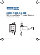
Instruction Manual


■
06
■ ■
07
■
Mounting the Receiver
1. Select a location within 6” adjacent to your sprinkler timer (receiver may
be located indoor or outdoor).
2. Mount rain/freeze receiver (antenna side up) using screws provided.
3. Extend and straighten the antenna upward.
Wiring the Receiver to Timer
Important: This sensor is designed for 24-Volt irrigation timers only. Do not
connect the receiver to 120/240 VAC. All wiring must conform to applicable local
codes. Disconnect power to the sprinkler timer (unplug timer, turn off the
appropriate circuit breaker or remove fuse) before attempting to connect the rain
sensor receiver.
The two most common wiring situations are detailed below. The green “normal
open” wire is not used in most installations. For nonstandard wiring situations,
please contact our customer support hotline at 1-888-HYDRORAIN.
24-Volt Solenoid Valves Only (No Booster Pump)
1. Remove wire terminal cover from timer.
2. Check your timer for pre-installed sensor terminals. If the timer does not
have sensor terminals, proceed to step 3. If it does, take the wire from rain/
freeze receiver and connect the white (common) wire to one sensor terminal
and the yellow (normal closed) wire to the other. (See Figure 3) Skip to step 5.
Section 2: INSTALLATION INSTRUCTIONS
3. Disconnect the common valve wire from the timer, and attach it (using
a wire nut) to the yellow (normal closed) wire from the rain/freeze receiver.
(See Figure 4)
4. Connect the white (common) wire from the rain/freeze receiver to the
common terminal of the timer.
5. Connect the (2) red “24V” wires to the 24V terminals of the timer.
24-Volt Solenoid Valves with Booster Pump
Note: The pump circuit output must be 24 volts in this situation—
if different, do not proceed.
1. Remove wire terminal cover from timer.
2. Check your timer for pre-installed sensor terminals. If the timer does not
have sensor terminals, proceed to step 3. If it does, take the wire from the rain/
freeze receiver and connect the white (common) wire to one sensor terminal
and the yellow (normal closed) wire to the other. (See Figure 3) Skip to step 5.
3. Disconnect the common valve wire(s) from the timer and the common wire
lead of the relay that starts the pump from the common terminal of the timer.
Attach them to the yellow (normal closed) wire from the receiver, using a wire
nut. (See Figure 5).
4. Connect the white (common) wire from the rain/freeze receiver to the
common terminal on the timer.
5. Connect the (2) red “24V” wires to the 24V terminals of the timer.
Section 2: INSTALLATION INSTRUCTIONS
08HYD005598 04008-24 rA.indd 7 11/16/07 3:39:36 PM