Orion 2000 Cable Router User’s Guide Rev. 1.2c Firmware 2.59.
Contents 1. BEFORE YOU BEGIN ...........................................................................................................5 Understand the Cable Modem’s Features ....................................................................................................... 5 Contact Your Local Cable Operator ................................................................................................................ 5 Prepare Your Area for Cable Modem Installation...................................
Image ................................................................................................................................................................ 35 Ping ................................................................................................................................................................... 35 Tracert ..............................................................................................................................................................
Reset.................................................................................................................................................................. 58 Quit ................................................................................................................................................................... 58 6. MODE OF OPERATION .....................................................................................................59 Bridge mode ...............................
1. Before You Begin Your new cable modem provides high-speed access to the Internet by an active Internet Connection through your cable service provider. This user guide describes how to set up and use the cable modem. Before installing the cable modem, you should read this user guide to ensure proper cable modem operation.
Prepare Your Area for Cable Modem Installation Before installing your cable modem, you should first prepare your area. To do this: 1. Locate your cable outlet and ensure that it is located within proper distance of your cable modem and computer. Be sure not to bend the cable as this may strain the connector and cause damage. 2.
Be sure to follow the instructions provided for the port that you want to use. Using the USB port allows you to install the cable modem more quickly and easily than using the Ethernet port, because you do not have to install and configure a network interface card (NIC). USB, however, only enables you to connect one computer to the cable modem. Using the Ethernet port allows you connect multiple computers to a cable modem through the use of additional equipment that is not included.
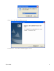
3. You will see the following Welcome screen. 4. Click “Next>”. You will see the following Start screen.
5. Click “Next>”. You will see the following ‘Complete’ screen. 6. Click “Finish”. You will see below screen, and then select ‘Yes.
USB cable to the PC by following next section instructions. Installing the Hardware This section explains how to connect the cable modem to the computer, wall outlet, and electrical outlet. To install the hardware: 1. Power off the computer 2. Connect one end of the coaxial cable to the cable modem’s cable connector. Connect the other end of the coaxial cable to the cable wall outlet. Be sure not to bend or over tighten the cables as this may strain the connector and cause damage.
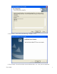
2. Insert the CD into the PC’s CD-ROM and click Next. You will see the following screen. 3. Select Search for the best driver for your device (Recommended). Then select Next. You will see the following screen.
4. Check the CD-ROM drive check box and verify that the CD is in the CD-ROM drive. Click Next to have Windows search for the necessary driver files. You will see the following: 5. Select the updated driver (Recommended) Ambit USB Cable Modem and click next. You will see the following screen.
CAUTION: You must verify that Ambit USB Cable Modem appears on the screen. If USB Composite Device appears, you must click Back twice and specify the correct location of the driver files. DO NOT proceed if USB Composite Device is displayed in the above window. Contact your cable provider for further assistance. 6. Click Next. The computer automatically installs the necessary driver files.
7. If the above screen appears, you must insert the Windows 98 CD so that Windows can copy the remaining files. 8. After files copying is done, you will see the following screen: 9. Click Finish to complete the installation. You will see the following screen.
10. Choose Yes to restart your computer. 11. After the computer is rebooted, verify that the USB LED is lit on the front of you cable modem. If not, refer to the troubleshooting section later in this chapter.
Installing the Software Drivers in Windows Me Operating System To install the cable modem software drivers using the Windows Me operating system: 1. Power on your PC. After your computer boots, Windows detects the cable modem. The Found New Hardware screen appears, followed by the Found New Hardware Wizard screen. 2. Insert the CD into the PC’s CD-ROM and click Next. You will see the following screen. 3. Select Automatic search for a better driver (Recommended) and click (Next).
4. Click Next. The computer automatically installs the necessary driver files. 5. Click Finish after the computer has copied the necessary files. You will see the following screen.
6.
Installing the Software Drivers in Windows 2000 Operating System To install the cable modem software drivers using the Windows 2000 operating system: 1. Power on your PC. After your computer boots, Windows detects the cable modem. The Found New Hardware screen appears, followed by the Found New Hardware Wizard screen. 2. Insert the CD into the PC’s CD-ROM Drive and click Next. You will see the following screen.
3. Select Search for a suitable driver for my device (recommended. Then select Next. You will see the following screen 4. Check the CD-ROM drive check box and verify that the CD is in the CD-ROM drive.
Next to have Windows locate the necessary driver files. You will see the following screen. 5. Click Next to install the driver files for the cable modem. You will see the following screen.
7. Click Finish to complete the installation. 8. After the installation is completed, verify that the USB LED is lit on the front of you cable modem. If not, refer to the troubleshooting section later in this chapter.
Installing the Software Drivers in Windows XP Operating System 1. Power on your PC. After your computer boots, Windows detects the cable modem. The Found New Hardware screen appears, followed by the Found New Hardware Wizard screen. 2. Choose the software automatically (Recommended). Click Next to continue. You will see the following screen.
3. Click Finish to complete the installation.
Troubleshooting the USB Installation None of the LEDs is on when I power on the LAN Cable Modem. Check the connection between the power adapter and the cable modem. Power off the LAN Cable Modem and wait for 5 Seconds and power on the modem again. If the problem still exists, you may have a hardware problem. When attempting to install the USB driver in Windows 98 SE, I receive the following error message: Device not installed at this time. Driver not found.
4. Select USB Composite Device and click Remove 5. Click Refresh The Add New Hardware Wizard window appears, displaying the device name USB Composite Device. Refer to the proper operating system instructions in this chapter for information on reinstalling the driver properly. All of the LEDs on the front of my modem look correct, but I cannot access the Internet. • If the POWER, USB, SYNC, and READY are solidly lit, the cable modem is working properly.
necessary files from you computer. 3. Installing the Modem Using the Ethernet Port This chapter explains the process for installing your cable modem using the Ethernet port. Using the Ethernet port allows to you connect multiple computers to a cable modem using additional equipment which is not included. Please contact your cable service provider for more information on using multiple computers.
4. Plug the cable modem’s power adapter into the cable modem’s power jack and into a wall outlet or surge protector. 5. If the POWER, ENET, SYNC, and READY LEDs are solidly lit, the cable modem is working properly. Troubleshooting the Ethernet Installation None of the LEDs are on when I power on the Cable Modem. Check the connection between the power adapter and the cable modem. Power off the Cable Modem and wait for 5 seconds and power on the modem again.
communications with your cable service provider. • If your PC is connected to a hub or gateway, try connecting the PC directly into the cable modem. • If you are using a cable splitter, try removing the splitter and connect the cable modem directly to the cable wall outlet. Wait several minutes for the cable modem to re-establish communications with your cable service provider. • • Your Ethernet or coaxial cable may be damaged. Try using another cable.
4. Cable Modem LEDs and Connectors This chapter describes the functions of the cable modem’s LEDs and connectors. When the PWR, SYNC, and READY LEDs are lit, the cable modem is working properly. The USB or ENET LED should also be lit depending on what port is being used. The following provides an overview of the LED indicator lights on the front of the cable modem and what the LEDs mean.
areas. Connectors on the Back of the Modem This list of connectors describes where to connect the cables and power adapter when installing the cable modem. 1. power: This is where you plug the include power adapter. Remember to use only the power adapter that came with the cable modem. 2. usb: This is where you plug the included USB cable. The other end connects to the USB port on your PC. It is not required when using the Ethernet port. 3. enet: This is where you plug the included Ethernet cable.
5. Telnet commands The Cable Router telnet Login and Password: Login: Password: ** Note: Cable Modem Router Telnet IP address is 192.168.100.1 Getting Help Entering a question mark (?) at the system prompt displays a list of commands for each command mode. To list keywords or arguments, enter a question mark (?) in place of a keyword or argument. Include a space before the ?.
line write reset quit Configure a terminal line Write configuratoin to nvram Reboot Cable Modem Disconnect To list keywords or arguments, enter a question mark (?) in place of a keyword or argument. Include a space before the ?. This form of help is called command syntax help, because it reminds you which keywords or arguments are applicable based on the command, keywords, and arguments you already have entered.
Debug ¾ debug Display corresponding message, the protocol debug just show packet information send to or receive from RF interface. CM>debug ? console ip dhcp arp l2 nat Display console message IP information DHCP protocol information ARP information Layer 2 information NAT translation information CM>debug ip ? tcp TCP information udp UDP information icmp ICMP information rip RIP protocol information Example: CM>debug ip tcp TCP: rcvd src:10.0.0.3(1150) dst:172.17.100.
all Disable all debugging functions Image ¾ image upgrade {1|2} Download the specified firmware image name from TFTP server and store in as “image 1” or “image 2”. If {1|2} is not specified, cable modem will upgrade the other image. (If cable modem boot with image 2, it will upgrade image 1) Example: CM>image upgrade 1 Downloading ram.compress from 172.146.1.177 .................. Download file size=596407 Board ID is U10C005.00.01_JP01 Compatible list is U10C005.00.
Ping statistics: Packets sent: 6; received: 6; Lost: 0 (0% loss) Round trip time in milli-seconds: Minimum time: 0ms; Maximum time: 20ms; Average time: 11ms Tracert ¾ tracert {IP address} hops {1-50} Tracing route by given IP address and maximum hop counts Example: CM>tracert 68.4.16.25 hops 50 Tracing route to 68.4.16.25 over a maximum of 50 hops 1 20ms 20ms 2 30ms 10ms 3 20ms 20ms 4 20ms 20ms 5 20ms 20ms 6 10ms 20ms trace complete 20ms 20ms 10ms 20ms 20ms 20ms 10.71.128.1 68.4.14.153 68.4.15.213 68.4.
Show ¾ show dhcp Display all options provided in DHCP response. Example: CM>show dhcp TFTP Server IP address: 92.146.1.250 Cable Modem IP address: 10.146.1.31 Configuration file: chard.cfg Lease time: 18000 (secs) UTC time offset: 28800 (secs) System Log Server IP address: 92.146.1.254 Router IP address: 10.146.1.254 Subnet Mask: 255.255.0.0 DHCP server : disable ¾ show version Display hardware and software reversion and board ID. Example: CM>show version Hardware revision: 1.13 Board ID: U10C009.00.
2 3 4 5 172.17.0.0 92.0.0.0 30.0.0.8 30.0.0.0 255.255.0.0 255.0.0.0 255.255.255.248 255.0.0.0 172.17.100.134 172.17.100.254 30.0.0.9 30.0.0.
Downstream SNR : 33.28 dB Upstream information Upstream Channel ID : 2 Upstream Transmit Power Level : 36.
Interface Cable MAC address: 0002.8A32.4101 IP address 10.54.5.186 subnet-mask 255.255.252.0 RIP status: Enable RIP send version: 2 Downstream information FEC Lock : Locked Downstream Frequency : 741000000 Hz Downstream Modulation : 64 QAM Downstream Interleave Depth : 32 Downstream Receive Power Level : -11.44 dBmv Downstream SNR : 30.03 dB Upstream information Upstream Channel ID : 1 Upstream Transmit Power Level : 46.
RIP update time: 15 seconds RIP response time: 30 secconds RIP expire time: 180 seconds RIP garbage time: 120 seconds TFTP Server IP address : 24.196.48.38 Cable Modem IP address : 10.54.5.186 Configuration file : cbn-2000-512-3cpe.cm Lease time : 604800 (secs) UTC time offset : 14400 (secs) Router IP address : 10.54.4.1 SubnetMask : 255.255.252.0 DHCP server : enable Router DHCP server IP range from 24.196.57.13 to 24.196.57.14 DNS server(1) 24.196.48.39 DNS server(2) 24.196.48.
Example: CM>show cpe-limit MAC address limit: unlimited IP address limit: unlimited ¾ show downstream Display downstream information Example: CM>show downstream FEC Lock : Locked Downstream Frequency : 561000000 Hz Downstream Modulation : 64 QAM Downstream Interleave Depth : 32 Downstream Receive Power Level : -1.48 dBmv Downstream SNR : 33.28 dB ¾ show upstream Display current upstream information Example: CM>show upstream Upstream Channel ID : 2 Upstream Transmit Power Level : 36.
¾ show rip Display RIP information Example: CM>show rip IP Route disables. Key Chain-1 information ID String Start Time 1 abcdefg 2001-1-1 00:00:00 Expire Time infinite Key Chain-2 information ID String Start Time Expire Time 1 AmbitString 2001-1-1 00:00:00 infinite ¾ show nat config Display all settable NAT/PAT information Example: CM>show nat config NAT : Enable WAN SETUP : NAT public IP configuration : Automatically NAT public IP address : 68.101.124.67 Subnet Mask : 255.255.255.
Example: CM>show nat timer Aging Timer (second) ICMP protocol : 5 (secs) UDP protocol : 1800 (secs) TCP protocol : 3600 (secs) GRE protocol : 3600 (secs) Default Time OUT : 5 (secs) ¾ show user Display all telnet user information Example: CM>show user Index User Name 1 admin From Alive(sec) 192.168.100.2 221 Idle(sec) 1 ¾ show access-list Display access list information Example: CM>show access-list Access List ID Control Address 41 Permit 00D0.5900.0000, hardware address mask FFFF.FF00.
CM>show pppoe-forwarding PPPoE-forwarding disable. NVRAM ¾ nvram factory-default Restore cable modem to factory default. ¾ nvram clear config-data Clear configuration data. TFTP ¾ tftp filename {file name} Set the file name of the firmware image to download. Example: CM>tftp filename ram.cpr Set TFTP filename to "ram.cpr" ¾ tftp server {Server IP address} Establishes the IP address of the TFTP server for file download Example: CM>tftp server 92.146.1.250 Set TFTP Server to 92.146.1.
¾ host-name delete Delete host-name. Example: Customer-123> host-name delete Delete host name will change the command prompt to CM>. DHCP ¾ dhcp {enable/disable} Enable/disable dhcp server ¾ dhcp ip-pool {start IP} {end ip} Set dhcp server ip pool range Example: CM> dhcp ip-pool 192.168.10.2 192.168.10.6 CM>show dhcp TFTP Server IP address : 172.19.89.19 Cable Modem IP address : 10.71.135.99 Configuration file : DEF001.
¾ dhcp gateway {ip address} Set local DHCP gateway ip address. ¾ dhcp reserve-mac add {ip address} {mac address} Reserve a specific prviate LAN ip address for a specific mac address. Example: CM>dhcp reserve-mac add 192.168.100.4 0002.8A25.251D CM>show dhcp TFTP Server IP address : 172.19.89.19 Cable Modem IP address : 10.71.135.99 Configuration file : DEF001.cfg Lease time : 86400 (secs) UTC time offset : -28800 (secs) SystemLog Server IP address : 172.19.89.19 Router IP address : 10.71.128.
¾ dhcp dns delete {1~4/all} Remove one/all dhcp server dns ip address(es) setting. ¾ dhcp domain-name set {domain name} Set domain name manually. ¾ dhcp domain-name delete Delete domain name manually assigned. NAT Network Address Translation/Port Address Translation (NAT/PAT) gateway is designed for IP address simplification and conservation, as it enables private IP network that uses no registered IP addresses to connect to the Internet.
NAT : Enable WAN SETUP : NAT public IP configuration : Automatically NAT public IP address : 68.101.124.67 Subnet Mask : 255.255.255.0 NAT public Gateway IP address : 68.101.124.1 LAN SETUP : Sub Ethernet interface IP address 192.168.100.1 subnet-mask 255.255.255.0 DHCP Server Pool Table : DHCP server support 512 IP, Created 20 IP Pool Index Begin IP End IP 1 192.168.100.1 192.168.100.21 Provision assigned DNS 68.4.16.25 Provision assigned DNS 68.2.16.30 Provision assigned DNS 68.6.16.
1 192.168.100.1 192.168.100.21 DNS server(1) 68.6.16.30 DHCP server lease time : 1800 IP Mapping Table: Index Global IP 1 68.5.203.16 Local IP 192.168.100.22 Port Mapping Table: Index Port Local IP Protocol 1 21 192.168.100.
Set static router address Example: CM>nat static gateway 68.5.202.1 Set NAT public Gateway IP to 68.5.202.1 CM>show nat config NAT : Enable WAN SETUP : NAT public IP configuration : Manually Static NAT public IP address : 68.5.203.15 Subnet Mask : 255.255.254.0 Static NAT public Gateway IP address : 68.5.202.1 Interfaces ¾ interface ethernet address {ip address} mask {subnet netmask}{nat-private|””} Set ethernet interface IP address. Set ethernet interface IP address as nat-private gateway.
¾ interface ethernet mac-address {mac address} Assign MAC address to ethernet interface. Example: CM>interface ethernet mac-address 0008.0E86.1118 CM>show interface ethernet Interface Ethernet MAC address: 0008.0E86.1118 IP address 192.168.100.1 subnet-mask 255.255.255.224 Link status: link Mode: 100Mbps, full-duplex ¾ interface ethernet rip {enable|disable} Enable/disable RIP on ethernet interface. ¾ interface ethernet rip send-version {1|2} Set RIP version 1 or version 2 on ethernet interface.
¾ interface cable rip send-version {1|2} Set RIP version 1 or version 2 on cable interface. ¾ interface cable rip key-chain {1|2|none} Set RIP key-chain to 1, 2, or none. ¾ interface cable rip auth-mode { none| md5| text} Set RIP authentication mode to none, md5, or text. ¾ interface cable shutdown Stop transmitting traffic on the cable interface. ¾ interface cable startup Start transmitting traffic on the cable interface.
IP ¾ ip route {enable/disable} Enable/disable routing with RIP. Default routing mode is RIPv2. Reference Mode of Operation section for example. ¾ ip natroute {enable/disable} Enable/disable NAT and routing function simultaneously. Reference Mode of Operation section for example. ¾ ip nat {enable/disable} Enable/disable NAT/PAT function. Reference Mode of Operation section for example. RIP ¾ rip version {1/2/2b} Version number : 1 for RIPv1, 2 for RIPv2, 2b for RIPv2-broadcast mode.
Enable/disable silence mode. If set, the cable router just listen RIP message, it doesn’t send any RIP message out. ¾ rip key-chain {1| 2}{0..32767} key-string {a..z|A..Z|0..9} Set RIP authentication key string for key-chain & Key ID key-chain number: select key-chain1 or key-chain2 key-id: Key ID number, range between 0..32767. key-string: Key content, the key length must not exceed 16 bytes.
Enable|disable the CM web access via CPE interface. ¾ web-access cable {enable|disable} Enable|disable the CM web access via Cable interface. ¾ web-access password Show web-access password. ¾ web-access password {string} Set web-access password. Telnet-access ¾ telnet-access cpe {enable|disable} Enable|disable of telnet-access from cpe.
CM>access-list 21 permit 192.168.100.10 0.0.0.0 Note: No network packet will be filtered 3) Set the access list to permit source MAC 00D0.5921.3354 to access network CM>access-list 41 permit 00d0.5921.3354 ffff.ffff.ffff Note: The cable router only forward packet with this source MAC, all other packet will be discarded. ¾ access-list delete {list ID|all} Delete a specific access-list or delete all access-list.
Limit the number of CPEs based on MACs, or unlimited SNMP ¾ snmp community Show current SNMP community string setting. ¾ snmp community {string} ro Set SNMP read-only community string. NSA ¾ nsa {enable|disable} Enable|disable No-Server-Allow. Line ¾ line vty exec-timeout {1-43200 minutes} Configure a terminal line timeout in 1-43200 minutes Wirte ¾ write Write configuration to NVRAM Reset ¾ reset Reboot cable modem Quit ¾ quit Disconnect telnet.
6. Mode of Operation Bridge mode Bridge mode is the factory default setting. NAT mode ¾ ip nat enable Enable NAT will also enable DHCP server on NAT-private subnet automatically. Example: NAT-Private subnet 192.168.100.0/24 (default is 192.168.100.0/27) • • • (253) Dynamic Private IPs 192.168.100.2~192.168.100.254 Gateway IP address 192.168.100.1 Dynamic public WAN IP address from Head-end DHCP server Telnet commands: CM>interface ethernet address 192.168.100.1 mask 255.255.255.
Routing mode ¾ ip route enable Default setting for routing mode is RIPv2 with DHCP disabled automatically. Example: RIPv2 with MD5 authenication mode enable, key-string “abcdefg” Public subnet 24.30.206.0/29 • • (5) Static Public IPs 24.30.206.2~24.30.206.6 Gateway IP address 24.30.206.1 Telnet commands: CM>interface ethernet address 24.30.206.1 mask 255.255.255.
NAT/Routing mode ¾ ip natroute enable Enable NAT and Routing simultaneously. Enable natroute will also enable DHCP automatically for NAT-private subnet. Default NAT-private subnet is 192.168.100.0/27. DHCP is disabled automatically on public subnet. Example: RIPv2 with MD5 authentication mode enable, key-string “abcdefg” Public subnet 24.30.206.0/29 • (5) Static Public IPs 24.30.206.2~24.30.206.6 • Gateway IP address 24.30.206.1 NAT-Private subnet 192.168.100.0/24 • (253) Dynamic Private IPs 192.168.
7. Web User Interface Accessing the Web User Interface 1. The PC connected to the cable modem must support TCP/IP connection and dynamic DHCP IP address acquisition, and must have a web browser installed. 2. Open the web browser and set the URL location as: http://192.168.100.1 Web User Interface Home Page A main menu is shown at the top of the pages and the user can select different options to view cable modem information. The main menu contains nine categories.
Cable Modem Information User’ Guide 63
Cable Modem Status User’ Guide 64
Downstream User’ Guide 65
Upstream User’ Guide 66
Upstream Burst User’ Guide 67
Operation Parameters User’ Guide 68
Event Log User’ Guide 69
Router/NAT configuration Bridge Mode In Bridge mode, no configuration is required. The Orion 2000 Cable Router is in Bridge Mode by factory default.
NAT Mode Gateway LAN Interface • IP Address Gateway private NAT IP address • Subnet Gateway private NAT subnet mask WAN Interface • IP Address Cable Modem IP address (private Cable RF network) • Subnet Cable Modem IP subnet mask Submit • Click “Submit” to change displayed parameters Reset • Click “Reset” to use displayed parameters, cable modem will reset.
Router Mode User’ Guide 72
Routing Protocol LAN Interface • Public IP Address Gateway(same as the Cable Modem’s ethernet interface) • Public IP Address subnet mask • RIP status • Authentication mode • Authentication Key Chain WAN Interface • Private IP Address (private Cable RF network) • Private IP Address subnet mask • RIP status • Authentication mode User’ Guide 73
• Authentication Key Chain Key Chain 1 • Listing of key • Input key Index ID, Key String, Start time, and End time Add • Click “Add” to add the input index ID, Key String, Start Time, and End Time. If End Time is empty, it equals to infinite End Time. Delete • Select from the list and click “Delete” to remove the input index ID, Key String, Start Time, and End Time.
NAT Router Mode User’ Guide 75
Routing Protocol Gateway LAN Interface • Gateway Public IP Address for LAN Interface subnet and NAT-private subnet (same as the Cable Modem’s ethernet interface) • Public IP Address subnet mask LAN Interface • NAT-Private IP Address subnet Gateway • NAT-private IP Address subnet mask • RIP status • Authentication mode • Authentication Key Chain WAN Interface • Public IP Address subnet Gateway • Public IP Address subnet mask • RIP status User’ Guide 76
• Authentication mode • Authentication Key Chain Key Chain 1 • Listing of key • Input key Index ID, Key String, Start time, and End time Add • Click “Add” to add the input index ID, Key String, Start Time, and End Time. If End Time is empty, it equals to infinite End Time. Delete • Select from the list and click “Delete” to remove the input index ID, Key String, Start Time, and End Time.
• Click “Submit” to change displayed parameters Reset • Click “Reset” to use displayed parameters, cable modem will reset.
DHCP Gateway LAN Setup • IP Address (Gateway for private IP subnet in NAT mode) (Gateway for Public IP subnet in NAT/Router mode) • • Subnet Mask DHCP Server Status Enable/disable • IP Lease Time Default lease time is 1800 secs User’ Guide 79
• Domain Name Service Supports up to four DNSs by clicking “Add” or “Delete” to insert or remove DNS. • IP-pool Default IP-pool 1 supports 192.168.100.2~192.168.100.21 IP-pool can be added or deleted by clicking the “Add” or “Delete” button.
9. DOCSIS configuration file VSIF tag support This feature allows downloading Cable Router configuration from remote TFTP server via DOCSIS configuration file VSIF assignment. The router text based command lines configuration file can be downloaded from specified remote TFTP server. After the download of DOCSIS configuration file, it will also download Router configuration file and configure the router.