MANUAL TRANSMISSION I SECTION MT CONTENTS I FS5W71C & FS5R30AI I I ..................... ... MT......................... . . . . . MTINSTALLATION . . . . . . . . . . . . . . . . . . . . . . . . . . . . . . . MT..... . PREPARATION . ON-VEHICLE SERVICE.. 2 7 REMOVAL AND 8 I MAJOR OVERHAUL DISASSEMBLY I NSPECTION ASSEMBLY I FS5W71CI r I FS5R30A I MT- 9 .......... . . . . . . . . . . . . .... . . . . . . . . . . . . . . . . . . . . . . . . MT-12 ........ ........ ..................... . . . . .
I FS5W71C I PREPARATION SPECIAL SERVICE TOOLS Tool number (Kent-Moore No Tool name 1 - for FS5W71C Description ~ Fixing adapter plate with gear assembly ST23810001 ( - ) Adapter setting plate KV32101330 (See J26349-A) Puller Removing overdrive mainshaft bearing KV31100401 Pressing counter gear and mainshaft ( - ) Transmission press stand ST22520000 (526348) Wrench ST23540000 (J25689-A) Pin Dunch Removing and installing fork rod retaining Din ST3003 1000 (522912.
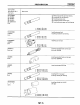
I FS5W71C PREPARATION Tool number (Kent-MooreNo Tool name I Description ST33400001 (J26082) Drift Installing rear oil seal ST33290001 (J25810-A) Puller Removing rear oil seal U Installing mainshaft ball bearing ST30720000 ( - ) Drift a 77 mm I3 03 inl dm b 55 5 mm 12 185 In) din ST30613000 (J25742-3) Drift Installing main drive gear bearing a b 71 5 mm 12 815 ml dm 47 5 mm I1 870 #"I daa ST33200000 (J260821 Drift Installing counter rear bearing Installing 3rd & 4th synchronizer assembly a
P RE PARATI0N (FS5R30AJ SPECIAL SERVICE TOOLS Tool number (Kent-Moore No ) Tool name - for FS5R3OA Description ~~ ST23540000 (J25689-A) Pin punch Removing and installing retaining pin ST30031000 (J22912-01) Puller Removing 1st & 2nd synchronizer assembly Removing counter gear rear thrust bearing Removing main drive bearing ST33290001 (J25810-A) Puller Removing rear oil seal ST33230000 Removing mainshaft and counter gear ( - ) Drift a 51 mm (2 01 in) dta b 28 5 m m I1 122 an) dia ST22350000
1- PREPARATION Tool number (Kent-Moore No ) Tool name Description ~ ST37750000 @ (J34286) @ (J34332) @ (534334) @ (525679-011 Drift @ @ 0 0 @ a b ST22452000 (534337) Drift 40mm1157# 31 m m I1 22 an1 dna / a a Removing counter gear rear bearing Installing 0 D gear bushing Installing reverse cone Installing reverse counter gear Installing counter gear rear end bearing 45 m m I177 Installing reverse hub Installing mainshaft rear bearing 14dm b 36 m m I142 in) dm ST33400001 (J26082) Drift Insta
pEiKl PREPARATION COMMERCIAL SERVICE TOOL Tool name - FS5R30A Description ~ Removing counter gear rear end bearing Removing mainshaft rear bearing Removing reverse synchronizer hub Removing reverse counter gear Puller MT-6
ON-VEHICLE SERVICE Checking M/T Oil Check manual transmission for leakage.
REMOVAL AND INSTALLATION Removal Remove exhaust front tube, catalytic converter and exhaust manifold connecting tube Refer to section EM. Remove propeller shaft. Refer to section PD Insert plug into rear oil seal after removing propeller shaft. 0 Support engine by placing a jack under oil pan CAUTION : 0 Be careful not to damage spline, sleeve yoke and rear oil seal, when removing propeller shaft. 0 Do not place jack under the oil pan drain plug. 0 Remove shift lever (FS5W71C).
MAJOR OVERHAUL MT-9 1-
MAJOR OVERHAUL Gear Components - FS5W71C Washer7 Maan drive gear ball bearing . . am drwe gear Shifting insert -&Y / flanrhaft ball bearing Mainshaft rear end bearmg Speedometer draw gear 1231 Without Tool Countershaft lock nut 'Overdrive 0 counter gear Reverse counter gear spacer k o u n t e r rear bearing Reverse idler gear Insert retainer Snap ring OD 0 Reverse idler thrust warhei hub verse Idler gear bearing counter drwe gear ..-...
MAJOR OVERHAUL IF S 5 W q Shift Control Components-FS5W71 C (With mainshaft braking mechanism) a MT-11
I FS5W71C I DISASSEMBLY Case Components 1 a v Remove rear extension Remove control housing, check ball, return spring plug, select check plunger and return springs SMT982 b. Remove rear extension by lightly tapping 2 It Remove front cover, gasket, shim of countershaft front bearing, and snap ring of main drive gear ball bearing 3. Separate transmission case from adapter plate TM753 I / 4 Remove oil seal of front cover Be careful not to damage mating surface of front cover.
DISASS E MB LY 1F K 1 Shift Control Components 1 2 Set up Tool on adapter plate. Remove check ball plugs, check springs, and check balls 3 Drive out retaining pins Then drive out fork rods and remove interlock balls 4 Remove lever bracket securing bolt. TM754 iR3540000 J25689-AI 5. Draw out 3rd4th fork rod. 6. Remove E-ring from 0.D.-rev. fork rod.
piiF] D ISASSE MBLY Shift Control Components (Cont'd) 7. Draw out 0 D.-rev. fork shaft by rotating 0.D.-rev bracket counterclockwise. I v UT025 Gear End play mm (in) 1S t 2nd 3rd OD 0 3 1 0 4 1 (00122-00161) 0 1 1 - 0 2 1 (00043-000831 0 11 0 21 (00043.0 0083) 0 32 - 0 39 ( 0 0 1 2 6 . 0 0154) 2 3 I r S u n a b l e puller 4 Mesh 2nd and reverse gear, then draw out counter front bearing with suitable puller.
DISASSEMBLY 1~ Gear Components (Cont'd) 5 a I Disassemble parts at rear of adapter plate as follows Release staking on countershaft nut and mainshaft nut and loosen these nuts Mainshaft nut: Left-hand thread SMTl63A I I Y b. Pull out 0.D counter gear with bearing with suitable puller c Draw out reverse counter gear and spacer d Remove snap rings from reverse idler shaft, and draw out reverse idler gear, thrust washers and reverse idler gear bearing e Remove speedometer drive gear and steel ball.
DISASSEMBLY 1- Gear Components (Cont'd) c d Press out 2nd main gear together with 1st gear bushing and 1st & 2nd synchronizer assembly Remove mainshaft front snap ring I n 2 9 1 2 0 11 e Press out 3rd main gear together with 3rd & 4th synchronizer assembly and 3rd gear needle bearing SMT385P 7. Remove main drive gear bearing a Remove snap ring and washer b Remove main drive gear bearing IJ.
INSPECTION 1- Shift Control Components I 0 Check contact surface and sliding surface of fork rods for wear, scratches, projections or other damage SMTl37 Gear Components GEARS AND SHAFTS Check shafts for cracks, wear or bending Check gears for excessive wear, chlps or cracks SMT386A Counter gear L SMT550r SYNCHRONIZERS Check spline portion of coupling sleeves, hubs and gears for wear or cracks 0 Check baulk rings for cracks or deformation.
Standard 1st&2nd 3rd & main drive SMT140 I 1 2 0 - 1 60 (00472.
ASS E M BLY Mainrhaft ball bearing in adapter plate 1- Gear Components 1 Install bearings into case components 2 Assemble adapter plate parts Install oil gutter on adapter plate and expand on rear side Counter rear bearing in adapter plate I , ' SMT153i a Install bearing retainer Insert reverse shaft, then install bearing retainer MT-19
I FS5W71C1 ASS E M BLY Gear Components (Cont'd) b Tighten each screw, then stake it at two points 3 Install main drive gear bearing a. Press in main drive gear bearing b Install main drive gear spacer Thickness mm (in) Part number 1 73 (00681) 32204-78005 1 80 (0 0709) 3220478000 1 87 (007361 32204-78001 1 94 (00764) 32204-78002 2 01 (00791) 3220478003 208(00819) 32204-78004 4.
ASS E M BLY 1 FS5W71C I Gear Components (Cont'd) 3rd and 4th I 8 ,Synchronizer hub I SMT024 0 D 15th) rvnehronlzer Ihub SMT095A Assemble 2nd main gear, needle bearing and 1st & 2nd synchronizer assembly, then press 1 s t gear bushing on mainshaft 6. Install 1 s t main gear. 5 . 7. Install steel ball and thrust washer Before installing steel ball and thrust washer, apply grease to them. 8 Press mainshaft assembly to adapter plate with Tool KV31100401 I - ) T..".
ASS EM BLY [FS5W71C I Gear Components (Cont’d) 9 Press counter gear into adapter plate with Tool 10. Install 3rd main gear and then press 3rd & 4th synchronizer assembly I Pay attention to direction of 3rd & 4th synchronizer. Front c SMT031 11 Install thrust washer on mainshaft and secure it with mainshaft front snap ring Select proper snap ring to minimize clearance of groove in mainshaft. Mainshaft front snap ring: Refer to S.D.S.
ASS EMBLY Gear Components (Cont'd) 14 Install sub-gear components a Install sub-gear and sub-gear bracket on counter drive gear and then select proper snap ring to minimize clearance of groove in counter gear Allowable clearance of groove: 0 0 18 rnm ( 0 - 0.
ASS E M BLY I FS5W71C I Gear Components (Cont'd) rlnrert shifting spring I b. Install insert retainer and O.D. synchronizer t o mainshaft Pay attention t o direction of hub 1 D 15th) synchronizer1 &" Nub SMT095A install 0 D gear bushing with Tool Install 0 D main gear and needle bearing e. Install spacer, reverse counter gear and 0 D counter gear O.D. main gear and 0 D. counter gear should be handled as a matched set f. Install washer, roller bearing, steel roller and thrust washer g.
ASS E MBLY I FS5W71C 1 Gear Components (Cont'd) Use the left chart when deciding the readmg torque (Length of torque wrench vs setting or reading torque) Torque wrench 1161 111010 -g ol 5 147 . I151 137 11001- 114) D L u 1901- 127 1131 118 . 112) (801-108 , MT004A Mainshaft 111 I1 51 12 01 12 51 I f 1 L Length of torque wrench Countershah 19.
ASS EMB LY IF S 5 W 7 q Shift Control Components (Cont'd) b 3rd-4th shift fork c 0 D -reverse shift fork SMT991 2. Install 0.D.-rev. fork shaft by rotating 0.D -rev bracket clockwise. SMT791A 3. Install E-ring on 0.D.-rev. fork rod. 4.
1- ASS EMBLY Case Components 1 Install front cover oil seal Apply multi-purpose grease to seal lip.
[Fs5w71cI ASSEMBLY Case Components (Cont’d) A A Distance from bearmg surface to transmisimn 7. Select counter front bearing shim Unit “A” I 4 52 - 4 71 4 32 - 4 41 (01701 - 0 1736) TU?, 4 22.4 31 (01661 . O 16971 412-421 (0 1622.0 1657) 4 0 2 - 4 11 (01583 - 0 1618) 3 92 - 4 01 (0 1543 - 0 1579) 8 9 Part number I 4 42 - 4 51 (01740 - 0 1776) 3 Counter gear I Not necessary (01780.
MAJOR OVERHAUL I FS5R30q SMTEZSA
MAJOR OVERHAUL Gear Components - FS5R30A MT-30 I FS5R30A I
MAJOR OVERHAUL 1 FS5R30A I Gear Components - FS5R30A (Cont’d) 1 SMT83OA MT-31
MAJOR OVERHAUL I FS5R30A I Shift Control Components - FS5R30A SMT838A MT-32
DISASSEMBLY I FS5R30A I Case Components 1 Remove checlc ball plug, check spring and check ball Then remove interlock stopper If interlock assembly is removed as a unit, the check ball can fall into transmission case. 2 Remove control housing, return spring and check ball 3 Drive out retaining pin from striking arm 4. Remove rear extension together with striking arm by tapping lightly.
DISASSEMBLY I FS5R30A I Case Components (Cont'd) Remove front cover and gasket Remove stopper ring and main drive bearing snap ring Remove transmission case by tapping lightly CMTR72A Remove front cover oil seal U SMT392A Shift Control Components 1 2 Mount adapter plate on vise Remove 0 D & reverse fork rod MT-34
I DISASSEMBLY FS5R30AJ Shift Control Components (Cont'd) 3. Remove check ball plug, check ball and return spring 4 5 Drive out retaining pin from striking lever While pulling out striking rod, remove striking lever and striking interlock Then remove 1st & 2nd. 3rd & 4th and reverse shift fork 6 Drive out retaining pin 3m 0 D shift ork 7. Pull out 0 D.
DISASSEMBLY I FS5R30AI Gear Components (Cont‘d) 2. Remove rear side components on mainshaft and counter gear. a. Remove snap ring, speedometer drive gear and steel ball b. Remove reverse coupling sleeve. c. Remove mainshaft rear snap ring and counter gear rear snap ring d. Remove C-ring holder and mainshaft C-rings from mainshaft Use punch and hammer to remove C-rings SMT377A e. Pull out counter gear rear end bearing f Remove reverse idler gear and reverse idler thrust washers g.
DISASSEMBLY 1FS5R30A I Gear Components (Cont'd) I. Pull out reverse main gear together with mainshaft spacer and reverse synchronizer hub Then remove reverse gear needle bearings SMT380L Pull out reverse counter gear k. Remove 0 D coupling sleeve together with 0 . D baulk ring, reverse baulk ring and spring inserts j I Pull out reverse gear bushing SMT770A m.
DISASS EM BLY Gear Components (Cont'd) 3 Press out mainshaft and counter gear alternately !I - Make sure to alternate press between r ,inshaft and wunter near not to allow the front surface of one to contact the rear surface of the other SMT772i 4 a b Remove front side components on mainshaft Remove 1st gear washer and steel ball Remove 1st main gear and 1st gear needle bearing c Press out 2nd main gear together with 1st gear bushing and 1st & 2nd synchronizer assembly Remove mainshaft front snap ri
I FS5R30A I DISASSEMBLY Gear Components (Cont'd) 5 a Remove front side components on counter gear Remove counter gear rear thrust bearing b Remove sub gear components. 6 Remove main drive gear bearing Remove main drive gear snap ring and spacer Press out main drive gear bearing SMT404D SMT470A a b ST30031000 /J2291201 I 7.
1- INSPECTION Shift Control Components ihift fork a I rmalnrhaft and gear Check contact surface and sliding surface for wear, scratches, projections or other damage Gear Components GEARS AND SHAFTS Check shafts for cracks, wear or bending a Check gears for excessive wear, chips or cracks a I SMT386A I Counter qear I SMT423A SYNCHRONIZERS a Check spline portion of coupling sleeves, hubs, and gears for wear or cracks a Check baulk rings for cracks or deformation a Check shifting inserts for wear
~ INSPECTION Gear Components (Cont'dl Dimens~on" A ' MT-41 (FS5R30Al Standard Wear limit -0 1 to 0 35 (-0 0039 to 0 0138) 0 7 (0028) -
[ FS5R30A I ASS EMBLY Gear Components 1 Sounter sear front bearing in transmission Install bearings into case components Mainshaft front bearing in adapter plate n SMT397A Counter gear rear bearing in adapter plate n KV38100300 SMT395A 2 a b Install main drive gear bearing Press main drive gear bearing Install main drive gear spacer Select proper main drive gear snap ring to minimize clearance of groove Allowable clearance of groove: 0 0 1 mm (0 - 0.
ASS E MBLY I FS5R30A I Gear Components (Cont'd) 3 a I ,Svnchronlzer I hub Install components on counter gear Install sub-gear components When installing sub-gear snap ring, tap sub-gear snap ring into position on counter gear.
ASS EMBLY Gear Components (Cont'd) Select proper snap ring to minimize clearance of groove Allowable clearance of groove' 0 - 0.1 mm ( 0 . 0.
piiq ASS E M BLY Gear Components (Cont'd) I 5 - Select proper counter gear front bearing shim when replacing transmission case, counter gear, counter gear thrust bearing or sub-gear components.
ASS E M BLY I FS5R30A 1 Reverse idler shaft Reverse idler front thrust washer -Reverse idler gear rear thrust washer Thickness mm (in) Part number A 1 97 (00776) 32284-01G10 B 2 07 ( 0 0815) 3228401G11 SMT432i b Place dial indicator on front end of reverse idler shaft c. Put straightedge on front surface of rear extension as a stopper of reverse idler shaft d Move reverse idler shaft up and down and measure reverse idler gear end play Reverse idler gear end play 0.30 - 0.53 mm ( 0 0118 - 0.
ASS EMBLY Gear Components (Cont'd) 7 a Push up with screwdriver7 Install mainsheft and counter gear on adapter plate and main drive gear on mainshaft Mount adapter plate on vise and apply multi-purpose grease to counter gear rear bearing b Install mainshaft a little on mainshaft front bearing To allow for installation of counter gear, do not install mainshaft completely. c.
ASSEMBLY I FS5R30A Gear Components (Cont’d) f Install mainshaft and counter gear completely by extending length of J26349-3 8 a Install rear side components on mainshaft and counter gear Install 0 D gear bushing while pushing on the front of counter gear b Install 0.D main gear Pay attention t o direction of O.D. main gear (B is wider than A as shown at left.) Install adapter plate with gear assembly onto transmission case Install O.D.
ASS E M BLV I FS5R30A I Gear Components (Cont'd) g Install insert siprings and reverse baulk ring on 0 D coupling sleeve. Then install them and 0 D baulk ring on 0 D counter gear Pay attention lo direction of O.D. coupling sleeve. h Install reverse counter gear I. Install sub-gear on reverse idler gear. Install reverse gear needle bearing and then install reverse main gear, reverse idler gear and reverse idler thrust washers. Reverse baulk ring 1. I I k. Install reverse hub.
IFS5R30A I ASS E MBLY Gear Components (Cont’d) 7 1 I. Install mainshaft spacer and mainshaft rear bearing m. Install speedometer drive gear. ST22452000 n Install counter gear rear end bearing 0 . Separate adapter plate from transmission case and Mount adapter plate on vice again P. Select proper mainshaft C-ring to minimize clearance of groove Allowable clearance of groove: 0 - 0.1 rnrn (0 - 0.
1 FS5R30A [ ASSEMBLY SMT453A Snap ring pliers s. Thickness mm (in) Part number 1 26 (0 0496) 32236-01G08 1 32 (0 0520) 32236-01GOO 1 38 (0 0543) 32236-01601 1 44 (0 0567) 32236-01602 1 50 (0 0591) 32236-01603 1 56 (0 0614) 32236-01604 1 62 (0 0638) 32236-01GO5 1 68 (00661 1 32236-01GO6 1 74 ( 0 0685) 32236-01607 Install selected counter gear rear snap ring Install reverse coupling sleeve Pay attention t o i t s direction. u.
ASS E MBLY [FS5R30A I Shift Control Components (Cont'd) 4. Install check ball, return spring and check ball plug. Apply sealant to thread of check ball plug. I Case components Install front cover oil seal Apply multi-purpose grease to seal lip. 2. Install selected counter gear front bearing shim onto transmission case Apply multi-purpose grease. 3 Apply sealant to mating surface of transmission case 1 4.
ASS E MB LV I FS5R30A I Case Components (Cont'd) 8 9 I I Install front cover and gasket Apply sealant to thread of 3 bolts shown left. Apply sealant i o mating surface of adapter plate SMT459A 10. Install rear extension together with striking arm. \ SMT461t 1 1 Install retaining pin into striking arm 12 Install return spring and check ball and then install control housing Apply sealant t o mating surface of rear extension.
~ SERVICE DATA AND SPECIFICATIONS (S.D.S.
1- SERVICE DATA AND SPECIFICATIONS (S.D.S.
pGZ.1 SERVICE DATA AND SPECIFICATIONS (S.D.S.
Thickness of proper warher Dial indicator d e f l e c t m rnm Iml 2 07 IO 08151 Part number 3228401611 mm 11") 0 9 3 .
SERVICE DATA AND SPECIFICATIONS (S.D.S.
Courtesy Nissan 1777 North Central Expressway Richardson, TX 75080 (800)527-1909 NISSAN FACTORY SERVICE MANUAL CDROM END-USER LICENSE AGREEMENT NOTICE TO USER: THIS IS A CONTRACT. BY PURCHASING AND USING THE SERVICE MANUAL ON CDROM, YOU ACCEPT ALL THE TERMS AND CONDITIONS OF THIS AGREEMENT. This End User License Agreement accompanies the Service Manual on CDROM product and related explanatory materials. Please read this Agreement carefully.
Courtesy Nissan 1777 North Central Expressway Richardson, TX 75080 (800)527-1909 GOVERNING LAW AND GENERAL PROVISIONS This Agreement will be governed by the laws of the State of Texas, USA, excluding the application of its conflicts of law rules. This Agreement will not be governed by the United Nations Convention on Contracts for the International Sale of Goods, the application of which is expressly excluded.