J AIR CONDITIONER A SECTION MANUAL AIR CONDITIONER B C D CONTENTS PRECAUTIONS .......................................................... 3 Precautions for Supplemental Restraint System (SRS) “AIR BAG” and “SEAT BELT PRE-TENSIONER” .................................................................. 3 Precautions for Working with HFC-134a (R-134a)..... 3 Contaminated Refrigerant ........................................ 3 General Refrigerant Precautions ..............................
MIX DOOR .......................................................... 44 Temperature Control Linkage Adjustment .............. 45 BLOWER MOTOR .................................................... 46 Trouble Diagnosis Procedure for Blower Motor ...... 46 Blower Motor Circuit ............................................... 46 Electrical Components Inspection .......................... 50 FAN CONTROL SWITCH .................................... 50 BLOWER MOTOR ...............................................
PRECAUTIONS PRECAUTIONS PFP:00001 Precautions for Supplemental Restraint System (SRS) “AIR BAG” and “SEAT BELT PRE-TENSIONER” A EJS001QX The Supplemental Restraint System such as “AIR BAG” and “SEAT BELT PRE-TENSIONER”, used along with a front seat belt, helps to reduce the risk or severity of injury to the driver and front passenger for certain types of collision. Information necessary to service the system safely is included in the SRS and SB section of this Service Manual.
PRECAUTIONS ● If the vehicle is within the warranty period, the air conditioner warranty is void. Please contact Nissan Customer Affairs for further assistance. General Refrigerant Precautions EJS001A9 WARNING: ● Do not release refrigerant into the air. Use approved recovery/recycling equipment to capture the refrigerant every time an air conditioning system is discharged. ● Always wear eye and hand protection (goggles and gloves) when working with any refrigerant or air conditioning system.
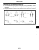
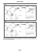
PRECAUTIONS Precautions for Refrigerant Connection EJS001AC A FEATURES OF NEW TYPE REFRIGERANT CONNECTION ● ● The O-ring has been relocated. It has also been provided with a groove for proper installation. This eliminates the chance of the O-ring being caught in, or damaged by, the mating part. The sealing direction of the O-ring is now set vertically in relation to the contacting surface of the mating part to improve sealing characteristics.
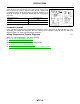
PRECAUTIONS O-RING AND REFRIGERANT CONNECTION QG18DE WJIA0417E QR25DE WJIA0418E CAUTION: The new and former refrigerant connections in some systems use different O-ring configurations. Do not confuse O-rings since they are not interchangeable. If a wrong O-ring is installed, refrigerant will leak at, or around, the connection.
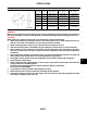
PRECAUTIONS O-Ring Part Numbers and Specifications SHA814E A Connection type O-ring size Part number* D New 8 92471 N8210 6.8 (0.268) 1.85 (0.0728) Former 12 92475 71L00 10.8 (0.425) 1.78 (0.0701) New 12 92472 N8210 10.9 (0.429) 3.65 (0.1437) Former 16 92475 72L00 13.9 (0.547) 1.78 (0.0701) New 16 92473 N8210 13.6 (0.535) 2.43 (0.0957) New 19 92474 N8210 16.5 (0.650) 2.43 (0.
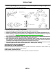
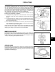
PRECAUTIONS ● After connecting line, conduct leak test and make sure that there is no leakage from connections. When the gas leaking point is found, disconnect that line and replace the O-ring. Then tighten connections of seal seat to the specified torque. RHA861F Precautions for Servicing Compressor ● ● ● ● ● ● EJS001AD Plug all openings to prevent moisture and foreign matter from entering. When the compressor is removed, store it in the same position as it is when mounted on the car.
PRECAUTIONS VACUUM PUMP A The lubricant contained inside the vacuum pump is not compatible with the specified lubricant for HFC-134a (R-134a) A/C systems. The vent side of the vacuum pump is exposed to atmospheric pressure so the vacuum pump lubricant may migrate out of the pump into the service hose. This is possible when the pump is switched off after evacuation (vacuuming) and hose is connected to it. To prevent this migration, use a manual valve situated near the hose-to-pump connection, as follows.
PRECAUTIONS SERVICE COUPLERS Never attempt to connect HFC-134a (R-134a) service couplers to an CFC-12 (R-12) A/C system. The HFC-134a (R-134a) couplers will not properly connect to the CFC-12 (R-12) system. However, if an improper connection is attempted, discharging and contamination may occur. Shut-off valve rotation A/C service valve Clockwise Open Counterclockwise Close RHA273D CHARGING CYLINDER Using a charging cylinder is not recommended.
PREPARATION PREPARATION Special Service Tools PFP:00002 A EJS001AG Tool number (Kent-Moore No.
PREPARATION HFC-134a (R-134a) Service Tools and Equipment EJS001AH Never mix HFC-134a refrigerant and/or its specified lubricant with CFC-12 (R-12) refrigerant and/or its lubricant. Separate and non-interchangeable service equipment must be used for handling each type of refrigerant/lubricant. Refrigerant container fittings, service hose fittings and service equipment fittings (equipment which handles refrigerant and/or lubricant) are different between CFC-12 (R-12) and HFC-134a (R-134a).
PREPARATION Tool number (Kent-Moore No.) Tool name (J-42220) Fluorescent dye leak detector Description A Power supply: DC 12V (Battery terminal) For checking refrigerant leak when fluorescent dye is installed in A/C system. Includes: UV lamp and UV safety glasses B C SHA438F (J-41447) HFC-134a (R-134a) Fluorescent leak detection dye (Box of 24, 1/4 ounce bottles) D Application: For HFC-134a (R-134a) PAG oil Container: 1/4 ounce (7.
PREPARATION Tool number (Kent-Moore No.) Tool name Description Service couplers ● ● High side coupler (J-39500-20) Hose fitting to service hose: Low side coupler (J-39500-24) ● M14 x 1.5 fitting is optional or permanently attached.
REFRIGERATION SYSTEM REFRIGERATION SYSTEM Refrigeration Cycle PFP:KA990 A EJS001AI REFRIGERANT FLOW The refrigerant flows in the standard pattern, that is, through the compressor, the condenser, the liquid tank, through the evaporator, and back to the compressor. The refrigerant evaporation through the evaporator coil is controlled by an externally equalized expansion valve, located inside the evaporator case.
LUBRICANT LUBRICANT Maintenance of Lubricant Quantity in Compressor PFP:KLG00 EJS001AJ The lubricant in the compressor circulates through the system with the refrigerant. Add lubricant to compressor when replacing any component or after a large refrigerant leakage has occurred. It is important to maintain the specified amount.
LUBRICANT Lubricant Adjusting Procedure for Components Replacement Except Compressor After replacing any of the following major components, add the correct amount of lubricant to the system. Amount of lubricant to be added Lubricant to be added to system Part replaced Amount of lubricant ml (US fl oz, Imp fl oz) B Remarks Evaporator 75 (2.5, 2.6) — Condenser 75 (2.5, 2.6) — Liquid tank 5 (0.2, 0.2) Add if compressor is not replaced. 30 (1.0, 1.
LUBRICANT RHA065DD MTC-18
TROUBLE DIAGNOSIS TROUBLE DIAGNOSIS Component Layout PFP:00004 A EJS001AK B C D E F G H I MTC K L M WJIA0257E MTC-19
TROUBLE DIAGNOSIS Control Operation EJS001AL LHA109 FAN CONTROL SWITCH This switch turns the fan ON and OFF, and controls fan speed. REAR WINDOW DEFOGGER SWITCH This switch turns the rear window defogger ON and OFF. MODE CONTROL KNOB This control knob controls the outlet air flow. When DEF or F/D mode is selected, the push control unit sets the intake door to FRESH. The compressor turns on when DEF mode is selected and remains on until the key is turned off.
TROUBLE DIAGNOSIS Discharge Air Flow EJS001AM A B C D E F G H I MTC K L M LHA127 MTC-21
TROUBLE DIAGNOSIS System Description EJS001AN SWITCHES AND THEIR CONTROL FUNCTIONS Knob/Switch position Knob/Switch A/C A/C Mode Air outlet Intake air Compressor — — ON*1 FACE — — B/L — — FOOT — — F/D FRE — DEF FRE ON*1 — REC*2 — *1: Compressor operation is controlled by the ECM (when the compressor is activated in DEF mode, it remains on until the key is turned off). *2: In DEF and F/D modes, REC switch is canceled.
TROUBLE DIAGNOSIS Component Location EJS001AO A ENGINE COMPARTMENT B C D E F G H I MTC K L M WJIA0248E MTC-23
TROUBLE DIAGNOSIS PASSENGER COMPARTMENT WJIA0249E MTC-24
TROUBLE DIAGNOSIS Wiring Diagram — Heater — EJS001AP A QG18DE MODELS B C D E F G H I MTC K L M WJWA0052E MTC-25
TROUBLE DIAGNOSIS ECM TERMINALS AND REFERENCE VALUE MEASURED BETWEEN EACH TERMINAL AND GROUND TERMINAL WIRE COLOR ITEM CONDITION 96 Y/G FAN CONTROL SWITCH DATA (DC) FAN CONTROL SWITCH "ON" (ENGINE RUNNING) APPROX. 0V FAN CONTROL SWITCH "OFF" (ENGINE RUNNING) APPROX.
TROUBLE DIAGNOSIS Wiring Diagram — A/C, M — EJS001AQ A QG18DE MODELS B C D E F G H I MTC K L M WJWA0053E MTC-27
TROUBLE DIAGNOSIS ECM TERMINALS AND REFERENCE VALUE MEASURED BETWEEN EACH TERMINAL AND GROUND TERMINAL WIRE COLOR ITEM CONDITION 96 110 Y/G L/R FAN CONTROL SWITCH AIR CONDITIONER SWITCH SIGNAL DATA (DC) FAN CONTROL SWITCH "ON" (ENGINE RUNNING) APPROX. 0V FAN CONTROL SWITCH "OFF" (ENGINE RUNNING) APPROX. 5V BOTH A/C SWITCH AND BLOWER SWITCH "ON" (ENGINE RUNNING) APPROX.
TROUBLE DIAGNOSIS A B C D E F G H I MTC K L M WJWA0054E MTC-29
TROUBLE DIAGNOSIS ECM TERMINALS AND REFERENCE VALUE MEASURED BETWEEN EACH TERMINAL AND GROUND TERMINAL WIRE COLOR ITEM CONDITION DATA (DC) 49 R/L SENSOR POWER SUPPLY IGNITION SWITCH "ON" APPROX. 5.0V 67 B/W ECM GROUND IDLE SPEED (ENGINE RUNNING) 1V OR LESS REFRIGERANT PRESSURE SENSOR BOTH A/C SWITCH AND BLOWER SWITCH "ON" (ENGINE RUNNING, WARM-UP CONDITION, COMPRESSOR OPERATING) 0.36 - 3.88V BOTH A/C SWITCH AND BLOWER SWITCH "ON" (ENGINE RUNNING) (COMPRESSOR OPERATING) 0 - 1.
TROUBLE DIAGNOSIS QR25DE MODELS A B C D E F G H I MTC K L M WJWA0055E MTC-31
TROUBLE DIAGNOSIS ECM TERMINALS AND REFERENCE VALUE MEASURED BETWEEN EACH TERMINAL AND GROUND TERMINAL WIRE COLOR ITEM CONDITION 96 110 Y/G L/R FAN CONTROL SWITCH AIR CONDITIONER SWITCH SIGNAL DATA (DC) FAN CONTROL SWITCH "ON" (ENGINE RUNNING) APPROX. 0V FAN CONTROL SWITCH "OFF" (ENGINE RUNNING) APPROX. 5V BOTH A/C SWITCH AND BLOWER SWITCH "ON" (ENGINE RUNNING) APPROX.
TROUBLE DIAGNOSIS A B C D E F G H I MTC K L M WJWA0056E MTC-33
TROUBLE DIAGNOSIS ECM TERMINALS AND REFERENCE VALUE MEASURED BETWEEN EACH TERMINAL AND GROUND TERMINAL WIRE COLOR ITEM CONDITION DATA (DC) 49 R/Y SENSOR POWER SUPPLY IGNITION SWITCH "ON" APPROX. 5.0V 58 B/W ECM GROUND IDLE SPEED (ENGINE RUNNING) 1V OR LESS REFRIGERANT PRESSURE SENSOR BOTH A/C SWITCH AND BLOWER SWITCH "ON" (ENGINE RUNNING, WARM-UP CONDITION, COMPRESSOR OPERATING) 0.36 - 3.88V BOTH A/C SWITCH AND BLOWER SWITCH "ON" (ENGINE RUNNING) (COMPRESSOR OPERATING) 0 - 1.
TROUBLE DIAGNOSIS Operational Check EJS001AS A The purpose of the operational check is to confirm that the system operates properly. CONDITIONS: ● Engine running and at normal operating temperature. B PROCEDURE: 1. Check Blower C 1. Turn fan control switch to 1-speed. Blower should operate on 1-speed. 2. Then turn fan control switch to 2-speed, and continue checking blower speed until all speeds are checked. 3. Leave fan control switch on 4-speed.
TROUBLE DIAGNOSIS 3. Check Recirculation 1. Press REC switch. Recirculation indicator should illuminate. 2. Listen for intake door position change (you should hear blower sound change slightly). If NG, go to MTC-38, "Trouble Diagnosis Procedure for Intake Door" . If OK, continue with next check. NOTE: ● Recirculation does not operate in DEF modes. and F/D LHA112 4. Check Temperature Decrease 1. Turn temperature control knob to full cold. 2. Check for cold air at discharge air outlets.
TROUBLE DIAGNOSIS Main Power Supply and Ground Circuit Check EJS001AT A POWER SUPPLY CIRCUIT CHECK Check power supply circuit for air conditioner system. Refer to PG-5, "Wiring Diagram — POWER —" .
INTAKE DOOR INTAKE DOOR Trouble Diagnosis Procedure for Intake Door PFP:27245 EJS001AU SYMPTOM: ● Intake door does not change. INSPECTION FLOW LHA142 *1 MTC-39 *2 MTC-35 *3 Component Description MTC-34 EJS001AV INTAKE DOOR MOTOR The intake door motor is installed on the intake unit. Using a link, it opens and closes the intake door. When REC switch is ON, the ground line of the motor is switched from terminal 2 to 1.
INTAKE DOOR Intake Door Motor Circuit EJS001AW A SYMPTOM: ● Intake door does not change. B 1. CHECK POWER SUPPLY FOR INTAKE DOOR MOTOR Disconnect intake door motor harness connector. Do approx. 12 volts exist between intake door motor harness terminal Nos. 1, 2 and body ground? C D E F LHA168 Yes or No Yes >> GO TO 3. No >> GO TO 2.
INTAKE DOOR 2. CHECK CIRCUIT CONTINUITY BETWEEN INTAKE DOOR MOTOR AND AIR CONTROL UNIT Check circuit continuity between A/C control unit harness terminal Nos. 10 (11) and intake door motor harness terminal Nos. 2 (1). LHA140 If OK, check harness for short. Yes or No Yes >> Replace A/C control unit. No >> Repair harness or connector. 3. CHECK CIRCUIT CONTINUITY OF INTAKE DOOR MOTOR Check circuit continuity between intake door motor harness terminal No. 1 and No. 2. LHA139 OK or NG OK >> GO TO 4.
INTAKE DOOR 4. CHECK INTAKE DOOR LINKAGE A Refer to MTC-43, "CONTROL LINKAGE ADJUSTMENT" . OK or NG OK >> INSPECTION END. NG >> Repair or adjust. Control Linkage Adjustment B EJS001AX INTAKE DOOR MOTOR 1. 2. 3. 4. Install intake door motor on intake unit. Ensure that the intake door motor lever is fitted into the slit portion of intake door link. Connect the intake door motor harness connector. Turn ignition switch to “ON” position.
INTAKE DOOR Mode Door EJS001AY TROUBLE DIAGNOSIS PROCEDURE FOR MODE DOOR SYMPTOM: ● Mode door does not change.
INTAKE DOOR CONTROL LINKAGE ADJUSTMENT Mode Door Control Linkage ● ● ● ● A Turn mode door control knob to position. Set side link in DEF mode. Pull on outer cable in direction of arrow and then clamp it. After positioning mode door control cable, check that it operates properly.
INTAKE DOOR Air Mix Door EJS001AZ TROUBLE DIAGNOSIS PROCEDURE FOR AIR MIX DOOR SYMPTOM: ● Air mix door does not change.
INTAKE DOOR Temperature Control Linkage Adjustment EJS001B0 A Temperature Control Cable ● Turn temperature control knob to the full cold position. ● Set the air mix door lever in the full cold position by hand. ● Pull on cable cover in the direction of the arrow and then clamp cable cover. After positioning air mix door control cable, check for proper operation.
BLOWER MOTOR BLOWER MOTOR Trouble Diagnosis Procedure for Blower Motor PFP:27226 EJS001B1 SYMPTOM: ● Blower motor does not rotate at all. INSPECTION FLOW LHA138 *1 MTC-46 *2 MTC-35 *3 Blower Motor Circuit EJS001B2 SYMPTOM: ● Blower motor does not rotate. Symptom table No. MTC-34 INCIDENT 1 Fan fails to rotate. 2 Fan does not rotate at 1-speed. 3 Fan does not rotate at 2-speed. 4 Fan does not rotate at 3-speed. 5 Fan does not rotate at 4-speed. 1.
BLOWER MOTOR 2. CHECK POWER SUPPLY FOR BLOWER MOTOR 1. 2. A Disconnect blower motor harness connector. Do approx. 12 volts exist between blower motor harness terminal + and body ground? B C D LHA137 E Yes or No Yes >> GO TO 3. No >> Check 15A (Nos. 14 and 16) fuses at fuse block. Refer to PG-9, "IGNITION POWER SUPPLY — IGNITION SW. IN “ON”" . F 3. CHECK CIRCUIT CONTINUITY FOR BLOWER MOTOR G 1. 2. H Turn fan control switch to any position except OFF.
BLOWER MOTOR 5. CHECK BLOWER MOTOR CIRCUIT BETWEEN BLOWER MOTOR AND FAN RESISTOR Do approx. 12 volts exist between fan resistor harness terminal No. 1 and body ground? LHA135 Yes or No Yes >> Disconnect fan control switch harness connector. GO TO 7. No >> Disconnect blower motor and fan resistor harness connectors. GO TO 6. 6. CHECK CIRCUIT CONTINUITY BETWEEN BLOWER MOTOR AND FAN RESISTOR Check circuit continuity between blower motor harness terminal – and fan resistor harness terminal No. 1.
BLOWER MOTOR 8. CHECK RESISTOR AFTER DISCONNECTING IT A Refer to MTC-50, "FAN RESISTOR" . OK or NG OK >> GO TO 9. NG >> Replace fan resistor. B 9. CHECK FAN RESISTOR HARNESS CONNECTOR C Reconnect fan resistor harness connector. D 1 >> GO TO 12. 2, 3, 4 >> GO TO 10. 10. CHECK FAN CONTROL SWITCH CIRCUIT E Do approx. 12 volts exist between each fan control switch harness terminal and body ground? F G H LHA131 Yes or No Yes >> GO TO 12. No >> GO TO 11. I MTC 11.
BLOWER MOTOR Electrical Components Inspection EJS001B3 FAN CONTROL SWITCH Check continuity between terminals at each switch position. Fan control switch position Continuity between terminals OFF 1 4—5—6 2 3—5—6 3 2—5—6 4 1—5—6 LHA163 BLOWER MOTOR Confirm smooth rotation of the blower motor. ● Ensure that there are no foreign particles inside the intake unit. FAN RESISTOR Check resistance between terminals. Terminal No. (+) (−) 3 4 2 Resistance (Approx.) 1.305 - 1.595Ω 1 2.457 - 3.003Ω 0.
MAGNET CLUTCH MAGNET CLUTCH Trouble Diagnosis Procedure for Magnet Clutch PFP:92660 A EJS001B4 SYMPTOM: ● Magnet clutch does not operate when A/C switch and fan control switch are ON.
MAGNET CLUTCH Magnet Clutch Circuit EJS001B5 SYMPTOM: ● Magnet clutch does not engage when A/C switch and fan control switch are ON. 1. CHECK POWER SUPPLY FOR COMPRESSOR Disconnect compressor harness connector. Do approx. 12 volts exist between compressor harness connector E36 terminal 1, (L/R) and body ground? WHA256 Yes or No Yes >> GO TO 2. No >> GO TO 3. 2. CHECK MAGNET CLUTCH COIL Disconnect magnet clutch connector. Do approx. 3.
MAGNET CLUTCH 3. CHECK CIRCUIT CONTINUITY BETWEEN A/C RELAY AND COMPRESSOR HARNESS A Disconnect A/C relay. Check circuit continuity between A/C relay harness terminal 3 and compressor harness terminal 1. B C D LHA149 If OK, check harness for short. OK or NG OK >> GO TO 4. NG >> Repair harness or connector. E F 4. CHECK INTAKE SENSOR CIRCUIT G Refer to MTC-66, "Intake Sensor Circuit" . OK or NG OK >> GO TO 5. NG >> Repair as necessary. H 5.
MAGNET CLUTCH 7. CHECK COIL SIDE CIRCUIT OF A/C RELAY Reconnect A/C relay. Do approx. 12 volts exist between ECM harness connector F59 terminal 105 (L) and body ground? Battery voltage should exist. Yes or No Yes >> GO TO 9. No >> Disconnect A/C relay. Disconnect ECM harness connector. GO TO 8. WJIA0376E 8. CHECK CIRCUIT CONTINUITY BETWEEN A/C RELAY AND ECM HARNESS Check circuit continuity between A/C relay harness connector E50 terminal 2 (L) and ECM harness connector F59 terminal 105 (L).
MAGNET CLUTCH 11. CHECK CIRCUIT CONTINUITY BETWEEN FAN CONTROL SWITCH AND A/C CONTROL UNIT Disconnect A/C control unit and fan control switch. Check circuit continuity between fan control switch harness connector M31 terminal No. 6 (Y/G) and A/C control unit harness connector M32 terminal No. 8 (Y/G). A B Continuity should exist. C If OK, check harness for short. OK or NG OK >> GO TO 12. NG >> Repair harness or connector. D WJIA0263E E 12.
MAGNET CLUTCH REFRIGERANT PRESSURE SENSOR BBIA0165E Make sure that higher A/C refrigerant pressure results in higher refrigerant pressure sensor output voltage.
INSUFFICIENT COOLING INSUFFICIENT COOLING Trouble Diagnosis Procedure for Insufficient Cooling PFP:00000 A EJS001B7 SYMPTOM: ● Insufficient cooling B INSPECTION FLOW C D E F G H I MTC K L M WJIA0364E *1 MTC-42 *2 MTC-61 *3 MTC-58 *4 MTC-35 *5 MTC-34 *6 MTC-80 *7 EC-1092 *8 EC-1092 *9 MA-17 (QG18DE) or MA-24 (QR25DE) *11 MTC-66 *10 MTC-3 MTC-57
INSUFFICIENT COOLING Performance Test Diagnoses EJS001B8 LHA196 *1 MTC-60 *2 MTC-61 MTC-58
INSUFFICIENT COOLING A B C D E F G H I MTC K L M WJIA0008E *1 MTC-51 *2 MA-16 *3 MTC-59 MA-23
INSUFFICIENT COOLING Performance Chart EJS001B9 The Nissan A/C system uses a thermal expansion valve to provide a restriction which causes a pressure change and also controls refrigerant flow through the evaporator. The best way to diagnose a condition in the refrigerant system is to note the system pressures (shown by the manifold gauges) and the clutch cycle rate and times. Then, compare the findings to the charts. ● The system pressures are low (compressor suction) and high (compressor discharge).
INSUFFICIENT COOLING Trouble Diagnoses for Abnormal Pressure EJS001BA Whenever system's high and/or low side pressure is abnormal, diagnose using a manifold gauge. The marker above the gauge scale in the following tables indicates the standard (normal) pressure range. However, since the standard (normal) pressure differs from vehicle to vehicle, refer to MTC-60, "Ambient Air Temperature-toOperating Pressure Table" . A B BOTH HIGH AND LOW-PRESSURE SIDES ARE TOO HIGH.
INSUFFICIENT COOLING HIGH-PRESSURE SIDE IS TOO LOW AND LOW-PRESSURE SIDE IS TOO HIGH. Gauge indication High-pressure side is too low and low-pressure side is too high. Refrigerant cycle Probable cause Corrective action High and low-pressure sides become equal soon after compressor operation stops. Compressor pressure operation is improper. ↓ Damaged inside compressor packings Replace compressor. No temperature difference between high and low-pressure sides Compressor pressure operation is improper.
INSUFFICIENT COOLING LOW-PRESSURE SIDE SOMETIMES BECOMES NEGATIVE. Gauge indication Low-pressure side sometimes becomes negative. Refrigerant cycle ● ● Air conditioning system does not function and does not cyclically cool the compartment air. The system constantly functions for a certain period of time after compressor is stopped and restarted. Probable cause Refrigerant does not discharge cyclically. ↓ Moisture is frozen at expansion valve outlet and inlet. ↓ Water is mixed with refrigerant.
INSUFFICIENT HEATING INSUFFICIENT HEATING Trouble Diagnosis Procedure for Insufficient Heating PFP:00000 EJS001BB Symptom: ● Insufficient heating Inspection Flow WJIA0009E *1 MTC-41 *2 MTC-35 *3 MTC-34 *4 MA-17 *5 MA-24 *6 CO-9 *7 CO-36 *8 CO-12 *9 CO-30 *10 MA-19 *11 MA-25 MTC-64
NOISE NOISE Trouble Diagnosis Procedure for Noise PFP:00004 A EJS001BC SYMPTOM: ● Noise B INSPECTION FLOW C D E F G H I MTC K L M WJIA0214E *1 MTC-69 *2 MTC-72 *4 MA-16 *5 MA-23 *3 MTC-65 MTC-16
INTAKE SENSOR INTAKE SENSOR Intake Sensor Circuit PFP:27723 EJS001GW COMPONENT DESCRIPTION Intake Sensor The intake sensor is located on the heater and cooling unit. It converts temperature of air after it passes through the evaporator into a resistance value which is then input to the A/C control unit. After disconnecting intake sensor harness connector, measure resistance between terminals 1 and 2 at sensor harness side, using the table below. Temperature °C (°F) Resistance kΩ -15 (5) 12.
INTAKE SENSOR 2. CHECK INTAKE SENSOR CIRCUIT BETWEEN INTAKE SENSOR AND A/C CONTROL UNIT A Disconnect A/C control unit harness connector. Terminals (+) (–) Connector Terminal No. (Wire color) Connector Terminal No. (Wire color) M49 1 (GY) M32 12 (GY) Continuity B Yes C OK or NG OK >> GO TO 3. NG >> Repair harness or connector. D WJIA0265E 3. CHECK INTAKE SENSOR E Refer to MTC-66, "Intake Sensor Circuit" . OK or NG OK >> Replace A/C control unit. NG >> Replace intake sensor.
COMPRESSOR COMPRESSOR Removal and Installation PFP:92600 EJS001BD LHA121 WJIA0011E MTC-68
COMPRESSOR CLUTCH COMPRESSOR CLUTCH Overhaul PFP:92600 A EJS001BE QG18DE B C D E F G WJIA0267E QR25DE H I MTC K L M WJIA0268E MTC-69
COMPRESSOR CLUTCH Removal EJS001BF QG18DE ● ● When removing center bolt, hold clutch disc with clutch disc tool. Remove the clutch disc. Clutch disc holding tool: (J-44614) Commercial service tool WHA228 ● Remove the snap ring using external snap ring pliers. RHA072C ● Pulley removal: LHA173 WHA212 ● ● Use a pulley puller with small adapter. Position the small adapter on the end of the drive shaft and the center of the puller on the small adapter. Remove the pulley assembly with the puller.
COMPRESSOR CLUTCH QR25DE ● ● A When removing center bolt, hold clutch disc with clutch disc tool. Remove the drive plate using the clutch disc puller. Insert the holder's three pins into the drive plate. Rotate the holder clockwise to hook it onto the plate. Then tighten the center bolt to remove the drive plate. While tightening the center bolt, insert a round bar (screwdriver, etc.) between two of the pins (as shown in the figure) to prevent drive plate rotation.
COMPRESSOR CLUTCH ● Remove the three field coil fixing screws and remove the field coil. RHA074C Inspection EJS001BG CLUTCH DISC If the contact surface shows signs of damage due to excessive heat, replace clutch disc and pulley. WHA183 PULLEY Check the appearance of the pulley assembly. If contact surface of pulley shows signs of excessive grooving, replace clutch disc and pulley. The contact surfaces of the pulley assembly should be cleaned with a suitable solvent before reinstallation.
COMPRESSOR CLUTCH ● Install the clutch disc on the drive shaft, together with the original shim(s). Press the clutch disc down using the drive plate installer. A B C WHA184 D ● ● Using the clutch disc tool to prevent clutch disc rotation, tighten the bolt to 12 to 15 N·m (1.2 to 1.5 kg-m, 9 to 11 ft-lb) torque. After tightening the bolt, check that the pulley rotates smoothly. E F G WHA229 ● Check clearance all the way around the clutch disc. Clutch disc-to-pulley clearance H : 0.3 - 0.
COMPRESSOR CLUTCH QR25DE ● ● Install the field coil. Be sure to align the magnet coil pin with the hole in the compressor front head. Install the magnet coil harness clip using a screwdriver. RHA076C ● Install the pulley assembly using the installer, and then install the snap ring using snap ring pliers. WJIA0368E ● Install the drive plate on the drive shaft, together with the original shim(s). Press the drive plate down with the installer.
COMPRESSOR CLUTCH ● Check clearance all the way around the clutch disc. Clutch disc-to-pulley clearance A : 0.3 - 0.6 mm (0.012 - 0.024 in) If the specified clearance is not obtained, replace adjusting spacer and readjust. B C D E F G AHA505A Break-In Operation EJS001BI When replacing compressor clutch assembly, always conduct the break-in operation. This is done by engaging and disengaging the clutch about 30 times. Break-in operation raises the level of transmitted torque.
THERMAL PROTECTOR THERMAL PROTECTOR Inspection ● PFP:27631 EJS001BJ Check continuity between terminal and ground.
IN-CABIN MICROFILTER IN-CABIN MICROFILTER Removal and Installation PFP:27277 A EJS001GX FUNCTION Air inside passenger compartment is kept clean at either recirculation or fresh mode by installing in-cabin microfilter into blower unit. B C D LJIA0012E E REPLACEMENT TIMING Refer to MA-7, "Schedule 1" or MA-11, "Schedule 2" . Caution label is affixed inside the glove box. F REPLACEMENT PROCEDURES 1. 2. 3. 4. 5. Remove glove box assembly. Refer to IP-10, "Removal and Installation" .
HEATER & COOLING UNIT (HEATER CORE) HEATER & COOLING UNIT (HEATER CORE) Removal PFP:27110 EJS001BK LHA203 1. 2. 3. 4. 5. 6. Drain the cooling system. Refer to MA-16, "DRAINING ENGINE COOLANT" (QG18DE), or MA-23, "DRAINING ENGINE COOLANT" (QR25DE). Discharge the A/C system. Refer to MTC-82, "Discharging Refrigerant" . Disconnect the two heater hoses from inside the engine compartment. Remove the instrument panel assembly and steering member assembly. Refer to IP-10, "INSTRUMENT PANEL ASSEMBLY" .
BLOWER UNIT BLOWER UNIT Removal PFP:27200 A EJS001BM B C D E F G H I LHA204 1. 2. 3. 4. 5. 6. 7. Discharge the A/C system. Refer to MTC-82, "Discharging Refrigerant" . Disconnect the two refrigerant lines from the engine compartment. Cap the A/C lines to prevent moisture from entering the system. Remove the glove box and mating trim. Refer to IP-10, "Removal and Installation" . Remove cooling unit. Refer to MTC-80, "Removal" . Disconnect the resistor and blower motor connector.
A/C EVAPORATOR A/C EVAPORATOR Removal PFP:27280 EJS001BO LHA181 1. 2. Discharge the A/C system. Refer to MTC-82, "Discharging Refrigerant" . Remove clamp bolt and remove low-pressure and high-pressure lines from cooling unit (expansion valve). Remove lines from retaining clip on dash panel and move lines away from dash panel for clearance. 3. Install caps over cooling unit (expansion valve) ports and lines. 4. Remove both side front console side covers. 5.
A/C EVAPORATOR 13. Mark installation point of intake sensor and remove intake sensor from evaporator core. 14. Remove evaporator core from case by sliding forward off of case retaining tabs. 15. Remove expansion valve from evaporator core (if necessary). A B C WJIA0254E D Installation EJS001BP Installation is the reverse of removal*. Recharge the A/C system. Refer to MTC-82, "Evacuating System and Charging Refrigerant" .
REFRIGERANT LINES REFRIGERANT LINES HFC-134a (R-134a) Service Procedure PFP:92600 EJS001BQ SETTING OF SERVICE TOOLS AND EQUIPMENT Discharging Refrigerant WARNING: Avoid breathing A/C refrigerant and lubricant vapor or mist. Exposure may irritate eyes, nose and throat. Remove HFC-134a (R-134a) from A/C system using certified service equipment meeting requirements of SAE J2210 (R-134a recycling equipment) or J2209 (R-134a recovery equipment).
REFRIGERANT LINES A B C D E F G H I MTC K L M WJIA0382E *1 MTC-16 *2 MTC-86 *3 MTC-87 *4 MTC-58 *5 MTC-3 *6 MTC-91 MTC-83
REFRIGERANT LINES Removal and Installation ● EJS001BR Refer to MTC-5, "Precautions for Refrigerant Connection" .
REFRIGERANT LINES QR25DE A B C D E F G H I MTC K L M WJIA0421E MTC-85
REFRIGERANT LINES Checking Refrigerant Leaks EJS001BS PRELIMINARY CHECK Perform a visual inspection of all refrigeration parts, fittings, hoses and components for signs of A/C lubricant leakage, damage and corrosion. A/C lubricant leakage may indicate an area of refrigerant leakage. Allow extra inspection time in these areas when using either an electronic refrigerant leak detector or fluorescent dye leak detector.
REFRIGERANT LINES 3. Move probe along component approximately 25 to 50 mm (1 to 2 in)/sec. A B C SHA708EA D CHECKING PROCEDURE To prevent inaccurate or false readings, make sure there is no refrigerant vapor, shop chemicals, or cigarette smoke in the vicinity of the vehicle. Perform the leak test in calm area (low air/wind movement) so that the leaking refrigerant is not dispersed. 1. Turn engine off. 2. Connect a suitable A/C manifold gauge set to the A/C service ports. 3. 4. 5. 6. 7. 8.
REFRIGERANT LINES 9. Run engine at 1,500 rpm for at least 2 minutes. 10. Turn engine off and perform leak check again following steps 4 through 6 above. Refrigerant leaks should be checked immediately after stopping the engine. Begin with the leak detector at the compressor. The pressure on the high pressure side will gradually drop after refrigerant circulation stops and pressure on the low pressure side will gradually rise, as shown in the graph. Some leaks are more easily detected when pressure is high.
REFRIGERANT LINES 5. With the A/C operating (compressor running), inject one bottle (1/4 ounce / 7.4 cc) of fluorescent dye through the low-pressure service valve using dye injector tool J-41459 (refer to the manufacturer's operating instructions). 6. With the engine still running, disconnect the injector tool from the service fitting. CAUTION: Be careful not to allow dye to spray or drip when disconnecting the injector from the system.
BELT BELT Tension Adjustment ● PFP:92600 EJS001BV Refer to MA-16, "Checking Drive Belts" (QG18DE) or MA-23, "Checking Drive Belts" (QR25DE).
SERVICE DATA AND SPECIFICATIONS (SDS) SERVICE DATA AND SPECIFICATIONS (SDS) General Specifications PFP:00030 A EJS001BX COMPRESSOR Engine QG18DE QR25DE Model ZEXEL make DKV-11G ZEXEL make DKV-14G Type B Vane rotary Displacement cm3 110 (6.71) (cu in)/rev. Direction of rotation C 140 (8.
SERVICE DATA AND SPECIFICATIONS (SDS) MTC-92