C TRANSMISSION/TRANSAXLE A SECTION MANUAL TRANSAXLE B MT D CONTENTS RS5F70A PRECAUTIONS .......................................................... 3 Precautions .............................................................. 3 PREPARATION ........................................................... 4 Special Service Tools ............................................... 4 Commercial Service Tools ........................................ 6 NOISE, VIBRATION, AND HARSHNESS (NVH) TROUBLESHOOTING ............
SHIM .................................................................... 62 MAINSHAFT ADJUSTING SHIM ........................ 63 MAINSHAFT REAR BEARING ADJUSTING SHIM .................................................................... 63 Available Thrust Washer ......................................... 64 MAINSHAFT THRUST WASHER ........................ 64 Available Washers .................................................. 64 DIFFERENTIAL SIDE GEAR THRUST WASHER ...
PRECAUTIONS [RS5F70A] PRECAUTIONS Precautions ● ● ● ● ● ● PFP:00001 A ECS005TD Do not reuse transaxle oil, once it has been drained. B Check oil level or replace oil with vehicle on level ground. During removal or installation, keep inside of transaxle clear of dust or dirt. Check for the correct installation status prior to removal or disassembly. If mating marks are required, be MT certain they do not interfere with the function of the parts they are applied to.
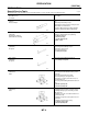
PREPARATION [RS5F70A] PREPARATION Special Service Tools PFP:00002 ECS005TE The actual shapes of the Kent-Moore tools may differ from those of the special service tools illustrated here. Tool number (Kent-Moore No.) Description Tool name KV38107700 (J39027) Preload adapter Measuring turning torque of final drive assembly Measuring total turning torque Measuring clearance between side gear and differential case with washer Selecting differential side bearing adjusting shim [Use with KV38106000 (J34291-B).
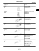
PREPARATION [RS5F70A] Tool number (Kent-Moore No.) Tool name Description A ST33061000 (J8107-2) Drift Removing differential side bearing a: 39 mm (1.54 in) dia. b: 29.5 mm (1.16 in) dia. B MT NT073 ST33290001 (J34286) Puller ● Removing idler gear bearing outer race D a: 250 mm (9.84 in) b: 160 mm (6.30 in) E NT414 ST33230000 (J25805-01) Drift Removing differential oil seal Installing differential side bearing a: 51 mm (2.01 in) dia. b: 28.5 mm (1.122 in) dia.
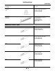
PREPARATION [RS5F70A] Tool number (Kent-Moore No.) Tool name Description ST30621000 (J35869) Drift Installing differential side bearing outer race [Use with ST30611000 (J25742-1).] a: 79 mm (3.11 in) dia. b: 59 mm (2.32 in) dia. NT073 ST30611000 (J25742-1) Drift handle Installing differential side bearing outer race [Use with ST30621000 (J35869).] a: 15 mm (0.59 in) b: 335 mm (13.19 in) c: 25 mm (0.98 in) dia. d: M12 × 1.
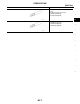
PREPARATION [RS5F70A] Tool name Description Drift Installing 3rd & 4th and 1st & 2nd synchronizer hub Installing mainshaft front bearing a: 50 mm (1.97 in) dia. b: 41 mm (1.61 in) dia. B MT NT065 Drift A Installing input shaft oil seal Installing 5th input gear a: 39 mm (1.54 in) dia. b: 30 mm (1.18 in) dia.
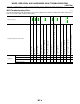
NOISE, VIBRATION, AND HARSHNESS (NVH) TROUBLESHOOTING [RS5F70A] NOISE, VIBRATION, AND HARSHNESS (NVH) TROUBLESHOOTING NVH Troubleshooting Chart PFP:00003 ECS005TG 3 1 Hard to shift or will not shift 1 1 2 Jumps out of gear MT-19, MT-21 MT-20 Bearing (Worn or damaged) 3 3 2 2 1 MT-8 Shift Fork (Worn) Control Rod (Worn) O-Ring (Worn or damaged) Oil Seal (Worn or damaged) 2 3 Insert Spring, Shifting Insert (Damaged) Oil leakage 3 Baulk Ring (Worn or damaged) Symptom Gear (Worn or dam
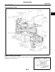
DESCRIPTION [RS5F70A] DESCRIPTION Cross-sectional View PFP:00000 A ECS005TH B MT D E F G H I J K L M WCIA0017E DOUBLE-CONE SYNCHRONIZER Double-cone synchronizer is used for 1st and 2nd gears to reduce operating force of the shift lever.
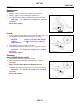
M/T OIL [RS5F70A] M/T OIL Replacement PFP:KLD20 ECS005TI DRAINING 1. 2. 3. Start the engine and let it run to warm up the transaxle. Stop the engine. Remove drain plug and drain oil. Set a gasket on the drain plug and install it on the transaxle. Drain plug : 10 - 19 N·m (1.0 - 2.0 kg-m, 87 - 173 in-lb) CAUTION: Do not reuse gasket. SMA145AA FILLING 1. Remove filler plug. Fill with new oil until oil level reaches the specified limit near filler plug mounting hole as shown.
SIDE OIL SEAL [RS5F70A] SIDE OIL SEAL Removal and Installation 1. 2. 3. PFP:32113 A ECS005TK Remove drain plug and drain the oil from transaxle. Refer to MT-10, "DRAINING" . Remove drive shafts. Refer to FAX-14, "Removal" . Remove differential oil seal using Tool. B MT D E SMT563A 4. Install differential oil seal with a suitable tool (drift). ● Apply multi-purpose grease to seal lip of oil seal before installing. F G H SMT126DB 5. Install drive shafts. Refer to FAX-16, "Installation" .
POSITION SWITCH [RS5F70A] POSITION SWITCH Position Switch Check PFP:32005 ECS005TL NOTE: For removal and installation of the switches. Refer to MT-18, "CASE COMPONENTS" . BACK-UP LAMP SWITCH ● Check continuity. Gear position Continuity Reverse Yes Except reverse No SMT715BD PNP SWITCH ● Check continuity.
CONTROL LINKAGE [RS5F70A] CONTROL LINKAGE Removal and Installation PFP:34103 A ECS005TM TRANSAXLE GEAR CONTROL Refer to the illustration for the removal and installation procedure. B MT D E F G H I J K L M WCIA0135E 1. Control lever knob 2. Boot 3. Finisher 4. Control lever bracket 5. Socket 6. Control lever 7. O-ring 8. O-ring 9. Ring spring 10. Bearing seat 11. Ring spring 12. Seat 13. Return spring 14. Control rod 15. Bushing 16. Collar 17. Bushing 18.
CONTROL LINKAGE [RS5F70A] STRIKING ROD OIL SEAL 1. 2. Remove the transaxle control rod from yoke. Remove the retaining pin from the yoke using Tool as shown. CAUTION: Be careful not to damage the boot. SMT143DB 3. 4. Remove the boot. Remove the striking rod oil seal with a suitable tool (drift). SMT566A 5. Install the striking rod oil seal using Tool as shown. ● Apply multi-purpose grease to the seal lip of the oil seal before installing. SMT570AA 6. 7. 8. Install the boot.
TRANSAXLE ASSEMBLY [RS5F70A] TRANSAXLE ASSEMBLY Removal and Installation PFP:32010 A ECS005TN B MT D E F WMT009 G REMOVAL 1. 2. Disconnect the negative battery terminal. Remove the air cleaner and air duct. Refer to EM-13, "Removal and Installation" . H I J K WMT010 3. Disconnect the clutch operating cylinder from the transaxle and position aside. Refer to CL-11, "Removal" . L M WCIA0006E 4. 5. Disconnect back-up lamp switch, VSS sensor, PNP switch, and ground harness connectors.
TRANSAXLE ASSEMBLY [RS5F70A] 6. Remove the air breather hose. SMT132D 7. Remove the shift control rod and support rod from transaxle. WMT005 8. Remove the drain plug and drain the gear oil from the transaxle. SMA145AA 9. Remove the drive shafts from the transaxle. Refer to FAX-14, "Removal" . 10. Support the engine by placing a jack under the oil pan as shown. CAUTION: Do not place the jack under the oil pan drain plug.
TRANSAXLE ASSEMBLY [RS5F70A] 11. Remove LH side and rear side mounting bolts. A B MT D E F G WMT007 12. Remove the lower housing bolts. H I J SMT658B K 13. Remove the bolts securing the transaxle to the engine. 14. Lower the transaxle while supporting it with the jack. L INSTALLATION Installation is in the reverse order of removal. ● Tighten the starter motor bolts to specification. Starter motor bolts ● ● M : 31 - 42 N·m (3.2 - 4.
TRANSAXLE ASSEMBLY [RS5F70A] Component Parts ECS005TO CASE COMPONENTS WMT014 1. Clutch housing 2. Dust seal 3. Oil pocket 4. Check plug 5. Input shaft oil seal 6. Oil channel 7. Mainshaft front bearing 8. Bearing retainer 9. Reverse idler gear front thrust washer 10. Reverse idler gear 11. Reverse idler gear bearing 12. Reverse idler gear rear thrust washer 13. O-ring 14. Reverse idler gear shaft 15. Snap ring 16. Back-up lamp switch 17. Filler plug 18.
TRANSAXLE ASSEMBLY [RS5F70A] GEAR COMPONENTS A B MT D E F G H SMT641DA 1. Reverse idler gear front thrust washer 2. Reverse idler gear 3. Reverse idler gear bearing 4. Reverse idler gear rear thrust washer 5. O-ring 6. Reverse idler gear shaft 7. Snap ring 8. Input shaft front bearing 9. Input shaft 10. 3rd gear needle bearing 11. 3rd input gear 12. 3rd gear baulk ring 13. Coupling sleeve 14. Spread spring 15. Shifting insert 16. 3rd & 4th synchronizer hub 17.
TRANSAXLE ASSEMBLY [RS5F70A] SHIFT CONTROL COMPONENTS WMT015 1. Clutch housing 2. 3rd & 4th bracket 3. 3rd & 4th shift fork 4. Retaining pin 5. Check ball 6. Check pin 7. Check spring 8. Check plug 9. Stopper ring 10. 3rd & 4th fork rod 11. Selector shaft pin 12. Selector 13. 5th & reverse bracket 14. Reverse switch bracket 15. Retaining pin 16. 5th & reverse shift fork 17. Interlock plunger 18. Check ball 19. Interlock pin 20. Stopper ring 21. 5th & reverse fork rod 22.
TRANSAXLE ASSEMBLY [RS5F70A] FINAL DRIVE COMPONENTS A B MT D E F G H I J WCIA0003E 1. Differential side bearing adjusting shim 2. Differential side bearing outer race 3. Differential side bearing 4. Final gear 5. Differential case 6. Speedometer drive gear 7. Speedometer stopper 8. Differential side bearing 9. Differential side bearing outer race 10. Pinion mate thrust washer 11. Pinion mate gear 12. Side gear thrust washer 13. Side gear 14. Pinion mate shaft 15.
TRANSAXLE ASSEMBLY [RS5F70A] 2. 3. Remove snap ring from reverse idler shaft as shown. Remove side cover and rear cover from case. SMT644D 4. 5. a. b. Remove O-ring and mainshaft bearing adjusting shim. Remove reverse idler gear shaft. Attach bolt (M6) to thread of reverse idler gear shaft end as shown. Pull out the attached bolt (M6), and remove reverse idler gear shaft from case. SMT645D 6. 7. Remove reverse idler gear, thrust washer (front and rear), and bearing from case.
TRANSAXLE ASSEMBLY [RS5F70A] 9. Remove transaxle case mounting bolts. A B MT SMT649D D 10. Remove input shaft rear bearing adjusting shim from transaxle case. 11. Remove oil gutter from transaxle case. E F G SMT650D H 12. Remove differential side bearing outer race and adjusting shim from transaxle case using Tool. I J K SMT651DA 13. Remove differential oil seal from transaxle case using Tool.
TRANSAXLE ASSEMBLY [RS5F70A] 14. Remove welch plugs from transaxle case using Tool. SMT839DA Clutch Housing 1. 2. Remove transaxle case from the clutch housing. Remove check plugs, check springs, check pins, and check balls from the clutch housing. SMT654D 3. Remove 3rd & 4th bracket retaining pin using Tool. SMT656DA 4. 5. 6. Remove 3rd & 4th shift fork stopper ring. Remove 3rd & 4th fork rod. Remove 3rd & 4th shift fork and bracket.
TRANSAXLE ASSEMBLY [RS5F70A] 7. 8. Remove interlock plunger and check ball. Remove 5th & reverse bracket stopper ring. A B MT SMT658D D 9. Remove retaining pins from 5th & reverse shift fork and 5th & reverse bracket using Tool. 10. Remove 5th & reverse fork rod. 11. Remove interlock pin from 5th & reverse fork rod using Tool. 12. Remove reverse switch bracket and 5th & reverse bracket. E F G SMT657DA 13. Remove check ball from housing. 14.
TRANSAXLE ASSEMBLY [RS5F70A] 20. Remove mainshaft bearing retainer from housing. 21. Cut off oil channel using a cutter as shown. SMT662D 22. Remove mainshaft front bearing from housing using Tool. SMT663DA 23. Using a magnet or other suitable tool, remove selector pin from selector shaft. SMT664D 24. Remove selector shaft and plug, then remove selector using Tool. SMT665DA 25.
TRANSAXLE ASSEMBLY [RS5F70A] 26. Remove retaining pin and plug from striking lever using Tool. 27. Remove striking rod, then striking lever from housing. A B MT SMT667DA 28. Using a flat-head screwdriver or other suitable tool, remove dust seal, input shaft oil seal, and striking rod oil seal from housing. CAUTION: When removing dust and oil seals, be careful not to damage mounting surfaces of dust seal and oil seal. D E F G SMT668D 29. Remove differential oil seal from housing using Tool.
TRANSAXLE ASSEMBLY [RS5F70A] ASSEMBLY Clutch Housing 1. Hammer the new striking rod oil seal into clutch housing as far as it will go using Tool. CAUTION: Do not reuse striking rod oil seal. SMT722DA 2. Hammer the differential oil seal into clutch housing with a suitable tool until it becomes flush with clutch housing end face. CAUTION: Do not reuse differential oil seal. SMT723DA 3. Hammer input shaft oil seal into clutch housing as far as it will go with a suitable tool.
TRANSAXLE ASSEMBLY [RS5F70A] 5. Install outer race of differential side bearing using Tool. A B MT SMT726DA D 6. Install new oil channel (mainshaft). CAUTION: Pay attention to installation direction of oil channel. E F G SMT727D 7. Align the notches on mainshaft front bearing and transaxle case. Then, install mainshaft front bearing with a suitable tool. H I J SMT728DA 8. K Install mainshaft bearing retainer, tighten bolt to specification. L M SMT729D 9.
TRANSAXLE ASSEMBLY [RS5F70A] 10. Hammer the new welch plug (striking lever side) with a generalpurpose drift [OD: 12 mm (0.47 in)]. CAUTION: Do not reuse welch plug. SMT730D 11. Install selector, selector shaft, and selector shaft pin into clutch housing. SMT731D 12. Hammer the new welch plug (selector shaft side) with a generalpurpose drift [OD: 12 mm (0.47 in)]. CAUTION: Do not reuse welch plug. SMT732D 13.
TRANSAXLE ASSEMBLY [RS5F70A] 15. Install oil pocket. A B MT SMT735D 16. Install differential assembly, input shaft assembly, and mainshaft assembly into clutch housing. CAUTION: Be careful not to damage input shaft oil seal during installation of input shaft assembly. D E F G SMT736D 17. Install 5th & reverse shift fork. 18. Install 1st & 2nd shift fork, bracket, and fork rod. 19. Install retaining pin for 1st & 2nd bracket using Tool. CAUTION: Do not reuse retaining pin. 20.
TRANSAXLE ASSEMBLY [RS5F70A] 26. Install 3rd & 4th shift fork, bracket, and fork rod. 27. Install 3rd & 4th bracket retaining pin using Tool. CAUTION: Do not reuse retaining pin. SMT656DB 28. Install 3rd & 4th shift fork stopper ring. CAUTION: Do not reuse stopper ring. 29. Install check ball, check pin, and check spring, and apply Anaerobic Liquid Gasket or equivalent onto the check plug. Then, tighten the check plug to specification. Refer to MT-20, "SHIFT CONTROL COMPONENTS" .
TRANSAXLE ASSEMBLY [RS5F70A] 3. Calculate dimension “N” (thickness of adjusting shim) using the following procedure to satisfy specification of end play for differential side bearing. End play : 0.15 - 0.21 mm (0.0059 - 0.
TRANSAXLE ASSEMBLY [RS5F70A] 5. Measure the turning torque of the final drive assembly using Tool. Turning torque of final drive assembly (New bearing) ● ● ● 6. : 2.9 - 6.9 N-m (30 - 70 kg-cm, 26 - 61 in-lb) When the old bearing is used again, turning torque will be slightly less than the above. Make sure turning torque is close to the specified range. Changes in turning torque of final drive assembly per revolution should be within 1.0 N-m (10 kg-cm, 8.7 in-lb) without binding.
TRANSAXLE ASSEMBLY [RS5F70A] 8. Install oil gutter into transaxle case. A B MT SMT650D D 9. Clean mating surfaces of clutch housing and transaxle case. Check for cracks and damage, then apply sealant. Use Genuine Anaerobic Liquid Gasket or equivalent. Refer to GI-45, "Recommended Chemical Products and Sealants" . E F G SMT802D 10. Install transaxle case onto clutch housing, and tighten mounting bolts with specified torque. Transaxle case mounting bolts H : Refer to MT-18, "CASE COMPONENTS" .
TRANSAXLE ASSEMBLY [RS5F70A] 13. Install check springs and check balls. Apply sealant to the thread on the check plug, and install it. SMT749D 14. Calculate thickness “P” of the adjusting shim using the following procedure to satisfy the specification of the end play for the mainshaft rear bearing. End play : 0 - 0.06 mm (0 - 0.
TRANSAXLE ASSEMBLY [RS5F70A] 15. Using snap ring pliers and flat-head screwdriver as shown, install snap ring. CAUTION: Do not reuse snap ring. A B MT SMT646D D 16. Install selected mainshaft adjusting shim. 17. Install reverse idler gear, O-ring, thrust washers (front and rear), and bearing onto reverse idler shaft. E F G SMT753DA H 18. Install snap ring into transaxle case using snap ring pliers. CAUTION: ● Do not reuse snap ring. ● Do not reuse O-ring.
INPUT SHAFT AND GEARS [RS5F70A] INPUT SHAFT AND GEARS Disassembly 1. PFP:32200 ECS005TQ Before disassembly, measure the end plays of 3rd and 4th input gears with a suitable tool. Refer to MT-61, "Gear End Play" . ● If end play is not within specification, disassemble and check the parts. SMT759D 2. Remove oil channel from input shaft rear bearing. SMT671D 3. Press out input shaft rear bearing using Tool. SMT672DA 4. 5. Remove C-ring holder. Remove 5th gear rear C-ring.
INPUT SHAFT AND GEARS [RS5F70A] 6. 7. Remove 5th input gear from input shaft using Tool. Remove 5th gear front C-ring. A B MT SMT674DA D 8. Remove 4th input gear, baulk ring, 4th gear needle bearing, and 4th gear C-ring from input shaft. 9. Press out both 3rd & 4th synchronizer hub assembly and 3rd input gear from input shaft using Tool. 10. Remove 3rd gear needle bearing. E F G SMT675DA H 11. Press out input shaft front bearing from input shaft using Tool.
INPUT SHAFT AND GEARS [RS5F70A] SYNCHRONIZERS ● ● ● Check spline area of coupling sleeves, hubs and gears for wear or cracks. Check baulk rings for cracks or deformation. Check insert springs for wear or deformation. SMT637A ● If any crack, damage, or excessive wear is found on cam face of baulk ring or working face of insert, replace it. SMT867D ● Measure the movement (free play in dimension “L”) of 3rd & 4th coupling sleeve with the end fixed and the other end lifted as shown in the figure.
INPUT SHAFT AND GEARS [RS5F70A] BEARING A Make sure bearings roll freely and are free from noise, cracks, pitting or wear. B MT SMT148A Assembly 1. D ECS005TS Press on input shaft front bearing using Tool. E F G SMT696DA 2. 3. Install 3rd gear needle, 3rd input gear and 3rd gear baulk ring bearing to input shaft. Install spread spring, shifting insert, and 3rd & 4th synchronizer hub onto 3rd & 4th coupling sleeve.
INPUT SHAFT AND GEARS [RS5F70A] ● Install 3rd & 4th coupling sleeve with its chamfered surface facing the 4th input gear side. SMT699D 4. Position bearing replacer to the front side of input shaft front bearing. ● Align grooves of shifting insert and 3rd gear baulk ring. Then, press it onto 3rd & 4th synchronizer hub assembly using a drift. SMT698DA 5. 6. Install 4th gear C-ring onto input shaft using Tool.
INPUT SHAFT AND GEARS [RS5F70A] 10. Position 5th input gear as shown, to install it on input shaft. A B MT SMT703D D 11. Install 5th input gear using Tool as shown. CAUTION: Do not reuse 5th input gear. E F G SMT702DA 12. Install 5th gear rear C-ring onto input shaft using Tool. 13. Measure the end play of 5th input gear with a suitable tool, and check if it is within the allowable specification below. End play H : 0 - 0.06 mm (0 - 0.0024 in) I J K SMT704D 14.
INPUT SHAFT AND GEARS [RS5F70A] 17. Install oil channel onto input shaft. SMT671D 18. Measure gear end play as a final check. Refer to MT-61, "Gear End Play" .
MAINSHAFT AND GEARS [RS5F70A] MAINSHAFT AND GEARS Disassembly 1. PFP:32241 A ECS005TT Before disassembly, measure gear end play with a suitable tool. Refer to MT-61, "Gear End Play" . ● If end play is not within the specified limit, disassemble and check the parts. B MT D SMT760D 2. E Remove snap ring with a suitable tool. F G H SMT677D 3. Remove C-ring holder and mainshaft C-ring. I J K SMT678D 4. L Press out mainshaft rear bearing from mainshaft using Tool.
MAINSHAFT AND GEARS [RS5F70A] 5. Remove mainshaft thrust washer. SMT680D 6. 7. Remove snap ring from mainshaft. Then, remove reverse main gear assembly, reverse gear needle bearing, and reverse gear baulk ring. Place bearing replacer between 5th & reverse synchronizer hub and 5th main gear, and press out both reverse gear bushing and 5th & reverse synchronizer assembly using Tool. WMT024 8. 9. Remove 5th main gear, 5th gear baulk ring, and 5th gear needle bearing.
MAINSHAFT AND GEARS [RS5F70A] 13. Place bearing replacer on 1st gear front side, and press out all of 2nd gear bushing, 1st & 2nd synchronizer hub, 1st main gear, and 1st double cone using Tool. A B MT WMT026 D 14. Remove 1st gear needle bearing. Inspection ECS005TU E GEAR AND SHAFT ● ● Check shaft for cracks, wear or bending. Check gears for excessive wear, chips or cracks. F G H SMT693D SYNCHRONIZERS ● ● ● I Check spline area of coupling sleeves, hubs and gears for wear or cracks.
MAINSHAFT AND GEARS [RS5F70A] ● Measure the movement (play, dimension “L”) of 1st & 2nd coupling sleeve and 5th & reverse coupling sleeve with their end fixed and the other end lifted as shown in the figure. If the movement exceeds specification, replace the sleeve. Coupling sleeve Length “L” 1st & 2nd 0 - 0.68 mm (0 - 0.0268 in) 5th & Reverse 0 - 0.89 mm (0 - 0.0350 in) SMT868D ● Measure clearance between baulk ring and gear. Refer to MT61, "Clearance Between Baulk Ring and Gear" .
MAINSHAFT AND GEARS [RS5F70A] ● If dimension “A” or “B” is smaller than the wear limit, replace outer baulk ring, inner baulk ring and synchronizer cone as a set. Assembly 1. A ECS005TV Install 1st gear needle bearing and 1st main gear onto mainshaft. B MT D SMT706D 2. 3. Install 1st double cone assembly onto mainshaft. Install 1st & 2nd synchronizer hub with its three grooves facing the front side (1st main gear side) onto mainshaft. CAUTION: Do not reuse 1st & 2nd synchronizer hub.
MAINSHAFT AND GEARS [RS5F70A] 6. Install 1st & 2nd coupling sleeve with its chamfered surface facing the 1st main gear side onto 1st & 2nd synchronizer hub. SMT708D 7. Install 2nd gear bushing with its flange surface facing 1st & 2nd synchronizer hub side using Tool. WMT027 8. 9. Install 2nd needle bearing, 2nd double cone assembly, and 2nd main gear onto mainshaft using Tool. Position 3rd main gear as shown, and install it using Tool. CAUTION: Do not reuse 3rd main gear. SMT710DA 10.
MAINSHAFT AND GEARS [RS5F70A] 12. Position 4th main gear as shown, and install it onto mainshaft. A B MT SMT713D D 13. Install 4th main gear onto mainshaft using Tool. CAUTION: Do not reuse 4th main gear. E F G SMT712DA 14. Install 5th gear bushing with its flange surface facing the 4th main gear side using Tool. H I J WMT028 K 15. Install 5th needle bearing, 5th main gear, and 5th gear baulk ring onto mainshaft. L M SMT761D 16.
MAINSHAFT AND GEARS [RS5F70A] ● ● Pay attention to the shape of spread spring and shifting insert for correct assembly. Do not install spread spring hook onto the same shifting insert. Install synchronizer hub with its three grooves facing the front side (5th main gear side). CAUTION: Do not reuse 5th & reverse synchronizer hub. SMT695D ● Install 5th & reverse coupling sleeve with its chamfered surface facing the reverse main gear side. SMT716D 17.
MAINSHAFT AND GEARS [RS5F70A] 22. Install reverse main gear assembly onto mainshaft. 23. Select a thrust washer suitable to satisfy the following specification of dimension “M” as shown, and install it onto mainshaft. Dimension “M” Available thrust washers A : 244.20 - 244.30 mm (9.6142 - 9.6181 in) : Refer to MT-64, "Available Thrust Washer" . B MT D E F G SMT719D 24. Install mainshaft rear bearing using Tool. H I J SMT720DA 25. Install mainshaft C-ring. 26.
MAINSHAFT AND GEARS [RS5F70A] 28. Install snap ring with a suitable tool. SMT677D 29. Measure gear end play as a final check. Refer to MT-61, "Gear End Play" .
FINAL DRIVE [RS5F70A] FINAL DRIVE Pre-inspection PFP:38411 A ECS005TW DIFFERENTIAL CASE SIDE 1. 2. 3. Clean final drive assembly sufficiently to prevent side gear thrust washer, differential case, side gear, and B other parts from sticking by gear oil. Upright the differential case so that the side gear to be measured faces upward. MT Place final drive adapter and dial gauge onto side gear. Move side gear up and down, and measure the clearance using Tool. Side gear and differential case clearance : 0.
FINAL DRIVE [RS5F70A] 7. 8. Remove pinion mate shaft. Rotate pinion mate gear, and remove pinion mate gear, pinion mate thrust washer, side gear, and side gear thrust washer from differential case. SMT839 Inspection ECS005TY GEAR, WASHER, SHAFT AND CASE ● ● Check mating surfaces of differential case, side gears and pinion mate gears. Check washers for wear. WCIA0004E BEARING ● Make sure bearings roll freely and are free from noise, cracks, pitting or wear.
FINAL DRIVE [RS5F70A] 4. Insert pinion mate shaft into differential case. A B MT SMT087A D 5. 6. 7. Upright the differential case so that its side gear to be measured faces upward. Place preload adapter and dial gauge onto side gear. Move side gear up and down, and measure the clearance using Tool. Turn differential case upside down, and measure the clearance between side gear and differential case on the other side in the same way using Tool.
FINAL DRIVE [RS5F70A] 11. Install differential side bearing using Tool. 12. Turn differential case upside down, and install another differential side bearing on the other side in the same way using Tool. SMT751DA 13. Install differential gear into differential case. Apply sealant onto mounting bolts, and tighten them in order as shown in the figure with specified torque. Differential gear mounting bolts : Refer to MT-21, "FINAL DRIVE COMPONENTS" .
SHIFT CONTROL [RS5F70A] SHIFT CONTROL Inspection ● PFP:32982 A ECS005U0 Check if the width of shift fork hook (sliding area with coupling sleeve) is within allowable specification below. Item One-side wear Sliding width of new part 1st & 2nd 0.2 mm (0.008 in) 7.80 - 7.93 mm (0.3071 - 0.3122 in) 3rd & 4th 0.2 mm (0.008 in) 7.80 - 7.93 mm (0.3071 - 0.3122 in) 5th & reverse 0.2 mm (0.008 in) 7.80 - 7.93 mm (0.3071 - 0.
SERVICE DATA AND SPECIFICATIONS (SDS) [RS5F70A] SERVICE DATA AND SPECIFICATIONS (SDS) General Specifications PFP:00030 ECS005U1 TRANSAXLE Engine QG18DE Transaxle model RS5F70A Number of speeds 5 Synchromesh type Warner Shift pattern Gear ratio 1st 3.333 2nd 1.955 3rd 1.286 4th 0.926 5th 0.756 Reverse Number of teeth Input gear Main gear 3.214 1st 15 2nd 22 3rd 28 4th 41 5th 45 Rev. 14 1st 50 2nd 43 3rd 36 4th 38 5th 34 Rev.
SERVICE DATA AND SPECIFICATIONS (SDS) [RS5F70A] Gear End Play ECS005U2 Unit: mm (in) Gear A End play 1st main gear B 2nd main gear 5th main gear 0.18 - 0.31 (0.0071 - 0.0122) MT Reverse main gear 3rd input gear 4th input gear 0.17 - 0.44 (0.0067 - 0.0173) D Clearance Between Baulk Ring and Gear ECS005U3 3RD, 4TH, 5TH, REVERSE BAULK RING Unit: mm (in) Gear Standard E Wear limit 3rd 4th F 0.90 - 1.45 (0.0354 - 0.0571) 0.7 (0.028) 5th Reverse 0.9 - 1.35 (0.0354 - 0.
SERVICE DATA AND SPECIFICATIONS (SDS) [RS5F70A] 3.00 mm (0.1181 in) 32205-6J000 3.03 mm (0.1193 in) 32205-6J001 3.06 mm (0.1205 in) 32205-6J002 3.09 mm (0.1217 in) 32205-6J003 3.12 mm (0.1228 in) 32205-6J004 *: Always check with the parts department for the latest information. 5TH INPUT GEAR REAR C-RING End play 0 - 0.06 mm (0 - 0.0024 in) Thickness Part number* 2.59 mm (0.1020 in) 32205-6J005 2.62 mm (0.1031 in) 32205-6J006 2.65 mm (0.1043 in) 32205-6J007 2.68 mm (0.
SERVICE DATA AND SPECIFICATIONS (SDS) [RS5F70A] 0.90 mm (0.0354 in) 32225-6J007 0.94 mm (0.0370 in) 32225-6J008 0.98 mm (0.0386 in) 32225-6J009 1.02 mm (0.0402 in) 32225-6J010 1.06 mm (0.0417 in) 32225-6J011 1.10 mm (0.0433 in) 32225-6J012 1.14 mm (0.0449 in) 32225-6J013 1.18 mm (0.0465 in) 32225-6J014 1.22 mm (0.0480 in) 32225-6J015 1.26 mm (0.0496 in) 32225-6J016 1.30 mm (0.0512 in) 32225-6J017 1.34 mm (0.0528 in) 32225-6J018 1.38 mm (0.0543 in) 32225-6J019 1.42 mm (0.
SERVICE DATA AND SPECIFICATIONS (SDS) [RS5F70A] 3.07 mm (0.1209 in) 32238-6J012 3.11 mm (0.1224 in) 32238-6J013 3.15 mm (0.1240 in) 32238-6J014 3.19 mm (0.1256 in) 32238-6J015 3.23 mm (0.1272 in) 32238-6J016 3.27 mm (0.1287 in) 32238-6J017 3.31 mm (0.1303 in) 32238-6J018 3.35 mm (0.1319 in) 32238-6J019 3.39 mm (0.1335 in) 32238-6J020 3.43 mm (0.1350 in) 32238-6J021 3.47 mm (0.1366 in) 32238-6J022 3.51 mm (0.
SERVICE DATA AND SPECIFICATIONS (SDS) [RS5F70A] Available Shims — Differential Side Bearing Preload and Adjusting Shim ECS005U9 A BEARING PRELOAD Unit: mm (in) Differential side bearing preload T* 0.15 - 0.21 (0.0059 - 0.0083) B * Install shims which are “deflection of differential case” + “T” in thickness. DIFFERENTIAL SIDE BEARING ADJUSTING SHIMS Thickness mm (in) Part number* 0.44 (0.0173) 38454-M8000 0.48 (0.0189) 38454-M8001 0.52 (0.0205) 38454-M8002 0.56 (0.0220) 38454-M8003 0.60 (0.
PRECAUTIONS [RS6F51H] PRECAUTIONS Caution ● ● ● ● ● ● PFP:00001 ECS005V2 Do not reuse transaxle oil, once it has been drained. Check oil level, and drain and refill transaxle oil with the vehicle on level ground. During removal or installation, keep inside of transaxle clean of dust and dirt. Check for the correct installation orientation prior to removal or disassembly. If mating marks are required, be certain they do not interfere with the function of the parts they are applied to.
PREPARATION [RS6F51H] PREPARATION Special Service Tools PFP:00002 A ECS005V3 The actual shapes of the Kent-Moore tools may differ from those of the special tools illustrated here. B Tool number (Kent-Moore No.
PREPARATION [RS6F51H] Tool number (Kent-Moore No.) Tool name Description KV40105020 ( — ) Drift 5th input gear and synchronizer hub removal 3rd main gear, 2nd main gear, 2nd bushing, 1st-2nd synchronizer hub, 1st main gear, reverse main gear and 1st bushing removal a: 39.7 mm (1.563 in) dia. b: 35 mm (1.38 in) dia. c: 15 mm (0.
PREPARATION [RS6F51H] Tool number (Kent-Moore No.) Tool name Description A KV40101630 (J35870) Drift Reverse main gear installation a: 68 mm (2.68 in) dia. b: 60 mm (2.36 in) dia. B MT ZZA1003D KV38102510 ( — ) Drift 1st bushing installation 1st-2nd synchronizer hub installation Differential side bearing installation a: 71 mm (2.80 in) dia. b: 65 mm (2.56 in) dia.
NOISE, VIBRATION, AND HARSHNESS (NVH) TROUBLESHOOTING [RS6F51H] NOISE, VIBRATION, AND HARSHNESS (NVH) TROUBLESHOOTING NVH Troubleshooting Chart PFP:00003 ECS005V5 3 1 Hard to shift or will not shift 1 1 2 Jumps out of gear MT-102, MT-109 Gear (Worn or damaged) Bearing (Worn or damaged) MT-121 Shift fork (Worn) 3 3 3 2 2 1 MT-70 Check plug return spring and check ball (Worn or damaged) MT-76 O-Ring (Worn or damaged) Oil seal (Worn or damaged) 2 3 Insert spring, shifting insert (Damaged)
DESCRIPTION [RS6F51H] DESCRIPTION Cross-sectional View PFP:00000 A ECS005V6 RS6F51H B MT D E F G H I J K L M WCIA0364E MT-71
DESCRIPTION [RS6F51H] 1. Input shaft rear bearing 2. 6th input gear 3. 5th & 6th synchronizer 4. 5th input gear 5. 4th input gear 6. 3rd & 4th synchronizer 7. 3rd input gear 8. Reverse idler gear (rear) 9. Reverse synchronizer 10. Reverse idler gear (front) 11. Reverse idler shaft 12. Clutch housing 13. Input shaft front bearing 14. Input shaft 15. Mainshaft 16. Mainshaft front bearing 17. Speedometer drive gear 18. Differential side bearing (front) 19. Final gear 20.
M/T OIL [RS6F51H] M/T OIL Replacement PFP:KLD20 A ECS005V7 DRAINING 1. 2. 3. Start the engine and let it run to warm up the transaxle oil. Stop the engine. Remove drain plug and drain oil. Set a new gasket on the drain plug and install it in transaxle body. Drain plug B MT : 30 - 39 N·m (3.1 - 4.0 kg-m, 23 - 28 ft-lb) CAUTION: Do not reuse gasket. D E WCIA0022E FILLING 1. Oil grade Capacity (approximately) 2. F Remove filler plug.
SIDE OIL SEAL [RS6F51H] SIDE OIL SEAL Removal and Installation PFP:32113 ECS005V9 REMOVAL 1. 2. Remove the drive shaft from the transaxle body. Refer to FAX-14, "Removal" . Remove oil seal with a slotted screwdriver. CAUTION: Be careful not to damage the case surface when removing the oil seal. WCIA0023E INSTALLATION Installation is in the reverse order of removal. ● Using Tool (drift), drive the new oil seal straight until it protrudes from the case end equal to dimension "A" as shown.
POSITION SWITCH [RS6F51H] POSITION SWITCH Checking PFP:32005 A ECS005VA NOTE: For removal and installation of the switches. Refer to MT-81, "Component Parts" . B BACK-UP LAMP SWITCH ● Check continuity. MT Gear position Continuity Reverse Yes Except reverse No D E SCIA0708E F PARK/NEUTRAL POSITION SWITCH ● Check continuity.
CONTROL LINKAGE [RS6F51H] CONTROL LINKAGE Removal and Installation of Control Device and Cable PFP:34103 ECS006H6 WCIA0136E 1. Snap pin 2. Washer 3. Cable 4. Manual lever 5. Shift cable 6. Lock plate 7. Control device assembly 8. Lock plate 9. Select cable 10. Shift cable 11. Control lever knob MT-76 12.
CONTROL LINKAGE [RS6F51H] 13. Control device assembly 14. Cover 15. Select cable 16. Floor 17. Pin 18. Shift cable 19. Washer 20. Clutch housing 21. Cable mounting bracket 22. Select cable 23. Shift cable 24. Lock plate A B 25. Lock plate CAUTION: ● Note that the select side lock plate for securing the control cable is different from the one on the MT shift side. ● After assembly, make sure selector lever automatically returns to Neutral when it is moved to 1st, 2nd, or Reverse.
AIR BREATHER HOSE [RS6F51H] AIR BREATHER HOSE Removal and Installation PFP:31098 ECS005VC LCIA0033E CAUTION: ● Make sure there are no pinched or restricted areas on the air breather hose caused by bending or winding when installing it. ● Insert the air breather hose into the transaxle tube until the overlap area reaches the spool.
TRANSAXLE ASSEMBLY [RS6F51H] TRANSAXLE ASSEMBLY Removal and Installation PFP:32010 A ECS005VD B MT D E F G H I WCIA0109E REMOVAL J 1. 2. 3. 4. K 5. 6. 7. 8. 9. 10. 11. 12. 13. 14. Remove the air cleaner and air duct. Remove the battery. Remove the air breather hose. Remove the clutch operating cylinder. CAUTION: Do not depress the clutch pedal during the removal procedure. Remove the engine under cover. Disconnect the control cable from the transaxle.
TRANSAXLE ASSEMBLY [RS6F51H] 15. Remove the bolts that mount the engine to the transaxle. 16. Remove the transaxle from the vehicle as shown. MTD0062D INSTALLATION Installation is the reverse order of removal. ● When installing the transaxle to the engine, use them specified tightening torque in the numerical sequence as shown. CAUTION: When installing the transaxle, do not allow the transaxle input shaft to make contact with the clutch cover. Bolt No.
TRANSAXLE ASSEMBLY [RS6F51H] Component Parts ECS005VE A CASE AND HOUSING COMPONENTS B MT D E F G H I J K L M SCIA1062E 1. Clutch housing 2. Input shaft oil seal 3. Oil channel 4. Magnet 5. Differential oil seal 6. Ball pin 7. Washer Welch plug 8. Transaxle case 9. 10. Bore plug 11. Differential oil seal 12. Park/Neutral position switch 13. Oil gutter 14. Back-up lamp switch 15. Air breather tube 16. Baffle plate 17. Filler plug 18. Gasket 19. Drain plug 20.
TRANSAXLE ASSEMBLY [RS6F51H] GEAR COMPONENTS SCIA0956E 1. Input shaft front bearing 2. Input shaft 3. Needle bearing 4. 3rd input gear 5. 3rd baulk ring 6. Spread spring 7. 3rd & 4th shifting insert 8. 3rd & 4th synchronizer hub 9. 4th baulk ring 10. 3rd & 4th coupling sleeve 11. Bushing 12. Needle bearing 13. 4th input gear 14. Thrust washer 15. Bushing 16. Needle bearing 17. 5th input gear 18. 5th baulk ring 19. 5th & 6th shifting insert 20. 5th & 6th synchronizer hub 21.
TRANSAXLE ASSEMBLY [RS6F51H] A B MT D E F G H SCIA0957E 1. Mainshaft front bearing 2. Mainshaft bearing retainer 3. Mainshaft 4. Reverse main gear 5. 1st main gear 6. Bushing 7. Needle bearing 8. 1st inner baulk ring 9. 1st gear synchronizer cone 10. 1st outer baulk ring 11. Spread spring 12. 1st & 2nd shifting insert 13. 1st & 2nd synchronizer hub 14. 2nd outer baulk ring 15. 2nd gear synchronizer cone 16. 2nd inner baulk ring 17. 1st & 2nd coupling sleeve 18.
TRANSAXLE ASSEMBLY [RS6F51H] SHIFT CONTROL COMPONENTS SCIA0958E 1. Reverse shift fork 2. Shifter cap 3. Reverse fork rod 4. Reverse lever assembly 5. 5th & 6th bracket 6. 5th & 6th fork rod 7. 5th & 6th shift fork 8. Retaining pin 9. 3rd & 4th bracket 10. 3rd & 4th shift fork 11. 3rd & 4th fork rod 12. 1st & 2nd shift fork 13. 1st & 2nd bracket 14. 1st & 2nd fork rod 15. Shift check sleeve 16. Inter lock pin 17. Check ball 18. Shift check sleeve 19. Check spring 20.
TRANSAXLE ASSEMBLY [RS6F51H] FINAL DRIVE COMPONENTS A B MT D E F G H WCIA0207E 1. Differential side bearing outer race 2. Differential side bearing 3. Speedometer drive gear 4. Differential case 5. Final gear 6. Differential side bearing 7. Differential side bearing outer race 8. Differential side bearing adjusting shim Disassembly and Assembly J ECS005VF DISASSEMBLY 1. 2. 3. I K Remove the drain plug and filler plug.
TRANSAXLE ASSEMBLY [RS6F51H] 5. Remove the transaxle case bolts as shown. SCIA0983E 6. 7. 8. 9. Remove the bore plug. CAUTION: Be careful not to damage transaxle case. While spreading the snap ring of the mainshaft rear bearing located at bore plug hole, remove the transaxle case. Remove the oil gutter and baffle plate. Remove the snap ring, mainshaft rear bearing adjusting shim, and input shaft rear bearing adjusting shim from the transaxle case. 10.
TRANSAXLE ASSEMBLY [RS6F51H] 14. Remove the reverse check ball plug, reverse check spring, reverse shift check sleeve, and check ball. Discard the check ball plug. A CAUTION: ● Do not reuse the check ball plug. ● Do not drop the check ball. B 15. With the shift lever in 5th position, remove the bracket bolts from the reverse lever assembly as shown. Lift the reverse lever assembly to remove. MT CAUTION: Retain the shifter cap for installation. D E SCIA0960E 16.
TRANSAXLE ASSEMBLY [RS6F51H] 24. Remove the retaining pin of 3rd-4th bracket using pin punch. 25. Remove the stopper rings for 3rd-4th shift fork. SCIA0393E 26. Pull out the 3rd-4th fork rod and remove 3rd-4th shift fork and bracket. 27. Remove the shift check sleeve from the clutch housing. 28. Remove the retaining pin of 1st-2nd shift fork using a suitable pin punch. SCIA0394E 29. Pull out the 1st-2nd fork rod with bracket. 30. Remove the 1st-2nd shift fork. 31.
TRANSAXLE ASSEMBLY [RS6F51H] 35. Remove the differential oil seal (clutch housing side) using Tool as shown. A B MT SMT117E D 36. Remove the differential side bearing outer race (clutch housing side) using Tool as shown. E F G SMT116E 37. Remove the input shaft oil seal using a suitable tool as shown. CAUTION: Do not damage the clutch housing sealing surface. H I J SCIA0398E K ASSEMBLY 1. Install a new input shaft oil seal from the clutch housing end of the side, to the depth of 1.8 - 2.
TRANSAXLE ASSEMBLY [RS6F51H] 2. Install a new differential oil seal using Tool (drift) as shown. CAUTION: Oil seals are not reusable. SCIA1023E 3. Install the oil channel on the mainshaft side as shown. CAUTION: Position the oil channel with the orientation as shown, for installation. SCIA0986E 4. Install the mainshaft front bearing using Tool (drift) as shown. CAUTION: Position the mainshaft front bearing with the orientation as shown, for installation SCIA1024E 5.
TRANSAXLE ASSEMBLY [RS6F51H] 7. Install the final drive assembly into the clutch housing. A B MT SCIA0888E D 8. Install the input shaft assembly, mainshaft assembly, and reverse idler gear assembly into the clutch housing. CAUTION: Do not damage the input shaft oil seal. E F G SCIA0964E 9. Install the 1st-2nd fork rod bracket onto the 1st-2nd fork rod, and then install a new retaining pin as shown. CAUTION: Retaining pins are not reusable. H I J SCIA0889E 10.
TRANSAXLE ASSEMBLY [RS6F51H] 13. Install the new stopper rings onto the 3rd-4th shift fork. CAUTION: Stopper rings are not reusable. 14. Install a new retaining pin onto the 3rd-4th bracket. CAUTION: Retaining pins are not reusable. SCIA0393E 15. Install the 2 check balls. 16. Install the 5th-6th bracket, 5th-6th shift fork, and 5th-6th fork rod. 17. Install new stopper rings onto the 5th-6th bracket with interlock pin. CAUTION: Stopper rings are not reusable. SCIA0963E 18.
TRANSAXLE ASSEMBLY [RS6F51H] 24. Install the reverse lever assembly using the following steps: a. Install the shifter cap onto the reverse lever assembly cam, and then install them onto the reverse shift fork. CAUTION: Do not drop the shifter cap. b. While lifting the reverse shift fork, align the cam with the reverse bracket. A B MT D E SCIA0965E c. Tighten the bracket bolts to specification, and install the reverse lever assembly. Bracket bolts F : 11.8 - 15.6 N·m (1.2 - 1.
TRANSAXLE ASSEMBLY [RS6F51H] d. Using a snap ring of the mainshaft rear bearing temporarily, install the transaxle case over the clutch housing as shown. SCIA0892E e. f. Through the bore plug mounting hole, with the snap ring stretched, lift up the mainshaft assembly from the control assembly mounting hole. Securely install the snap ring onto the mainshaft rear bearing as shown. SCIA0893E g. Tighten the “A” bolts (gold) and new “B” bolts (black) to specification. “A” Bolt “B” Bolt : 50.0 - 53.
TRANSAXLE ASSEMBLY [RS6F51H] 30. Install a new bore plug using Tool (drift) as shown. CAUTION: Bore plugs are not reusable. A B MT SCIA1025E D 31. Install the new welch plug using Tool (drift). CAUTION: Do not reuse the welch plug E F G SMT131E 32. Install the 2 check balls, 2 check springs, and 2 new check ball plugs. CAUTION: Check ball plugs are not reusable. H I J LCIA0302E 33. Apply sealant to the threads of the neutral switch and reverse lamp switch.
TRANSAXLE ASSEMBLY [RS6F51H] Adjustment ECS005VG INPUTSHAFT END PLAY When adjusting the input shaft end play, select the adjusting shim for the input shaft bearing. To select the correct thickness for the adjusting shim, measure the clearance between the transaxle case and input shaft rear bearing. Calculate the dimension “O” (thickness of adjusting shim) using the following steps to adjust the input shaft rear bearing for the specified end play.
TRANSAXLE ASSEMBLY [RS6F51H] 2. Using a depth micrometer and straight edge, measure the dimension “O2 ” between the clutch housing case end face and end face of the input shaft rear bearing as shown. A B MT SCIA1004E D 3. Install the selected input shaft rear bearing adjusting shim onto the input shaft. DIFFERENTIAL SIDE BEARING PRELOAD ● ● E When adjusting differential side bearing preload, select adjusting shim for differential side bearing.
TRANSAXLE ASSEMBLY [RS6F51H] 2. 3. Install the outer race onto the differential side bearing on the final gear side. Holding the outer race horizontally by hand, rotate the final gear five times or more (for smooth movement of the bearing roller). Using a depth micrometer and straight edge, measure the dimension “L2 ” between the differential side bearing outer race and transaxle case end face as shown. SCIA1079E 4.
TRANSAXLE ASSEMBLY [RS6F51H] Adjusting Shim Shim thickness Part number 0.44 mm (0.0173 in) 0.48 mm (0.0189 in) 0.52 mm (0.0205 in) 0.56 mm (0.0220 in) 0.60 mm (0.0236 in) 0.64 mm (0.0252 in) 0.68 mm (0.0268 in) 0.72 mm (0.0283 in) 0.76 mm (0.0299 in) 0.80 mm (0.0315 in) 0.84 mm (0.0331 in) 0.88 mm (0.0346 in) 0.92 mm (0.0362 in) 0.96 mm (0.0378 in) 1.00 mm (0.0396 in) 1.04 mm (0.0409 in) 1.08 mm (0.
TRANSAXLE ASSEMBLY [RS6F51H] Adjusting Shim 1. Shim thickness Part number 1.76 mm (0.0693 in) 1.84 mm (0.0724 in) 1.92 mm (0.0756 in) 2.00 mm (0.0787 in) 2.08 mm (0.0819 in) 2.16 mm (0.0850 in) 2.24 mm (0.0882 in) 2.32 mm (0.0913 in) 2.40 mm (0.0945 in) 2.48 mm (0.0976 in) 2.56 mm (0.1008 in) 2.64 mm (0.
INPUT SHAFT AND GEARS [RS6F51H] INPUT SHAFT AND GEARS Disassembly and Assembly PFP:32200 A ECS005VH DISASSEMBLY 1. Before disassembling, measure the end play for 3rd, 4th, 5th, and 6th input gears. B End play standard values 3rd gear : 0.18 - 0.31 mm (0.0071 - 0.0122 in) 4th gear : 0.20 - 0.30 mm (0.0079 - 0.0118 in) 5th gear : 0.06 - 0.16 mm (0.0024 - 0.0063 in) 6th gear : 0.06 - 0.16 mm (0.0024 - 0.
INPUT SHAFT AND GEARS [RS6F51H] 9. Remove the 5th bushing, thrust washer, 4th input gear, 4th needle bearing, 4th bushing, 4th baulk ring, 3rd-4th synchronizer hub assembly, 3rd baulk ring, and 3rd input gear simultaneously using Tool as shown. 10. Remove the 3rd needle bearing. SCIA1030E 11. Remove the input shaft front bearing using Tool as shown. SCIA0920E INSPECTION AFTER DISASSEMBLY Input Shaft and Gear Inspect the components for the following conditions as shown.
INPUT SHAFT AND GEARS [RS6F51H] ● If any cracks, damage, or excessive wear is found on the cam face of baulk ring or working face of the insert as shown, replace it. A B MT SMT867D D Baulk ring clearance Press the baulk ring against cone, and measure clearance between baulk ring and cone. If measurement is below limit, replace it with a new one. E Clearance - standard 3rd and 4th : 0.9 - 1.45 mm (0.035 - 0.0571 in) 5th and 6th : 0.95 - 1.4 mm (0.0374 - 0.055 in) Limit : 0.7 mm (0.
INPUT SHAFT AND GEARS [RS6F51H] ● Install with orientation of coupling sleeve as shown. SCIA0993E ● Be sure not to hook the ends of the 2 spread springs (front and back have two each) on the same shifting insert. SCIA1083E 4. Install 3rd-4th coupling sleeve assembly using Tool as shown. CAUTION: Align the grooves of the shifting insert and the 3rd baulk ring. SCIA1031E 5. 6. 7. Install the 4th bushing using Tool as shown. Install the 4th baulk ring.
INPUT SHAFT AND GEARS [RS6F51H] 8. Measure the dimension “C2 ” as shown. Select a thrust washer so that dimension “C2 ” satisfies standard dimension specification. Then install the thrust washer onto the input shaft. Standard for dimension “C2 ” A : 154.7 - 154.8 mm (6.091 - 6.094 in) B CAUTION: Only 1 thrust washer can be selected. MT D E F G SCIA0925E Thrust Washer Thickness Part number Thickness Part number H 3.84 mm (0.1512 in) 3.90 mm (0.1535 in) 3.96 mm (0.
INPUT SHAFT AND GEARS [RS6F51H] ● Be sure not to hook the ends of the 2 spread springs (front and back have two each) on the same shifting insert. SCIA1083E 13. Install the 5th-6th synchronizer hub assembly using Tool as shown. CAUTION: Align the grooves of the 5th-6th shifting insert and 5th-6th baulk ring. SCIA1039E 14. Install the needle bearing, 6th input gear and then 6th bushing using Tool as shown. SCIA1040E 15.
INPUT SHAFT AND GEARS [RS6F51H] 16. Install the input shaft rear bearing using Tool as shown. CAUTION: Install input shaft rear bearing with its brown surface facing the input gear side. A B MT SCIA1041E D 17. Install the input shaft front bearing using Tool as shown. 18. Install the oil channel onto the input shaft. E F G SCIA1042E 19. Check the end play of the 3rd, 4th, 5th and 6th input gears as shown. H End play standard value 3rd gear : 0.18 - 0.31 mm (0.0071 - 0.0122 in) 4th gear : 0.20 - 0.
MAINSHAFT AND GEARS [RS6F51H] MAINSHAFT AND GEARS Disassembly and Assembly PFP:32241 ECS005VI DISASSEMBLY 1. Before disassembling, measure the end play of 1st and 2nd main gears as shown. End play standard value 1st gear : 0.20 - 0.30 mm (0.0079 - 0.0118 in) 2nd gear : 0.06 - 0.16 mm (0.0024 - 0.0063 in) CAUTION: If the measurement is outside the standard value, disassemble to check the contact surfaces of gear, shaft, and hub. Adjust with the snap ring at assembly. SCIA0973E 2. 3.
MAINSHAFT AND GEARS [RS6F51H] 9. Remove the 3rd main gear, 2nd main gear, 2nd gear needle bearing, 2nd bushing, 1st-2nd synchronizer assembly, 1st main gear, reverse main gear, 1st gear needle bearing, and 1st bushing simultaneously using Tool as shown. A B MT SCIA1045E D INSPECTION AFTER DISASSEMBLY Mainshaft and Gears Check the items listed as shown. If necessary, replace them with new ones. ● Damage, peeling, dent, uneven wear, bending, and other nonstandard conditions of the mainshaft.
MAINSHAFT AND GEARS [RS6F51H] Baulk Ring Clearance Double Cone Synchronizer (1st) Check the clearance of outer baulk ring, synchronizer cone, and inner baulk ring of 1st double cone synchronizer, using the following steps. NOTE: The mean value is the middle value of a set of measurements between the highest and lowest values. It is calculated by adding the highest and lowest measured value and dividing their sum by two: [(high value) + (low value)] / 2 = mean value.
MAINSHAFT AND GEARS [RS6F51H] 3. Press the baulk ring on to the clutch gear taper cone by hand, then measure the clearance “A” at two or more points diagonally opposite with a feeler gauge, and then calculate the mean value. A Clearance “A” Standard : 0.6 - 1.2 mm (0.024 - 0.047 in) Limit : 0.3 mm (0.012 in) B MT LCIA0298E 4. D Measure clearances “B” at two or more points diagonally opposite with a feeler gauge, and then calculate the mean value. Clearance “B” Standard : 0.6 - 1.1 mm (0.024 - 0.
MAINSHAFT AND GEARS [RS6F51H] ASSEMBLY 1. Install the reverse main gear using Tool as shown. SCIA1048E CAUTION: Install with the orientation of reverse main gear as shown. SCIA0992E 2. 3. Install the 1st bushing using Tool as shown. Install the needle bearing, and then the 1st main gear. SCIA1049E 4. Install the spread spring, shifting insert, and a new 1st-2nd synchronizer hub onto the 1st-2nd coupling sleeve.
MAINSHAFT AND GEARS [RS6F51H] ● Install with the orientation of coupling sleeve as shown. A B MT SCIA0989E D ● Do not hook the ends of the two spread springs (front and back have two each) on the same shifting insert. E F G SCIA1083E 5. Install the 1st-2nd coupling sleeve assembly onto the mainshaft, and the synchronizer hub assembly onto the mainshaft using Tool as shown. CAUTION: ● Outer baulk ring, synchronizer cone, and inner baulk ring on the 2nd gear-side must have been removed.
MAINSHAFT AND GEARS [RS6F51H] 11. Measure the dimension “C1 ”. Select a suitable adjusting shim so that the dimension “C1 ” satisfies the specified standard value, and install it onto the mainshaft. Standard for dimension “C1 ” : 173.85 - 173.95 mm (6.844 - 6.848 in) CAUTION: Only 1 adjusting shim can be selected. SCIA0944E Adjusting Shim Thickness Part number Thickness Part number 0.52 mm (0.0205 in) 0.60 mm (0.0236 in) 0.68 mm (0.0268 in) 0.76 mm (0.
MAINSHAFT AND GEARS [RS6F51H] 15. Install the 6th main gear using Tool as shown. A B MT SCIA1057E D 16. Select the 6th main adjusting shim and then install it onto the mainshaft. ● Calculate thickness “S” of 6th main adjusting shim by procedure below so that end play dimension between 6th main gear and mainshaft rear bearing becomes the dimension specified. E End play : 0 - 0.1 mm (0 - 0.
MAINSHAFT AND GEARS [RS6F51H] 18. Install the C-ring onto the mainshaft, and check that the end play of mainshaft rear bearing meets specifications. End play standard value ● : 0 - 0.06 mm (0 - 0.0024 in) If the measurement is outside the specified standard value, reselect a new C-ring. SCIA0979E C-Ring Thickness Part number Thickness Part number 2.535 mm (0.0866 in) 2.565 mm (0.1010 in) 2.595 mm (0.1022 in) 2.625 mm (0.1033 in) 2.655 mm (0.1045 in) 2.685 mm (0.1057 in) 2.715 mm (0.1069 in) 2.
REVERSE IDLER SHAFT AND GEARS [RS6F51H] REVERSE IDLER SHAFT AND GEARS Disassembly and Assembly PFP:32281 A ECS005VJ DISASSEMBLY 1. 2. 3. 4. 5. 6. 7. 8. 9. Remove the reverse idler gear adjusting shim. Remove the reverse idler gear (rear), reverse coupling sleeve and insert spring simultaneously. Remove the reverse idler gear needle bearing. Remove the thrust needle bearing. Remove the reverse baulk ring. Remove the reverse idler gear (front). Remove the reverse idler gear needle bearing.
REVERSE IDLER SHAFT AND GEARS [RS6F51H] Baulk ring clearance ● Press the baulk ring against the cone, and measure the clearance between the baulk ring and cone as shown. If the measurement is below the specified limit, replace it with a new one. Baulk ring to gear clearance Standard : 0.95 - 1.4 mm (0.0374 - 0.055 in) Limit value : 0.7 mm (0.028 in) SMT140 Bearing Check the parts listed. If necessary, replace them with new ones. ● Damage and rough rotation of the bearing.
FINAL DRIVE [RS6F51H] FINAL DRIVE Disassembly and Assembly PFP:38411 A ECS005VK DISASSEMBLY 1. 2. 3. Remove the mounting bolts. Then, separate the final gear from the differential case. Remove the speedometer drive gear. Using a puller and Tool (drift), remove the differential side bearing (clutch housing side) as shown. B MT D E SCIA1019E 4. F Using a puller and Tool (drift), remove the differential side bearing (transaxle case side) as shown.
FINAL DRIVE [RS6F51H] 2. Align and install the speedometer drive gear onto the differential case as shown. SMT842D 3. Using Tool (drift), install the differential side bearing (clutch housing side) as shown. SCIA1018E 4. Install the final gear into the differential case, and tighten the final gear bolts to specification. Final gear bolts : Refer to MT-85, "FINAL DRIVE COMPONENTS" .
SHIFT CONTROL [RS6F51H] SHIFT CONTROL Inspection PFP:32982 A ECS005VL Check the contact surfaces and sliding area for wear, damage, or bending as shown. If necessary, replace the parts. B MT D E F G H SCIA0913E SHIFT FORK Check if the width of the shift fork hook (sliding area with coupling sleeve) is within specification, as shown. I J K SMT801D L Shift Fork Item One-side wear specification Sliding width of new part 1st & 2nd 0.2 mm (0.008 in) 7.80 - 7.93 mm (0.3071 - 0.
SERVICE DATA AND SPECIFICATIONS (SDS) [RS6F51H] SERVICE DATA AND SPECIFICATIONS (SDS) General Specifications PFP:00030 ECS005VM TRANSAXLE Engine QR25DE Transaxle model RS6F51H Model code number 7Y076 Number of speed 6 Synchromesh type Warner Shift pattern SCIA0955E Gear ratio Number of teeth 1st 3.153 2nd 1.944 3rd 1.392 4th 1.055 5th 0.809 6th 0.630 Reverse 3.
SERVICE DATA AND SPECIFICATIONS (SDS) [RS6F51H] FINAL GEAR Engine QR25DE Transaxle model RS6F51H Model code number 7Y076 Final gear ratio 4.133 Number of teeth Final gear/Pinion A B 62/15 Side gear/Pinion mate gear MT — Gear End Play ECS005VN Unit: mm (in) Gear D End play 1st main gear 0.20 - 0.30 (0.0079 - 0.0118) 2nd main gear 0.06 - 0.16 (0.0024 - 0.0063) 3rd input gear 0.18 - 0.31 (0.0071 - 0.0122) 4th input gear 0.20 - 0.30 (0.0079 - 0.0118) 5th input gear 0.06 - 0.16 (0.
SERVICE DATA AND SPECIFICATIONS (SDS) [RS6F51H] 1ST AND 2ND BAULK RING Unit: mm (in) 1st Double Baulk Ring SMT138E 2nd Triple Baulk Ring WCIA0195E Standard Dimension Wear limit Double baulk ring Triple baulk ring Double baulk ring Triple baulk ring A 0.6 - 0.8 (0.024 - 0.031) 0.6 - 1.2 (0.024 - 0.047) 0.2 (0.008) 0.3 (0.012) B 0.6 - 1.1 (0.024 - 0.043) 0.6 - 1.1 (0.024 - 0.043) 0.2 (0.008) 0.2 (0.008) C — 0.7 - 1.1 (0.028 - 0.043) — 0.3 (0.
SERVICE DATA AND SPECIFICATIONS (SDS) [RS6F51H] Available Thrust Washers ECS005VR A INPUT SHAFT THRUST WASHER B MT D SCIA1008E Standard length “C2 ” Thickness 154.7 - 154.8 mm (6.091 - 6.094in) mm (in) Part number* 3.84 (0.1512) 3.90 (0.1535) 3.96 (0.1559) Thickness 32347 8H500 32347 8H501 32347 8H502 mm (in) E Part number* 4.02 (0.1583) 4.08 (0.1606) 4.14 (0.1630) 32347 8H503 32347 8H504 32347 8H505 F *: Always check with the Parts Department for the latest parts information.
SERVICE DATA AND SPECIFICATIONS (SDS) [RS6F51H] *: Always check with the Parts Department for the latest parts information. MAINSHAFT REAR BEARING ADJUSTING SHIM End play 0 - 0.06 mm (0 - 0.0024 in) Thickness mm (in) 0.44 (0.0173) 0.48 (0.0189) 0.52 (0.0205) 0.56 (0.0220) 0.60 (0.0236) 0.64 (0.0252) 0.68 (0.0268) 0.72 (0.0283) 0.76 (0.0299) Part number* Thickness 32238 8H510 32238 8H511 32238 8H512 32238 8H513 32238 8H514 32238 8H515 32238 8H516 32238 8H517 32238 8H518 mm (in) 0.80 (0.0315) 0.