J AIR CONDITIONER SECTION MTC MANUAL AIR CONDITIONER A B C D E CONTENTS PRECAUTIONS .......................................................... 4 Precautions for Supplemental Restraint System (SRS) “AIR BAG” and “SEAT BELT PRE-TENSIONER” .................................................................. 4 Precautions for Working with HFC-134a (R-134a)..... 4 Contaminated Refrigerant ........................................ 4 General Refrigerant Precautions ..............................
Operational Check .................................................. 40 CONDITIONS: ..................................................... 40 PROCEDURE: ..................................................... 40 Power Supply and Ground Circuit for Front Air Control ........................................................................... 42 COMPONENT DESCRIPTION ............................ 42 DIAGNOSTIC PROCEDURE .............................. 42 LAN System Circuit ..........................................
INSTALLATION ................................................... 98 Removal and Installation for High-pressure Flexible Hose ....................................................................... 98 REMOVAL ........................................................... 98 INSTALLATION ................................................... 98 Removal and Installation for High-pressure Pipe ... 98 REMOVAL ........................................................... 98 INSTALLATION ..................................
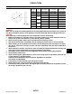
PRECAUTIONS PRECAUTIONS PFP:00001 Precautions for Supplemental Restraint System (SRS) “AIR BAG” and “SEAT BELT PRE-TENSIONER” EJS002RO The Supplemental Restraint System such as “AIR BAG” and “SEAT BELT PRE-TENSIONER”, used along with a front seat belt, helps to reduce the risk or severity of injury to the driver and front passenger for certain types of collision. This system includes seat belt switch inputs and dual stage front air bag modules.
PRECAUTIONS ● does not have dedicated recovery equipment, you may contact a local refrigerant product retailer for available service. This refrigerant must be disposed of in accordance with all federal and local regulations. In addition, replacement of all refrigerant system components on the vehicle is recommended. If the vehicle is within the warranty period, the air conditioner warranty is void. Please contact NISSAN Customer Affairs for further assistance.
PRECAUTIONS A/C Identification Label EJS002RT Vehicles with factory installed fluorescent dye have this green identification label on the underside of hood. WJIA0713E Precautions for Refrigerant Connection EJS002RU A new type refrigerant connection has been introduced to all refrigerant lines except the following locations.
PRECAUTIONS O-RING AND REFRIGERANT CONNECTION A QR25DE B C D E F G H I MTC K L M WJIA0981E Revision: March 2005 MTC-7 2005 Altima
PRECAUTIONS VQ35DE WJIA0982E CAUTION: The new and former refrigerant connections use different O-ring configurations. Do not confuse Orings since they are not interchangeable. If a wrong O-ring is installed, refrigerant will leak at, or around, the connection.
PRECAUTIONS O-Ring Part Numbers and Specifications O-ring size Part number* D New 8 92471 N8210 6.8 (0.268) 1.85 (0.0728) Former 10 J2476 89956 9.25 (0.3642) 1.78 (0.0701) 92472 N8210 10.9 (0.429) 2.43 (0.0957) 92475 71L00 11.0 (0.433) 2.4 (0.094) 92473 N8210 13.6 (0.535) 2.43 (0.0957) Former 92475 72L00 14.3 (0.563) 2.3 (0.091) New 92474 N8210 16.5 (0.650) 2.43 (0.0957) 92477 N8200 17.12 (0.6740) 1.78 (0.0701) 92195 AH300 21.8 (0.858) 2.4 (0.
PRECAUTIONS ● After connecting line, conduct leak test and make sure that there is no leakage from connections. When the gas leaking point is found, disconnect that line and replace the O-ring. Then tighten connections of seal seat to the specified torque. RHA861F Precautions for Servicing Compressor ● ● ● ● ● ● EJS002RV Plug all openings to prevent moisture and foreign matter from entering. When the compressor is removed, store it in the same position as it is when mounted on the car.
PRECAUTIONS VACUUM PUMP A The lubricant contained inside the vacuum pump is not compatible with the specified lubricant for HFC-134a (R-134a) A/C systems. The vent side of the vacuum pump is exposed to atmospheric pressure so the vacuum pump lubricant may migrate out of the pump into the service hose. This is possible when the pump is switched off after evacuation (vacuuming) and hose is connected to it. To prevent this migration, use a manual valve situated near the hose-to-pump connection, as follows.
PRECAUTIONS SERVICE COUPLERS Never attempt to connect HFC-134a (R-134a) service couplers to a CFC-12 (R-12) A/C system. The HFC-134a (R-134a) couplers will not properly connect to the CFC-12 (R-12) system. However, if an improper connection is attempted, discharging and contamination may occur.
PREPARATION PREPARATION Special Service Tools PFP:00002 A EJS003GJ The actual shapes of Kent-Moore tools may differ from those of special service tools illustrated here. Tool number (Kent-Moore No.
PREPARATION Tool number (Kent-Moore No.) Tool name Description — (J-41995) Electronic refrigerant leak detector Power supply: ● DC 12V (Battery terminal) AHA281A — (J-43926) Refrigerant dye leak detection kit Kit includes: (J-42220) UV lamp and UV safety goggles (J-41459) Refrigerant dye injector (J-41447) qty.
PREPARATION Tool number (Kent-Moore No.) Tool name Description — (J-39183-C) Manifold gauge set (with hoses and couplers) Identification: A ● The gauge face indicates R-134a.
PREPARATION Commercial Service Tools EJS003GL Tool number Tool name Description J-41810-NI Refrigerant identifier equipment HFC 134a (R-134a) Checking refrigerant purity and system contamination RJIA0197E Power tool Removing bolts and nuts PBIC0190E J-44614 Clutch disc holding tool Holding clutch disc for removal and installation WHA230 Revision: March 2005 MTC-16 2005 Altima
REFRIGERATION SYSTEM REFRIGERATION SYSTEM Refrigerant Cycle PFP:KA990 A EJS002S1 REFRIGERANT FLOW The refrigerant flows in the standard pattern, that is, through the compressor, the condenser with liquid tank, through the evaporator, and back to the compressor. The refrigerant evaporation through the evaporator coil is controlled by an externally equalized expansion valve, located inside the evaporator case.
REFRIGERATION SYSTEM Component Layout EJS002S3 WJIA0979E Revision: March 2005 MTC-18 2005 Altima
LUBRICANT LUBRICANT Maintenance of Lubricant Quantity in Compressor PFP:KLG00 A EJS002S4 The lubricant in the compressor circulates through the system with the refrigerant. Add lubricant to compressor when replacing any component or after a large refrigerant leakage has occurred. It is important to maintain the specified amount.
LUBRICANT 7. 8. 9. Measure an amount of new lubricant installed equal to amount drained from “old” compressor. Add this lubricant to “new” compressor through the suction port opening. Measure an amount of new lubricant equal to the amount recovered during discharging. Add this lubricant to “new” compressor through the suction port opening. If the liquid tank also needs to be replaced, add an additional 5 m (0.2 US fl oz, 0.2 Imp fl oz) of lubricant at this time. CAUTION: Do not add this 5 m (0.
AIR CONDITIONER CONTROL AIR CONDITIONER CONTROL Overview Air Conditioner LAN Control System PFP:27500 A EJS002S5 The LAN (local area network) system consists of front air control, air mix door motor, intake door motor, and mode door motor. A configuration of these components is shown in the diagram below. B C D E WJIA0876E System Construction EJS002S6 F A small network is constructed between the front air control, air mix door motor, intake door motor, and mode door motor.
AIR CONDITIONER CONTROL quently, HOT/COLD, DEFROST/VENT or FRESH/RECIRCULATION operation is selected. The new selection data is returned to the front air control. WJIA0878E TRANSMISSION DATA AND TRANSMISSION ORDER Front air control data is transmitted consecutively to each of the door motors following the form shown in figure below. Start: Initial compulsory signal sent to each of the door motors.
AIR CONDITIONER CONTROL FAN SPEED CONTROL A Blower speed is controlled by the front air control based on the position of the fan dial. With the fan dial set to any position except OFF, the blower will begin to operate. INTAKE DOOR CONTROL The intake door is controlled by the front air control based on input from the recirculation switch setting, and the MAX A/C switch setting. MODE DOOR CONTROL B C The mode door is controlled by the front air control based on input from the mode dial setting.
AIR CONDITIONER CONTROL The relationship of these components is shown in the diagram below: WJIA0905E Control Operation EJS002S8 WJIA0906E Revision: March 2005 MTC-24 2005 Altima
AIR CONDITIONER CONTROL AIR CONDITIONER (A/C) SWITCH The air conditioner switch controls the A/C system. When the switch is pressed with the fan ON, the compressor will turn ON. The indicator lamp will also illuminate. The air conditioner cooling function operates only when the engine is running. A TEMPERATURE DIAL (POTENTIO TEMPERATURE CONTROL) B Increases or decreases the set temperature. FAN DIAL/OFF SWITCH C Manually controls the blower speed.
AIR CONDITIONER CONTROL Discharge Air Flow EJS002S9 WJIA1185E Revision: March 2005 MTC-26 2005 Altima
AIR CONDITIONER CONTROL System Description EJS002SA A SWITCHES AND THEIR CONTROL FUNCTION B C D E F RHA044GA G H I MTC K L M WJIA0907E CAN Communication System Description EJS002SB Refer to LAN-21, "CAN COMMUNICATION" .
TROUBLE DIAGNOSIS TROUBLE DIAGNOSIS How to Perform Trouble Diagnoses for Quick and Accurate Repair PFP:00004 EJS002SC WORK FLOW SHA900E *1: MTC-40 SYMPTOM TABLE Reference Page Symptom ● A/C system does not come on. ● Go to Trouble Diagnosis Procedure for A/C system. MTC-42 ● Air outlet does not change. ● Mode door motor does not operate normally. ● Go to Trouble Diagnosis Procedure for Mode Door Motor. (LAN) MTC-47 ● Discharge air temperature does not change.
TROUBLE DIAGNOSIS Component Parts and Harness Connector Location EJS002SD A ENGINE COMPARTMENT QR25DE Models B C D E F G H I MTC K L M WJIA0136E Revision: March 2005 MTC-29 2005 Altima
TROUBLE DIAGNOSIS VQ35DE Model WJIA0137E Revision: March 2005 MTC-30 2005 Altima
TROUBLE DIAGNOSIS PASSENGER COMPARTMENT A B C D E F G H I MTC K L M WJIA1559E Revision: March 2005 MTC-31 2005 Altima
TROUBLE DIAGNOSIS Circuit Diagram EJS002SE WJWA0137E Revision: March 2005 MTC-32 2005 Altima
TROUBLE DIAGNOSIS Wiring Diagram — HEATER — EJS002SF A B C D E F G H I MTC K L M WJWA0138E Revision: March 2005 MTC-33 2005 Altima
TROUBLE DIAGNOSIS WJWA0275E Revision: March 2005 MTC-34 2005 Altima
TROUBLE DIAGNOSIS Wiring Diagram — A/C,M — EJS003GP A B C D E F G H I MTC K L M WJWA0140E Revision: March 2005 MTC-35 2005 Altima
TROUBLE DIAGNOSIS WJWA0177E Revision: March 2005 MTC-36 2005 Altima
TROUBLE DIAGNOSIS A B C D E F G H I MTC K L M WJWA0142E Revision: March 2005 MTC-37 2005 Altima
TROUBLE DIAGNOSIS Front Air Control Terminals and Reference Value EJS002SG INSPECTION OF FRONT AIR CONTROL ● Measure voltage between each terminal and body ground by following “FRONT AIR CONTROL INSPECTION TABLE”. MTC38, "FRONT AIR CONTROL INSPECTION TABLE" WJIA0909E FRONT AIR CONTROL HARNESS CONNECTOR TERMINAL LAYOUT WJIA0020E FRONT AIR CONTROL INSPECTION TABLE Terminal No.
TROUBLE DIAGNOSIS Terminal No. Wire color Item Ignition switch Voltage (V) (Approx.
TROUBLE DIAGNOSIS Operational Check EJS002SH The purpose of the operational check is to confirm that the system operates properly. CONDITIONS: ● Engine running and at normal operating temperature. PROCEDURE: 1. Check Blower 1. 2. Turn fan dial clockwise, blower should operate on low speed. Continue turning fan dial clockwise, and continue checking blower speeds until all speeds are checked. 3. Leave blower on HI speed. If NG, go to MTC-53, "Blower Motor Circuit" . If OK, continue with next check.
TROUBLE DIAGNOSIS Recirculation indicator should illuminate. 2. Press REC switch a second time. Recirculation indicator should turn off. 3. Listen for intake door position change (you should hear blower sound change slightly). If NG, go to MTC-51, "Intake Door Motor Circuit" . If OK, continue with next check. A B 4. Check Temperature Decrease C 1. Turn the temperature dial fully counterclockwise. 2. Check for cold air at discharge air outlets. If NG, go to MTC-64, "Insufficient Cooling" .
TROUBLE DIAGNOSIS Power Supply and Ground Circuit for Front Air Control EJS002SI SYMPTOM: ● A/C system does not come on. INSPECTION FLOW WJIA0916E *1: MTC-42 *2: MTC-40 *3: MTC-42 COMPONENT DESCRIPTION FRONT AIR CONTROL The front air control has a built-in microcomputer which processes information sent from intake sensor, temperature dial, and various switches needed for air conditioner operation.
TROUBLE DIAGNOSIS 1. CHECK POWER SUPPLY CIRCUIT FOR FRONT AIR CONTROL A 1. 2. 3. B Disconnect front air control connector M49. Turn ignition switch ON. Check voltage between front air control connector M49 terminals 1 (G), 2 (Y/R), and 20 (W/L), and ground. C Terminals (+) Voltage (V) (Approx.) (-) Connector - Terminal Wire colors M49-1 G M49-2 Y/R M49-20 W/L D Body ground 12V E WJIA1192E OK or NG OK >> GO TO 2. NG >> Check the following. ● 10A fuse [Nos.
TROUBLE DIAGNOSIS LAN System Circuit EJS002SJ SYMPTOM: Mode door motor, intake door motor and/or air mix door motor do not operate normally. WJIA0883E DIAGNOSTIC PROCEDURE 1. CHECK POWER SUPPLY FOR DOOR MOTORS 1. 2. Turn ignition switch ON. Check voltage between front air control connector M49 terminal 5 (L/R) and ground. Terminals (-) Voltage (V) (Approx.) Body ground 12V (+) Connector Wire color M49-5 L/R OK or NG OK >> GO TO 2. NG >> Replace front air control.
TROUBLE DIAGNOSIS 3. CHECK POWER SUPPLY FOR MOTOR A Check voltage between mode door motor connector M40 terminal 1 (L/R) and ground, between air mix door motor connector M39 terminal 1 (L/R) and ground, and between intake door motor connector M58 terminal 1 (L/R) and ground. B Terminals (-) Voltage (V) (Approx.) Body ground 12V (+) Door motors Connector wire colors Mode M40-1 L/R Air mix M39-1 L/R Intake M58-1 L/R C D WJIA0038E E OK or NG OK >> GO TO 4.
TROUBLE DIAGNOSIS 6. CHECK MOTOR OPERATION Disconnect and reconnect the motor connectors and confirm the motor operation. OK or NG OK >> (Returns to normal operation.) ● Motor connector contacts dirty or damaged NG >> (Does not operate normally.) ● GO TO 7. 7. CHECK MODE DOOR MOTOR AND AIR MIX DOOR MOTOR OPERATION 1. 2. Disconnect the intake door motor connector. Reconnect the mode door motor connector and air mix door motor connector, confirm the mode door motor and air mix door motor operation.
TROUBLE DIAGNOSIS Mode Door Motor Circuit EJS002SK A SYMPTOM: ● Air outlet does not change. ● Mode door motor does not operate normally.
TROUBLE DIAGNOSIS SYSTEM DESCRIPTION Component Parts Mode door control system components are: ● Front air control ● Mode door motor (LCU) System Operation The front air control receives signals from its various dials and switches. The front air control then sends air mix door, mode door and intake door motor opening angle data to the air mix door motor LCU, mode door motor LCU and intake door motor LCU. The mode door motor reads their respective signals according to the address signal.
TROUBLE DIAGNOSIS Air Mix Door Motor Circuit EJS002SL A SYMPTOM: ● Discharge air temperature does not change. ● Air mix door motor does not operate.
TROUBLE DIAGNOSIS SYSTEM DESCRIPTION Component Parts Air mix door control system components are: ● Front air control ● Air mix door motor (LCU) System Operation The front air control receives signals from its various dials and switches. The front air control then sends air mix door, mode door and intake door motor opening angle data to the air mix door motor LCU, mode door motor LCU and intake door motor LCU.
TROUBLE DIAGNOSIS Intake Door Motor Circuit EJS002SM A SYMPTOM: ● Intake door does not change. ● Intake door motor does not operate normally.
TROUBLE DIAGNOSIS SYSTEM DESCRIPTION Component Parts Intake door control system components are: ● Front air control ● Intake door motor System Operation The intake door control determines intake door position based on the ambient temperature, the intake air temperature and the in-vehicle temperature. When the front air control is set to DEFROST, or OFF, the front air control sets the intake door at the fresh position.
TROUBLE DIAGNOSIS Blower Motor Circuit EJS002SN A SYMPTOM: ● Blower motor operation is malfunctioning.
TROUBLE DIAGNOSIS SYSTEM DESCRIPTION Component Parts Fan speed control system components are: ● Front air control ● Blower motor ● Fan control amplifier System Operation WJIA0926E COMPONENT DESCRIPTION Fan Control Amplifier The fan control amplifier is located on the cooling unit. The fan control amp. receives a gate voltage from the front air control to smoothly maintain the blower fan motor voltage in the 5 to the 12V range (approx.).
TROUBLE DIAGNOSIS 1. CHECK POWER SUPPLY FOR FAN CONTROL AMP. A 1. 2. 3. B Disconnect fan control amp. connector. Turn ignition switch ON. Check voltage between fan control amp. harness connector M64 terminal 3 (L/W) and ground. C Terminal (-) Voltage (V) (Approx.) Body ground 12V (+) Connector - Terminal Wire color M64-3 L/W D WJIA0855E OK or NG OK >> GO TO 2. NG >> GO TO 7. E 2. CHECK FAN FEEDBACK CIRCUIT F 1. 2. G Disconnect front air control connector.
TROUBLE DIAGNOSIS 4. CHECK VOLTAGE FOR FAN CONTROL AMP. 1. 2. 3. Turn ignition switch ON. Turn fan dial to any position except OFF or AUTO. Check voltage between fan control amp. harness connector M64 terminal 2 L/Y and ground. Terminal (-) Voltage (V) (Approx.) Body ground 12V (+) Connector - Terminal Wire color M64-2 L/Y OK or NG OK >> 1. Replace fan control amp. 2. Confirm that blower motor operation is normal. NG >> GO TO 5. WJIA0847E 5. CHECK FAN CONTROL AMP.
TROUBLE DIAGNOSIS 6. CHECK POWER SUPPLY FOR FRONT AIR CONTROL 1. 2. A Turn ignition switch ON. Check voltage between front air control harness connector M49 terminal 2 (Y/R) and ground. Terminal (+) Connector - Terminal Wire color M49-2 Y/R (-) Voltage (V) (Approx.) Body ground 12V OK or NG OK >> 1. Replace front air control. Refer to MTC-76, "Removal and Installation" . 2. Confirm that blower motor operation is normal. NG >> ● Check for open circuit in wiring harness.
TROUBLE DIAGNOSIS 8. CHECK CIRCUIT CONTINUITY BETWEEN BLOWER MOTOR AND FAN CONTROL AMP. 1. 2. 3. Turn ignition switch OFF. Disconnect front air control connector. Check continuity between blower motor harness connector M62 terminal 2 (L/W) and fan control amp. harness connector M64 terminal 3 (L/W). Terminals Connector Terminal Wire color Connector Terminal Wire color M62-2 L/W M64-3 L/W Continuity Yes WJIA0857E OK or NG OK >> Check blower motor. Refer to MTC-58, "Blower Motor" . 1.
TROUBLE DIAGNOSIS Magnet Clutch Circuit EJS002SO A SYMPTOM: Magnet clutch does not engage.
TROUBLE DIAGNOSIS SYSTEM DESCRIPTION Front air control controls compressor operation by intake sensor signal and signal from ECM. DIAGNOSTIC PROCEDURE SYMPTOM: Magnet clutch does not engage when A/C switch is ON. WJIA0854E 1. CHECK CIRCUIT CONTINUITY BETWEEN A/C RELAY IN IPDM E/R AND COMPRESSOR 1. 2. Disconnect IPDM E/R connector E124 and compressor connector. Check continuity between compressor harness connector F3 terminal 1 (Y/B) and IPDM E/R harness connector E124 terminal 33 (Y/B).
TROUBLE DIAGNOSIS 2. CHECK POWER SUPPLY FOR COMPRESSOR 1. 2. 3. A Reconnect IPDM E/R harness connectors. Start engine and press A/C switch. Check voltage between compressor harness connector F3 terminal 1 (Y/B) and ground. Terminal C (-) Voltage (V) (Approx.) Body ground 12V D (+) Connector - Terminal Wire color F3-1 Y/B B WJIA1193E OK or NG OK >> Check magnet clutch coil. 1. If NG, replace magnet clutch. Refer to MTC-94, "Removal and Installation for Compressor Clutch" . 2.
TROUBLE DIAGNOSIS 6. CHECK REFRIGERANT PRESSURE SENSOR Refer to MTC-62, "Refrigerant Pressure Sensor" . OK or NG OK >> GO TO 7. NG >> Replace refrigerant pressure sensor. Refer to MTC-99, "Removal and Installation for Refrigerant Pressure Sensor" 7. CHECK COMPRESSOR ON SIGNAL Check voltage between front air control connector M49 terminal 4 (G/Y) and ground, with A/C compressor ON and with A/C compressor OFF. Terminal (+) (-) Connector - Terminal Wire color M49-4 G/Y Body ground Voltage (V) (Approx.
TROUBLE DIAGNOSIS ● Make sure that the A/C refrigerant pressure and the sensor output voltage are within the specified range as shown in the A/C operating condition figure.
TROUBLE DIAGNOSIS Insufficient Cooling EJS002SP SYMPTOM: Insufficient cooling INSPECTION FLOW WJIA1194E *1 MTC-40, "Operational Check" *2 MTC-49, "Air Mix Door Motor Circuit" *3 MTC-67, "PERFORMANCE CHART" *4 EC-1327, "Component Description" (VQ) EC-421, "Description" (QR) *5 MTC-4, "Contaminated Refrigerant" MTC-65, "PERFORMANCE TEST ANALYSIS" *7 EM-15, "Checking Drive Belts" (QR) EM-119, "Checking Drive Belts" (VQ) Revision: March 2005 MTC-64 *6 2005 Altima
TROUBLE DIAGNOSIS PERFORMANCE TEST ANALYSIS A B C D E F G H I MTC K L M WJIA0198E *1 MTC-67, "PERFORMANCE CHART" *2 *4 MTC-49, "Air Mix Door Motor Circuit" Revision: March 2005 MTC-67, "PERFORMANCE CHART" *3 MTC-65 MTC-67, "TROUBLE DIAGNOSIS FOR ABNORMAL PRESSURE" 2005 Altima
TROUBLE DIAGNOSIS WJIA0749E *1 MTC-96, "INSTALLATION" *4 MTC-79, "Removal and Installation" Revision: March 2005 *2 MTC-53, "Blower Motor Circuit" MTC-66 *3 EM-15, "Checking Drive Belts" (QR) EM-119, "Checking Drive Belts" (VQ) 2005 Altima
TROUBLE DIAGNOSIS PERFORMANCE CHART Test Condition A Testing must be performed as follows: Vehicle location Indoors or in the shade (in a well-ventilated place) Doors Closed Door windows Open Hood Open TEMP. Max. COLD Mode switch B C (Ventilation) set Intake switch D (Recirculation) set Max. speed set (blower) speed Engine speed E Idle speed Operate the air conditioning system for 10 minutes before taking measurements.
TROUBLE DIAGNOSIS Both High- and Low-pressure Sides are Too High Gauge indication Refrigerant cycle Probable cause Pressure is reduced soon after water is splashed on condenser. Excessive refrigerant charge in refrigeration cycle Air suction by cooling fan is insufficient. Insufficient condenser cooling performance ↓ 1. Condenser fins are clogged. Corrective action Reduce refrigerant until specified pressure is obtained. ● Clean condenser. ● Check and repair cooling fan as necessary. 2.
TROUBLE DIAGNOSIS Both High- and Low-pressure Sides are Too Low Gauge indication Refrigerant cycle ● There is a big temperature difference between receiver drier outlet and inlet. Outlet temperature is extremely low. ● Liquid tank inlet and expansion valve are frosted. ● Temperature of expansion valve inlet is extremely low as compared with areas near liquid tank. ● ● Both high- and low-pressure sides are too low. Expansion valve inlet may be frosted.
TROUBLE DIAGNOSIS Low-pressure Side Becomes Negative Gauge indication Refrigerant cycle Probable cause Corrective action Leave the system at rest until no frost is present. Start it again to check whether or not the problem is caused by water or foreign particles. ● If water is the cause, initially cooling is okay. Then the water freezes causing a blockage. Drain water from refrigerant or replace refrigerant.
TROUBLE DIAGNOSIS Insufficient Heating EJS002SQ A SYMPTOM: Insufficient heating INSPECTION FLOW B C D E F G H I MTC K L M WJIA1646E *1 MTC-40, "Operational Check" *4 MTC-49, "Air Mix Door Motor Circuit" *5 *7 MA-22, "Changing Engine Coolant" Revision: March 2005 *2 MA-22, "Changing Engine Coolant" *3 CO-42, "THERMOSTAT AND THER- *6 MOSTAT HOUSING" MTC-71 CO-9, "CHECKING RADIATOR CAP" MTC-44, "LAN System Circuit" 2005 Altima
TROUBLE DIAGNOSIS Noise EJS002SR SYMPTOM: Noise INSPECTION FLOW SHA331F Revision: March 2005 MTC-72 2005 Altima
TROUBLE DIAGNOSIS *1 MTC-94, "Removal and Installation for Compressor Clutch" *2 MTC-97, "INSPECTION AFTER INSTALLATION" *4 MTC-40, "Operational Check" *5 EM-15, "Checking Drive Belts" (QR) EM-119, "Checking Drive Belts" (VQ) Intake Sensor Circuit *3 MTC-19, "LUBRICANT" A B EJS002SS COMPONENT DESCRIPTION Intake Sensor C The intake sensor is located on the heater and cooling unit.
TROUBLE DIAGNOSIS 1. CHECK INTAKE SENSOR CIRCUIT BETWEEN INTAKE SENSOR AND BODY GROUND 1. 2. 3. Disconnect intake sensor connector. Turn ignition switch ON. Check voltage between intake sensor connector M33 terminal 1 (R/W) and ground. Terminal (-) Voltage (V) (Approx.) Body ground 5V (+) Connector - Terminal Wire color M33-1 R/W WJIA0092E OK or NG OK >> GO TO 2. NG >> GO TO 4. 2. CHECK INTAKE SENSOR GROUND CIRCUIT BETWEEN INTAKE SENSOR AND FRONT AIR CONTROL 1. 2. 3. Turn ignition switch OFF.
TROUBLE DIAGNOSIS 4. CHECK INTAKE SENSOR CIRCUIT BETWEEN INTAKE SENSOR AND FRONT AIR CONTROL 1. 2. 3. Turn ignition switch OFF. Disconnect front air control connector M50. Check continuity between front air control connector M50 terminal 25 (R/W) and intake sensor harness connector M33 terminal 1 (R/W). A B C Terminals Continuity Connector Terminal Wire color Connector Terminal Wire color M33-1 R/W M50-25 R/W Yes D WJIA0874E If OK, check harness for short. OK or NG OK >> 1.
CONTROL UNIT CONTROL UNIT Removal and Installation PFP:27500 EJS002ST FRONT AIR CONTROL Removal 1. 2. Remove cluster lid D. Refer to IP-12, "Cluster Lid D" . Remove the two screws and remove the front air control. WJIA0763E Installation Installation is in the reverse order of removal.
INTAKE SENSOR INTAKE SENSOR Removal and Installation PFP:27723 A EJS002SU REMOVAL 1. 2. Remove the evaporator. Refer to MTC-100, "Removal and Installation for Evaporator" . Remove the intake sensor clip and then the sensor. CAUTION: Be careful not to damage the core surface. B C D WJIA0100E E INSTALLATION Installation is in the reverse order of removal.
BLOWER UNIT BLOWER UNIT Removal and Installation PFP:27200 EJS002SV REMOVAL 1. 2. 3. 4. Remove the glove box assembly. Refer to IP-14, "Instrument Lower Cover RH and Glove Box" . Remove the ECM. Disconnect the blower motor, intake door motor and fan control amplifier connector. Remove the two bolts and one screw from the blower unit, then remove it. WJIA0101E INSTALLATION Installation is in the reverse order of removal.
BLOWER MOTOR BLOWER MOTOR Removal and Installation PFP:27226 A EJS002SW REMOVAL 1. 2. Remove the blower unit. Refer to MTC-78, "Removal and Installation" . Release the eight tabs attaching blower motor to blower unit case and then remove it. B C D E F G H WJIA0104E I INSTALLATION Installation is in the reverse order of removal.
IN-CABIN MICROFILTER IN-CABIN MICROFILTER Removal and Installation PFP:27277 EJS002SX FUNCTION Air inside passenger compartment is kept clean at either recirculation or fresh mode by installing in-cabin microfilter into blower unit. LJIA0012E REPLACEMENT TIMING Replace in-cabin microfilter. Refer to MA-7, "SCHEDULE 1" and MA-10, "SCHEDULE 2" . Caution label is fixed inside the glove box. REPLACEMENT PROCEDURES 1. 2. 3. 4. 5. 6. Remove the glove box pins.
HEATER & COOLING UNIT ASSEMBLY HEATER & COOLING UNIT ASSEMBLY Removal and Installation PFP:27110 A EJS002SY REMOVAL 1. 2. 3. 4. 5. 6. 7. 8. 9. Discharge the refrigerant from the A/C system. Refer to MTC-89, "HFC-134a (R-134a) Service Procedure" . Drain the engine coolant from the cooling system. Refer to MA-15, "DRAINING ENGINE COOLANT" (QR25DE) or MA-22, "DRAINING ENGINE COOLANT" (VQ35DE). Remove the wiper motor and linkage. Refer to WW-28, "REMOVAL" . Remove the fasteners and the cowl top.
HEATER CORE HEATER CORE Removal and Installation PFP:27140 EJS002SZ REMOVAL 1. 2. Remove the heater and cooling unit. Refer to MTC-81, "Removal and Installation" . Remove the heater core pipe support screws and then remove it. WJIA0185E 3. Remove the heater core cover screws and then remove it. WJIA0127E 4. Remove the heater core. WJIA0186E INSTALLATION Installation is in the reverse order of removal.
INTAKE DOOR MOTOR INTAKE DOOR MOTOR Removal and Installation PFP:27730 A EJS002T0 REMOVAL 1. 2. Remove the blower unit. Refer to MTC-78, "Removal and Installation" . Remove the screws and then the intake door motor from the blower unit. B C D E WJIA0105E INSTALLATION F Installation is in the reverse order of removal.
MODE DOOR MOTOR MODE DOOR MOTOR Removal and Installation PFP:27731 EJS002T1 REMOVAL 1. 2. Disconnect the mode door motor connector. Remove the mode door motor screws and then remove the mode door motor. WJIA0200E INSTALLATION Installation is in the reverse order of removal.
AIR MIX DOOR MOTOR AIR MIX DOOR MOTOR Removal and Installation PFP:27732 A EJS002T2 REMOVAL 1. 2. 3. Remove the driver lower instrument panel assembly. Refer to IP-12, "Instrument Lower Cover LH" . Disconnect the air mix door motor connector. Remove the air mix door motor screws and then remove the air mix door motor. B C D E WJIA0110E INSTALLATION F Installation is in the reverse order of removal.
FAN CONTROL AMPLIFIER FAN CONTROL AMPLIFIER Removal and Installation PFP:27761 EJS004O2 REMOVAL 1. 2. 3. Remove the glove box assembly. Refer to IP-14, "Instrument Lower Cover RH and Glove Box" . Disconnect the fan control amplifier connector. Remove the screws from the fan control amplifier and then remove the fan control amplifier. WJIA0111E INSTALLATION Installation is in the reverse order of removal.
DUCTS AND GRILLES DUCTS AND GRILLES Removal and Installation PFP:27860 A EJS002T4 Ventilator Duct, Defroster Nozzle, Defroster Ducts, and Grilles B C D E F G H I WJIA0983E 1. Center defroster nozzle 2. Side defroster duct LH 3. Side ventilator grille LH 4. Center ventilator grille LH 5. Cluster lid D 6. Center ventilator grille RH 7. Side ventilator grille RH 8. Instrument panel 9. Ventilator duct 10. Side defroster duct CENTER MTC K 11.
DUCTS AND GRILLES 2. Remove the side ventilator grille LH. LJIA0150E Side Ventilator Grille RH 1. 2. Remove the instrument lower cover RH and glove box. Refer to IP-14, "Instrument Lower Cover RH and Glove Box" . Remove side ventilator grille RH. LJIA0151E Floor Duct 1. 2. Remove the floor carpet. Refer to EI-35, "FLOOR TRIM" . Release the foam tape and slide the floor duct rearward to release it from the clips. WJIA0115E INSTALLATION Installation is in the reverse order of removal.
REFRIGERANT LINES REFRIGERANT LINES HFC-134a (R-134a) Service Procedure PFP:92600 A EJS002T5 SETTING OF SERVICE TOOLS AND EQUIPMENT WARNING: Avoid breathing the A/C refrigerant and lubricant vapor or mist. Exposure may irritate eyes, nose, and throat. Remove the HFC-134a (R-134a) from the A/C system using certified service equipment meeting the requirements of SAE J2210 (R-134a recycling equipment) or J2201 (R-134a recovery equipment).
REFRIGERANT LINES Discharging, Evacuating, and Recharging the A/C System WJIA0530E *1 MTC-19, "CHECKING AND ADJUSTING" *3 MTC-102, "Checking for Refrigerant Leaks" *2 MTC-102, "Checking for Refrigerant Leaks" *4 MTC-65, "PERFORMANCE TEST ANALYSIS" Revision: March 2005 MTC-90 *5 MTC-4, "Contaminated Refrigerant" 2005 Altima
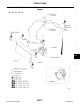
REFRIGERANT LINES Components EJS002T6 A QR25DE Models B C D E F G H I MTC K L M WJIA0981E Revision: March 2005 MTC-91 2005 Altima
REFRIGERANT LINES VQ35DE Models WJIA0982E NOTE: Refer to MTC-6, "Precautions for Refrigerant Connection" .
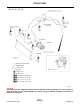
REFRIGERANT LINES Removal and Installation for Compressor — QR25DE Models EJS002T7 A B C D E F WJIA0182E REMOVAL G 1. 2. 3. 4. H 5. Discharge the refrigerant. Refer toMTC-89, "HFC-134a (R-134a) Service Procedure" . Remove the drive belt. Refer to EM-15, "Removal and Installation" . Disconnect the compressor connector. Remove the high-pressure flexible hose and low-pressure flexible hose.
REFRIGERANT LINES Removal and Installation for Compressor — VQ35DE Models EJS002T8 WJIA0117E REMOVAL 1. 2. 3. 4. 5. 6. 7. Discharge the refrigerant. Refer to MTC-89, "HFC-134a (R-134a) Service Procedure" . Remove the drive belt. Refer to MA-22, "Checking Drive Belts" . Remove the coolant pipe bracket bolt using power tools. Remove the compressor mounting stud. Disconnect the compressor connector. Remove the high-pressure flexible hose and low-pressure flexible hose.
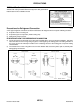
REFRIGERANT LINES 2. Remove the center bolt by holding the clutch disc steady using Tool. Tool number 3. A : (J-44614) Remove the clutch disc. B C WHA228 D 4. Remove the snap ring using external snap ring pliers. E F G RHA072C 5. Remove the pulley assembly using Tool. ● Use a pulley puller with a small adapter. Position the small adapter on the end of the compressor shaft and the center of the puller on the small adapter as shown.
REFRIGERANT LINES 8. Remove the three magnet coil screws and remove the magnet coil. WHA183 INSPECTION AFTER REMOVAL Clutch Disc If the contact surface shows signs of damage due to excessive heat, replace clutch disc and pulley. Pulley Check the appearance of the pulley assembly. If the contact surface of the pulley shows signs of excessive grooving, replace the clutch disc and pulley. The contact surfaces of the pulley assembly should be cleaned with a suitable solvent before installation.
REFRIGERANT LINES 5. Install the center bolt using Tool. Center bolt Tool number ● A : 12 N·m (1.2 kg-m, 9 ft-lb). : (J-44614) After tightening the center bolt to specification, check that the pulley rotates smoothly. B C WHA229 INSPECTION AFTER INSTALLATION D Check the clearance all the way around the clutch disc as shown. Clutch disc-to-pulley clearance E : 0.3 - 0.6 mm (0.012 - 0.024 in) If the specified clearance is not obtained, replace the adjusting spacer and recheck the clearance.
REFRIGERANT LINES Removal and Installation for Low-pressure Flexible Hose EJS002TA REMOVAL 1. 2. 3. Discharge the refrigerant. Refer to MTC-89, "HFC-134a (R-134a) Service Procedure" . Remove the refrigerant pressure sensor. Remove the low-pressure flexible hose. Refer to MTC-91, "Components" . CAUTION: Cap or wrap the joint of the hose with a suitable material such as vinyl tape to avoid the entry of contaminants. INSTALLATION Installation is in the reverse order of removal.
REFRIGERANT LINES High-pressure pipe (evaporator side) bolt : 2.9 - 5.9 N·m (0.29 - 0.60 kg-m, 26 - 52 in-lb) High-pressure pipe (condenser side) bolt : 7.8 - 19.6 N·m (0.8 - 1.9 kg-m, 69 - 173 in-lb) A CAUTION: ● Replace the O-ring of the high-pressure pipe with a new one, then apply compressor oil to it when installing it. ● After charging the refrigerant, check for leaks. Refer to MTC-102, "Checking for Refrigerant Leaks" .
REFRIGERANT LINES 6. 7. Remove the mounting nuts from condenser mounting brackets. Remove the condenser. WJIA0125E INSTALLATION Installation is in the reverse order of removal. High-pressure flexible hose and pipe bolt Condenser nuts : 7.8 - 19.6 N·m (0.8 - 1.9 kg-m, 69 - 173 in-lb) : 5.0 - 6.79 N·m (0.51 - 0.
REFRIGERANT LINES 10. Remove the heater core cover. A B C WJIA0127E D 11. Remove the evaporator cover. E F G WJIA0188E 12. Remove the evaporator. ● Remove the thermo control amplifier. ● Remove the intake sensor. CAUTION: ● Mark the mounting position of the intake sensor and thermo control amplifier. H I MTC WJIA0190E K INSTALLATION Installation is in the reverse order of removal. Expansion valve mounting bolts L : 2.9 - 5.0 N·m (0.29 - 0.
REFRIGERANT LINES 4. Remove the expansion valve. WJIA0128E INSTALLATION Installation is in the reverse order of removal. Expansion valve mounting bolts : 2.9 - 5.0 N·m (0.29 - 0.51 kg-m, 26 - 44 in-lb) CAUTION: ● Replace the O-rings with new ones, then apply compressor oil to them when installing them. Checking for Refrigerant Leaks EJS002TH Perform a visual inspection of all refrigeration parts, fittings, hoses and components for signs of A/C lubricant leakage, damage and corrosion.
REFRIGERANT LINES 2. 3. 4. 5. 6. 7. Pour one bottle (1/4 ounce / 7.4 cc) of the A/C refrigerant dye into the injector tool (J-41459). CAUTION: If repairing the A/C system or replacing a component, pour the dye directly into the open system connection and proceed with the service procedures. Connect the injector tool to the A/C LOW PRESSURE side service valve. Start the engine and switch the A/C ON and fan ON. While the A/C is operating (compressor running), inject one bottle (1/4 ounce / 7.
REFRIGERANT LINES 3. Move the leak detector probe along the component at approximately 25 to 50 mm (1 to 2 in)/sec. SHA708EA CHECKING PROCEDURE NOTE: To prevent inaccurate or false readings, make sure there is no refrigerant vapor, shop chemicals, or cigarette smoke in the vicinity of the vehicle. Perform the leak test in a calm area (low air/wind movement) so that the leaking refrigerant is not dispersed. 1. Turn engine OFF. 2. Connect a suitable A/C manifold gauge set to the A/C service ports. 3. 4.
REFRIGERANT LINES d. e. 9. 10. Temperature: MAX cold Fan speed: High Run engine at 1,500 rpm for at least 2 minutes. Turn engine off and perform leak check again following steps 4 through 6 above. Refrigerant leaks should be checked immediately after stopping the engine. Begin with the leak detector at the compressor. The pressure on the high pressure side will gradually drop after refrigerant circulation stops and pressure on the low pressure side will gradually rise, as shown in the graph.
SERVICE DATA AND SPECIFICATIONS (SDS) SERVICE DATA AND SPECIFICATIONS (SDS) Service Data and Specifications (SDS) PFP:00030 EJS002TL COMPRESSOR Model CALSONIC KANSEI Type DKS-17D Displacement 175.5 cm3 (10.7 in3 ) / revolution Cylinder bore × stroke 30.5 mm (1.201 in) x 21.4 mm (0.