
Owner's Manual

MTC-2
Revision: March 2005 2005 Altima
Operational Check .................................................. 40
CONDITIONS: .....................................................40
PROCEDURE: ..................................................... 40
Power Supply and Ground Circuit for Front Air Con-
trol ........................................................................... 42
COMPONENT DESCRIPTION ............................ 42
DIAGNOSTIC PROCEDURE .............................. 42
LAN System Circuit ................................................ 44
DIAGNOSTIC PROCEDURE .............................. 44
Mode Door Motor Circuit ........................................47
INSPECTION FLOW ........................................... 47
SYSTEM DESCRIPTION .................................... 48
COMPONENT DESCRIPTION ............................ 48
DIAGNOSTIC PROCEDURE .............................. 48
Air Mix Door Motor Circuit ...................................... 49
INSPECTION FLOW ........................................... 49
SYSTEM DESCRIPTION .................................... 50
COMPONENT DESCRIPTION ............................ 50
DIAGNOSTIC PROCEDURE .............................. 50
Intake Door Motor Circuit ........................................ 51
INSPECTION FLOW ........................................... 51
SYSTEM DESCRIPTION .................................... 52
COMPONENT DESCRIPTION ............................ 52
DIAGNOSTIC PROCEDURE .............................. 52
Blower Motor Circuit ............................................... 53
INSPECTION FLOW ........................................... 53
SYSTEM DESCRIPTION .................................... 54
COMPONENT DESCRIPTION ............................ 54
DIAGNOSTIC PROCEDURE .............................. 54
COMPONENT INSPECTION .............................. 58
Magnet Clutch Circuit ............................................. 59
INSPECTION FLOW ........................................... 59
SYSTEM DESCRIPTION .................................... 60
DIAGNOSTIC PROCEDURE .............................. 60
COMPONENT INSPECTION .............................. 62
Insufficient Cooling ................................................. 64
INSPECTION FLOW ........................................... 64
PERFORMANCE TEST ANALYSIS .................... 65
PERFORMANCE CHART ................................... 67
TROUBLE DIAGNOSIS FOR ABNORMAL
PRESSURE ......................................................... 67
Insufficient Heating .................................................71
INSPECTION FLOW ........................................... 71
Noise ...................................................................... 72
INSPECTION FLOW ........................................... 72
Intake Sensor Circuit .............................................. 73
COMPONENT DESCRIPTION ............................ 73
DIAGNOSTIC PROCEDURE .............................. 73
CONTROL UNIT ........................................................ 76
Removal and Installation ........................................ 76
FRONT AIR CONTROL ....................................... 76
INTAKE SENSOR .....................................................77
Removal and Installation ........................................ 77
REMOVAL ........................................................... 77
INSTALLATION .................................................... 77
BLOWER UNIT ......................................................... 78
Removal and Installation ........................................ 78
REMOVAL ........................................................... 78
INSTALLATION .................................................... 78
BLOWER MOTOR .....................................................79
Removal and Installation .........................................79
REMOVAL ............................................................79
INSTALLATION ....................................................79
IN-CABIN MICROFILTER ..........................................80
Removal and Installation .........................................80
FUNCTION ..........................................................80
REPLACEMENT TIMING ....................................80
REPLACEMENT PROCEDURES ........................80
HEATER & COOLING UNIT ASSEMBLY .................81
Removal and Installation .........................................81
REMOVAL ............................................................81
INSTALLATION ....................................................81
HEATER CORE .........................................................82
Removal and Installation .........................................82
REMOVAL ............................................................82
INSTALLATION ....................................................82
INTAKE DOOR MOTOR ............................................83
Removal and Installation .........................................83
REMOVAL ............................................................83
INSTALLATION ....................................................83
MODE DOOR MOTOR ..............................................84
Removal and Installation .........................................84
REMOVAL ............................................................84
INSTALLATION ....................................................84
AIR MIX DOOR MOTOR ...........................................85
Removal and Installation .........................................85
REMOVAL ............................................................85
INSTALLATION ....................................................85
FAN CONTROL AMPLIFIER .....................................86
Removal and Installation .........................................86
REMOVAL ............................................................86
INSTALLATION ....................................................86
DUCTS AND GRILLES .............................................87
Removal and Installation .........................................87
REMOVAL ............................................................87
INSTALLATION ....................................................88
REFRIGERANT LINES .............................................89
HFC-134a (R-134a) Service Procedure ..................89
SETTING OF SERVICE TOOLS AND EQUIP-
MENT ...................................................................89
Components ............................................................91
Removal and Installation for Compressor —
QR25DE Models .....................................................93
REMOVAL ............................................................93
INSTALLATION ....................................................93
Removal and Installation for Compressor —
VQ35DE Models .....................................................94
REMOVAL ............................................................94
INSTALLATION ....................................................94
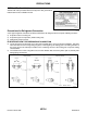
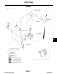
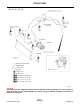
Removal and Installation for Compressor Clutch ....94
REMOVAL ............................................................94
INSPECTION AFTER REMOVAL ........................96
INSTALLATION ....................................................96
INSPECTION AFTER INSTALLATION ................97
BREAK-IN OPERATION ......................................97
Removal and Installation for Low-pressure Flexible
Hose ........................................................................98
REMOVAL ............................................................98