C TRANSMISSION/TRANSAXLE SECTION MT MANUAL TRANSAXLE A B MT D E CONTENTS RS5F51A PRECAUTIONS .......................................................... 4 Caution ..................................................................... 4 PREPARATION ........................................................... 5 Special Service Tools ............................................... 5 Commercial Service Tools ........................................ 7 NOISE, VIBRATION, AND HARSHNESS (NVH) TROUBLESHOOTING .
Baulk Ring Clearance ............................................. 64 Available Snap Rings .............................................. 65 INPUT SHAFT SPACER ..................................... 65 5TH MAIN GEAR ................................................. 65 Available C-Rings ................................................... 65 MAINSHAFT C-RING .......................................... 65 Available Thrust Washer ......................................... 65 INPUT SHAFT THRUST WASHER .............
REVERSE IDLER GEAR ADJUSTING SHIM ... 132 6TH MAIN GEAR ADJUSTING SHIM ............... 132 Available Shims .................................................... 132 BEARING PRELOAD ........................................ 132 DIFFERENTIAL SIDE BEARING ADJUSTING SHIM(S) .............................................................
PRECAUTIONS [RS5F51A] PRECAUTIONS Caution ● ● ● ● ● ● PFP:00001 ECS0093X Do not reuse transaxle oil, properly dispose of it after it has been drained out. Check the oil level or replace the oil only with the vehicle parked on level ground. During removal or installation, keep inside of transaxle clear of dust or dirt. Check for the correct installation status prior to removal or disassembly. If mating marks are required, be certain they do not interfere with the function of the parts when applied.
PREPARATION [RS5F51A] PREPARATION Special Service Tools PFP:00002 A ECS0093Y The actual shapes of Kent-Moore tools may differ from those of special tools illustrated here. B Tool number (Kent-Moore No.
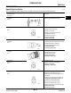
PREPARATION [RS5F51A] Tool number (Kent-Moore No.) Tool name Description KV40105020 ( — ) Drift ZZA1133D KV40105710 ( — ) Press stand ZZA1058D ST38220000 ( — ) Press stand ● Removing 5th input gear and synchronizer hub ● Removing 3rd main gear, 2nd main gear, 2nd bushing, 1st-2nd synchronizer hub, 1st main gear, reverse main gear and 1st bushing a: 39.7 mm (1.563 in) dia. b: 35 mm (1.38 in) dia. c: 15 mm (0.59 in).
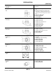
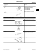
PREPARATION [RS5F51A] Tool number (Kent-Moore No.) Tool name A Description KV38102510 ( — ) Drift ● Installing 1st bushing ● Installing 1st-2nd synchronizer hub ● Installing differential side bearing B a: 71 mm (2.80 in) dia. b: 65 mm (2.56 in) dia.
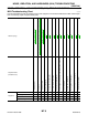
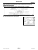
NOISE, VIBRATION, AND HARSHNESS (NVH) TROUBLESHOOTING [RS5F51A] NOISE, VIBRATION, AND HARSHNESS (NVH) TROUBLESHOOTING NVH Troubleshooting Chart PFP:00003 ECS00940 Jumps out of gear Revision: March 2005 3 3 3 3 2 2 1 MT-8 MT-62 1 Insert Spring (Damaged) 1 2 MT-40 Hard to shift or will not shift 2 Baulk Ring (Worn or damaged) MT-40 Check Plug Return Spring and Check Ball (Worn or damaged) 1 MT-40 MT-14 Shift Control Linkage (Worn) 3 Bearing (Worn or damaged) MT-11 O-Ring (Worn or dam
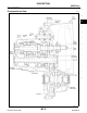
DESCRIPTION [RS5F51A] DESCRIPTION Cross-sectional View PFP:00000 A ECS00941 B MT D E F G H I J K L M WCIA0342E Revision: March 2005 MT-9 2005 Altima
DESCRIPTION [RS5F51A] DOUBLE-CONE SYNCHRONIZER Double-cone synchronizer is adopted for 1st and 3rd gears to reduce operating force of the shift lever. TRIPLE-CONE SYNCHRONIZER Triple cone synchronizer is adopted for 2nd gear to reduce operating force of the shift lever. PCIB0774E REVERSE GEAR See figure for description of reverse gear components.
M/T OIL [RS5F51A] M/T OIL Replacement PFP:KLD20 A ECS00942 DRAINING 1. 2. 3. Start the engine and let it run to warm up the transaxle oil. Stop the engine. Remove drain plug and drain oil. Set a gasket on the drain plug and install it in transaxle case. Drain plug B : 30 - 39 N·m (3.1 - 4.0 kg-m, 23 - 28 ft-lb) MT CAUTION: Do not reuse gasket. D FILLING 1. Remove speedometer pinion gear. Fill the transaxle with new oil. Oil grade and capacity 2. E : Refer to MA-12, "Fluids and Lubricants" .
SIDE OIL SEAL [RS5F51A] SIDE OIL SEAL Removal and Installation PFP:32113 ECS00944 REMOVAL 1. 2. Remove the drive shaft from the transaxle case. Refer to FAX-11, "Removal and Installation" . Remove the oil seal using suitable tool. CAUTION: Be careful not to damage the transaxle case surface when removing the oil seal. WCIA0023E INSTALLATION Installation is in the reverse order of removal.
POSITION SWITCH [RS5F51A] POSITION SWITCH Removal and Installation PFP:32005 A ECS00945 Refer to MT-20, "CASE AND HOUSING COMPONENTS" . B Checking ECS00946 BACK-UP LAMP SWITCH ● Check continuity. MT Gear position Continuity Reverse Yes Except reverse No D E SCIA0708E F PARK/NEUTRAL POSITION SWITCH ● Check continuity.
CONTROL LINKAGE [RS5F51A] CONTROL LINKAGE Removal and Installation PFP:34103 ECS00947 WCIA0203E 1. Snap pin 2. Washer 3. Cable 4. Manual lever 5. Shift cable 6. Lock plate 7. Control device assembly 8. Lock plate 9. Select cable 10. Shift cable Revision: March 2005 11. Control lever knob MT-14 12.
CONTROL LINKAGE [RS5F51A] 13. Control device assembly 14. Cover plate 15. Select cable 16. Floor pan 17. Control lever 18. Shift cable 19. Washer 20. Clutch housing 21. Cable mounting bracket 22. Select cable 23. Shift cable 24. Lock plate A B 25. Lock plate CAUTION: ● Note that the select side lock plate for securing the control cable is different from the one on the MT shift side.
AIR BREATHER HOSE [RS5F51A] AIR BREATHER HOSE Removal and Installation PFP:31098 ECS00949 Refer to the figure for air breather hose removal and installation information. QR25DE Engine LCIA0033E VQ35DE Engine LCIA0034E CAUTION: ● Make sure there are no pinched or restricted areas on the air breather hose caused by bending or twisting when installing it. ● Be sure to insert hose into the transaxle tube until overlap area reaches the spool.
TRANSAXLE ASSEMBLY [RS5F51A] TRANSAXLE ASSEMBLY Removal and Installation PFP:32010 A ECS0094A B MT D E F G H I WCIA0194E J REMOVAL 1. 2. 3. 4. 5. 6. 7. 8. 9. 10. 11. 12. 13. Remove the air cleaner and air duct. Refer to EM-17, "Removal and Installation" (QR25DE), EM-120, "Removal and Installation" (VQ35DE). Remove the battery tray and battery. Remove air breather hose from the transaxle. Remove the clutch operating cylinder and position it aside without disconnecting the hydraulic lines.
TRANSAXLE ASSEMBLY [RS5F51A] 14. Lower vehicle, then install a suitable engine slinger on the front of the left bank cylinder head, and on the rear of the right bank cylinder head as shown. SEM807G SEM808G 15. Support the engine using an engine support fixture or suitable tool. 16. Remove the five upper bolts that mount the transaxle to the engine using power tool. 17. Disconnect the LH transaxle mounting insulator using power tool. 18.
TRANSAXLE ASSEMBLY [RS5F51A] INSTALLATION A Installation is in the reverse order of removal. ● When installing the transaxle to the engine, use the specified tightening torque in the numerical sequence shown below: B CAUTION: When installing the transaxle, do not allow the transaxle input shaft to make contact with the clutch cover. MT QR engine models: Bolt No. 1 2 3 4 5 6 7 8 9 10 Bolt length “ ” mm (in) 40 (1.57) 82 (3.2 3) 47 (1.8 5) 47 (1.8 5) 52 (2.0 5) 40 (1.5 7) 40 (1.5 7) 40 (1.
TRANSAXLE ASSEMBLY [RS5F51A] Component Parts ECS0094B CASE AND HOUSING COMPONENTS WCIA0430E 1. Differential oil seal 2. Ball pin 3. Washer 4. Back-up lamp switch 5. Oil gutter 6. Baffle plate 7. Transaxle case 8. Filler plug 9. Gasket 10. Welch plug 11. Bore plug 12. Drain plug 13. Gasket 14. Differential oil seal 15. Park/Neutral position switch 16. Air breather tube 17. Input shaft oil seal 18. Oil channel 19. Magnet 20. Clutch housing 21. Speedometer pinion gear 22.
TRANSAXLE ASSEMBLY [RS5F51A] GEAR COMPONENTS A B MT D E F G H WCIA0431E 1. Input shaft front bearing 2. Input shaft 3. Needle bearing 4. 3rd input gear 5. 3rd inner baulk ring 6. 3rd gear synchronizer cone 7. 3rd outer baulk ring 8. Spread spring 9. 3rd and 4th synchronizer hub 10. 3rd and 4th shifting insert 11. 4th baulk ring 12. 3rd and 4th coupling sleeve 13. Bushing 14. Needle bearing 15. 4th input gear 16. Thrust washer 17. Bushing 18. Needle bearing 19.
TRANSAXLE ASSEMBLY [RS5F51A] SCIA0386E 1. Mainshaft front bearing 2. Mainshaft bearing retainer 3. Mainshaft 4. Reverse main gear 5. 1st main gear 6. Bushing 7. Needle bearing 8. 1st inner baulk ring 9. 1st gear synchronizer cone 10. 1st outer baulk ring 11. Spread spring 12. 1st & 2nd shifting insert 13. 1st & 2nd synchronizer hub 14. 2nd outer baulk ring 15. 2nd gear synchronizer cone 16. 2nd inner baulk ring 17. 1st & 2nd coupling sleeve 18. Bushing 19.
TRANSAXLE ASSEMBLY [RS5F51A] SHIFT CONTROL COMPONENTS A B MT D E F G H I J K L M WCIA0260E 1. Stopper ring 2. 5th & reverse bracket 3. 4. Shifter cap 5. Reverse shift fork 6. Reverse lever assembly Reverse fork rod 7. Check plug 8. Check spring 9. Shift check sleeve 10. Check ball 11. 3rd & 4th fork rod 12. 5th and reverse fork rod 13. 5th shift fork 14. Retaining pin 15. Stopper bolt 16. Shift check 17. Control rod assembly 18. O-ring 19.
TRANSAXLE ASSEMBLY [RS5F51A] FINAL DRIVE COMPONENTS WCIA0208E 1. Differential side bearing outer race 2. Differential side bearing 3. Speedometer drive gear 4. Differential case 5. Final gear 6. Differential side bearing 7. Differential side bearing outer race 8. Differential side bearing adjusting shim 9. Pinion mate shaft 10. Side gear 11. Side gear thrust washer 13. Pinion mate gear washer 14. Retaining pin Disassembly and Assembly 12. Pinion mate gear ECS0094C DISASSEMBLY 1.
TRANSAXLE ASSEMBLY [RS5F51A] 4. Remove check plugs (3 pieces), check springs (3 pieces), check balls (3 pieces) and shift check sleeve (1 piece). A B MT SCIA0396E D 5. Remove transaxle case bolts. E F G SCIA0983E 6. Remove the bore plug. CAUTION: Be careful not to damage transaxle case. 7. While spreading the snap ring of mainshaft rear bearing located at bore plug hole, remove transaxle case. 8. Remove the oil gutter and baffle plate. 9.
TRANSAXLE ASSEMBLY [RS5F51A] 12. Remove differential oil seal. SCIA0397E 13. Remove magnet from clutch housing. 14. With shift lever in 5th position, remove bracket bolts from reverse lever assembly. Lift reverse lever assembly to remove. CAUTION: Be careful not to lose shifter cap. SCIA0390E 15. Pull out reverse fork rod then remove reverse shift fork. 16. Shift 3rd & 4th fork rod to 3rd position. Remove retaining pin of 5th shift fork using pin punch. SCIA0391E 17.
TRANSAXLE ASSEMBLY [RS5F51A] 20. Remove retaining pin of 3rd & 4th bracket using pin punch. A B MT SCIA0393E D 21. 22. 23. 24. Remove stopper rings for 3rd & 4th shift fork. Pull out 3rd & 4th fork rod and remove 3rd & 4th shift fork and bracket. Remove shift check sleeve from clutch housing. Remove retaining pin of 1st & 2nd shift fork using pin punch. E F G H SCIA0394E 25. 26. 27. 28. a. Pull out 1st & 2nd with bracket. Remove 1st & 2nd shift fork.
TRANSAXLE ASSEMBLY [RS5F51A] 32. Remove differential side bearing outer race (clutch housing side). Tool number : KV381054S0 (J-34286) WCIA0272E 33. Remove input shaft oil seal. CAUTION: Be careful not to damage clutch housing. SCIA0398E ASSEMBLY 1. Using a drift, install a new input shaft oil seal from the clutch housing end of side to the depth of 1.8 - 2.8 mm (0.071 - 0.110 in). CAUTION: Oil seals are not reusable. SCIA1022E 2. Using a drift, install a new differential oil seal.
TRANSAXLE ASSEMBLY [RS5F51A] 4. Using a drift, install mainshaft front bearing. CAUTION: Use the correct orientation for installation as shown. Tool number A : ST33200000 (J-26082) B MT WCIA0274E 5. Install bearing retainer. CAUTION: Install with the punched surface facing up. D E F G SCIA0400E 6. Install differential side bearing outer race. Tool number H : ST30720000 (J-25405) I J WCIA0275E 7. K Install final drive assembly into clutch housing. L M SCIA0888E 8.
TRANSAXLE ASSEMBLY [RS5F51A] 9. Install 1st-2nd fork rod bracket onto 1st-2nd fork rod, and then install retaining pin. CAUTION: Retaining pins are not reusable. Never reuse them. SCIA0889E 10. Install 1st-2nd fork rod and 1st-2nd shift fork, and then install retaining pin. CAUTION: Retaining pins are not reusable. Never reuse them. SCIA0394E 11. Install shift check sleeve. 12. Install 3rd-4th bracket, 3rd-4th shift fork, and 3rd-4th fork rod with interlock pin. SCIA0393E 13.
TRANSAXLE ASSEMBLY [RS5F51A] CAUTION: Stopper rings are not reusable. Never reuse them. 18. Install retaining pin onto 5th shift fork. CAUTION: Retaining pins are not reusable. Never reuse them. A B MT D SCIA0391E 19. Install reverse shift fork and reverse fork rod. 20. Install reverse lever assembly following procedures below. a. Install shifter cap onto reverse lever assembly cam, and then install them onto reverse shift fork. CAUTION: Do not drop shifter cap. b.
TRANSAXLE ASSEMBLY [RS5F51A] c. Apply Genuine Silicone RTV or equivalent to mating surfaces of transaxle case and clutch housing. Refer to GI-45, "RECOMMENDED CHEMICAL PRODUCTS AND SEALANTS" . CAUTION: Remove old sealant adhering to mounting surfaces. Also remove any moisture, oil, or foreign material adhering to application and mounting surfaces. SCIA0891E d. With snap ring of mainshaft rear bearing temporarily installed, place transaxle case over clutch housing. SCIA0892E e.
TRANSAXLE ASSEMBLY [RS5F51A] g. Tighten the bolts “A” and the new bolts “B”. Bolt “A” Bolt “B” A : 50.0 - 53.9 N·m (5.1 - 5.4 kg-m, 37 - 39 ft-lb) : 63.0 - 66.9 N·m (6.5 - 6.8 kg-m, 47 - 49 ft-lb) CAUTION: Always replace bolts “B” because they are self-sealing bolts. B MT SCIA1064E D h. Apply gear oil to the O-ring and install it to the control assembly. Then install control assembly to transaxle case. Tighten bolts to the specified torque. Refer to MT-23, "SHIFT CONTROL COMPONENTS" .
TRANSAXLE ASSEMBLY [RS5F51A] 29. Apply Genuine Silicone RTV or equivalent to threads of Park/ Neutral position switch and Back-up lamp switch, then install them into transaxle case. Refer to GI-45, "RECOMMENDED CHEMICAL PRODUCTS AND SEALANTS" . SCIA0895E 30. Install gaskets onto drain plug and filler plug, then install them into transaxle case. CAUTION: ● Gaskets are not reusable. Never reuse them. ● After oil is filled, tighten filler plug to specified torque.
TRANSAXLE ASSEMBLY [RS5F51A] 1. Using depth micrometer and straight edge, measure dimension “O1 ” between transaxle case end face and mounting face of adjusting shim as shown. A B MT SCIA1002E D 2. Using depth micrometer and straight edge, measure dimension “O2 ” between clutch housing case end face and end face of input shaft rear bearing as shown. E F G SCIA1004E 3. Install selected input shaft rear bearing adjusting shim onto input shaft.
TRANSAXLE ASSEMBLY [RS5F51A] 1. Using depth micrometer and straightedge, measure dimension “L1 ” between transaxle case end face and mounting face of adjusting shim as shown. SCIA1078E 2. 3. Install outer race onto differential side bearing on final gear side. Holding lightly the outer race horizontally by hand, rotate final gear five times or more (for smooth movement of bearing roller).
TRANSAXLE ASSEMBLY [RS5F51A] Adjusting Shim Shim thickness Part number 0.44 mm (0.0173 in) 0.48 mm (0.0189 in) 0.52 mm (0.0205 in) 0.56 mm (0.0220 in) 0.60 mm (0.0236 in) 0.64 mm (0.0252 in) 0.68 mm (0.0268 in) 0.72 mm (0.0283 in) 0.76 mm (0.0299 in) 0.80 mm (0.0315 in) 0.84 mm (0.0331 in) 0.88 mm (0.0346 in) 0.92 mm (0.0362 in) 0.96 mm (0.0378 in) 1.00 mm (0.0394 in) 1.04 mm (0.0409 in) 1.08 mm (0.
TRANSAXLE ASSEMBLY [RS5F51A] Adjusting Shim Shim thickness mm (in) 1.76 (0.0693) 1.80 (0.0709) 1.84 (0.0724) 1.88 (0.0740) 1.92 (0.0756) 1.96 (0.0772) 2.00 (0.0787) 2.04 (0.0803) 2.08 (0.0819) 2.12 (0.0835) 2.16 (0.0850) 2.20 (0.0866) Part number Shim thickness 32237 8H800 32237 8H801 32237 8H802 32237 8H803 32237 8H804 32237 8H805 32237 8H806 32237 8H807 32237 8H808 32237 8H809 32237 8H810 32237 8H811 mm (in) 2.24 (0.0882) 2.28 (0.0898) 2.32 (0.0913) 2.36 (0.0929) 2.40 (0.0945) 2.44 (0.0961) 2.
INPUT SHAFT AND GEARS [RS5F51A] INPUT SHAFT AND GEARS Disassembly and Assembly PFP:32200 A ECS0094E DISASSEMBLY 1. Before disassembling, measure end play for 3rd, 4th, and 5th input gears. B End play standard value 3rd gear : 0.18 - 0.31 mm (0.0071 - 0.0122 in) 4th gear : 0.20 - 0.30 mm (0.0079 - 0.0118 in) 5th gear : 0.06 - 0.16 mm (0.0024 - 0.0063 in) CAUTION: If measurement is outside the standard range, disassemble to check contact surfaces of gear, shaft, and hub.
INPUT SHAFT AND GEARS [RS5F51A] 6. Remove 5th input gear and synchronizer hub assembly simultaneously. Tool number A: KV40105020 ( — ) B: Commercial service tool WCIA0281E 7. 8. Remove 5th needle bearing. Remove 5th bushing, thrust washer, 4th input gear, 4th needle bearing, 4th gear bushing, 4th baulk ring, 3rd-4th synchronizer hub assembly, 3rd gear synchronizer assembly, and 3rd input gear simultaneously. Tool number A: ST33052000 ( — ) B: Commercial service tool WCIA0282E 9.
INPUT SHAFT AND GEARS [RS5F51A] Synchronizer A Check items below. If necessary, replace them with new ones. ● Damage and excessive wear of contact surfaces of coupling sleeve, synchronizer hub, and shifting insert. ● Coupling sleeve and synchronizer hub must move smoothly. B MT SMT387A ● If any crack, damage, or excessive wear is found on cam face of baulk ring or working face of insert, replace it.
INPUT SHAFT AND GEARS [RS5F51A] ● Measure clearance “A” at two or more points diagonally opposite using a dial indicator, and calculate average value. Tool number Clearance “A” Standard value Limit value A: ST30031000 (J-22912-01) : 0.6 – 0.8 mm (0.024 – 0.031 in) : 0.2 mm (0.008 in) WCIA0283E ● Measure clearance “B” at two or more points diagonally opposite using a feeler gauge, and calculate average value. Clearance “B” Standard value Limit value : 0.6 – 1.1 mm (0.024 – 0.043 in) : 0.2 mm (0.
INPUT SHAFT AND GEARS [RS5F51A] ● Be careful with orientation of coupling sleeve. A B MT SCIA0993E D ● Be sure not to hook ends of 2 spread springs (front and back have two each) on same shifting insert. E F G SCIA1083E 4. Install 3rd-4th synchronizer hub assembly. Tool number H : KV40105710 ( — ) CAUTION: Align grooves of shifting insert and 3rd baulk ring. I J WCIA0284E 5. K Install 4th bushing. Tool number : KV40105710 ( — ) L M WCIA0285E 6. 7. Install 4th baulk ring.
INPUT SHAFT AND GEARS [RS5F51A] 8. Select thrust washer so that dimension “C2 ” satisfies standard below. Then install it onto input shaft. Standard for dimension “C2 ” : 154.7 - 154.8 mm (6.091 - 6.094 in) SCIA0925E Thrust Washer Thickness Part number Thickness Part number 3.84 mm (0.1512 in) 3.90 mm (0.1535 in) 3.96 mm (0.1559 in) 32347 8H500 32347 8H501 32347 8H502 4.02 mm (0.1583 in) 4.08 mm (0.1606 in) 4.14 mm (0.
INPUT SHAFT AND GEARS [RS5F51A] ● Be careful with orientation of coupling sleeve. A B MT SCIA0994E D ● Be sure not to hook ends of 2 spread springs (front and back have two each) on same shifting insert. E F G SCIA1083E 13. Install 5th synchronizer hub assembly. Tool number H : KV40105710 ( — ) CAUTION: Align grooves of 5th shifting insert and 5th baulk ring. I J WCIA0287E K 14. Install 5th stopper and then input shaft bearing spacer.
INPUT SHAFT AND GEARS [RS5F51A] Snap Rings Thickness Part number Thickness Part number 1.71 mm (0.0673 in) 1.76 mm (0.0693 in) 1.81 mm (0.0713 in) 1.86 mm (0.0732 in) 1.91 mm (0.0752 in) 1.96 mm (0.0772 in) 32204 8H510 32204 8H511 32204 8H512 32204 8H513 32204 8H514 32204 8H515 2.01 mm (0.0791 in) 2.06 mm (0.0811 in) 2.11 mm (0.0831 in) 2.16 mm (0.0850 in) 2.21 mm (0.0871 in) 2.26 mm (0.0890 in) 32204 8H516 32204 8H517 32204 8H518 32204 8H519 32204 8H520 32204 8H521 16.
MAINSHAFT AND GEARS [RS5F51A] MAINSHAFT AND GEARS Disassembly and Assembly PFP:32241 A ECS0094F DISASSEMBLY 1. Before disassembling, measure end play of 1st and 2nd main gears. B End play standard value 1st gear : 0.20 - 0.30 mm (0.0079 - 0.0118 in) 2nd gear : 0.06 - 0.16 mm (0.0024 - 0.0063 in) MT CAUTION: If measurement is outside the standard range, disassemble to check contact surfaces of gear, shaft, and hub. Adjust with snap ring at assembly. D SCIA0933E 2. 3. Remove the snap ring.
MAINSHAFT AND GEARS [RS5F51A] 6. Remove 4th main gear and 5th main gear simultaneously. Tool number 7. 8. A: ST33052000 ( — ) B: Commercial service tool Remove adjusting shim. Remove 3rd-4th mainshaft spacer. WCIA0292E 9. Remove 3rd main gear, 2nd main gear, 2nd needle bearing, 2nd bushing, 1st-2nd synchronizer hub assembly, 1st main gear, reverse main gear, 1st needle bearing, and 1st bushing simultaneously.
MAINSHAFT AND GEARS [RS5F51A] ● If any crack, damage, or excessive wear is found on cam face of baulk ring or working face of insert, replace it. A B MT SMT867D D Baulk Ring Clearance for Double Cone Synchronizer (1st) Follow the instructions below and inspect the clearance of outer baulk ring, synchronizer cone, and inner baulk ring. CAUTION: Outer baulk ring, synchronizer cone and inner baulk ring determine the clearances “A” and “B” as an assembly.
MAINSHAFT AND GEARS [RS5F51A] Baulk Ring Clearance for Triple Cone Synchronizer (2nd) Follow the instructions below and inspect the clearance of outer baulk ring, synchronizer cone, inner baulk ring. CAUTION: Outer baulk ring, synchronizer cone and inner baulk ring determine the clearances “A”, “B” and ”C” as an assembly. Replace the outer baulk ring, synchronizer cone and inner baulk ring as an assembly if any of the clearances “A”, “B” and “C” exceed the limit value.
MAINSHAFT AND GEARS [RS5F51A] Bearing A Check items below. If necessary, replace them with new ones. ● Damage and rough rotation of bearing B MT MTF0041D D ASSEMBLY 1. Install reverse main gear. Tool number E A: ST35321000 ( — ) B: KV40101630 (J-35870) C: ST38220000 ( — ) F G WCIA0294E CAUTION: Be careful with orientation of reverse main gear. H I J K SCIA0992E 2. Install 1st bushing. Tool number 3.
MAINSHAFT AND GEARS [RS5F51A] CAUTION: ● Be careful with orientation of synchronizer hub. SCIA0921E ● Be careful with orientation of coupling sleeve. SCIA0989E ● Be sure not to hook ends of 2 spread springs (front and back have two each) on same shifting insert. SCIA1083E 5. Install 1st gear synchronizer assembly onto mainshaft, and synchronizer hub assembly onto mainshaft.
MAINSHAFT AND GEARS [RS5F51A] 6. Install 2nd bushing. Tool number 7. 8. A A: ST35321000 ( — ) B: KV40105710 ( — ) Install outer baulk ring, synchronizer cone, and inner baulk ring on 2nd gear-side. Install 2nd needle bearing and 2nd gear. B MT WCIA0297E D 9. Install 3rd main gear. Tool number A: ST35321000 ( — ) B: KV40105710 ( — ) E CAUTION: Be careful with orientation of 3rd main gear. 10. Install 3rd-4th mainshaft spacer. F G WCIA0298E 11.
MAINSHAFT AND GEARS [RS5F51A] 12. Install 4th main gear. Tool number A: ST33200000 (J-26082) B: ST30901000 (J-26010-01) CAUTION: Be careful with orientation of 4th main gear. WCIA0299E 13. Install 5th main gear. Tool number A: ST33200000 (J-26082) B: ST30901000 (J-26010-01) CAUTION: Be careful with orientation of 5th main gear. WCIA0300E 14. Install snap ring onto mainshaft, and check that end play of 5th main gear satisfies standard value. End play standard value ● : 0 - 0.1 mm (0 - 0.
MAINSHAFT AND GEARS [RS5F51A] 16. Install C-ring onto mainshaft, and check that end play of mainshaft rear bearing satisfies standard value. End play standard value ● A : 0 - 0.06 mm (0 - 0.0024 in) If measurement is outside the standard range, reselect C-ring. B MT SCIA0949E D C-ring Thickness Part number Thickness Part number 2.535 mm (0.0998 in) 2.565 mm (0.1010 in) 2.595 mm (0.1022 in) 2.625 mm (0.1033 in) 2.655 mm (0.1045 in) 2.685 mm (0.1057 in) 2.715 mm (0.1069 in) 2.745 mm (0.1081 in) 2.
REVERSE IDLER SHAFT AND GEARS [RS5F51A] REVERSE IDLER SHAFT AND GEARS Disassembly and Assembly PFP:32281 ECS0094G DISASSEMBLY 1. 2. 3. 4. 5. 6. 7. 8. 9. Remove reverse idler gear adjusting shim. Remove reverse idler gear (rear), reverse coupling sleeve and insert spring simultaneously. Remove reverse idler gear needle bearing. Remove thrust needle bearing. Remove reverse baulk ring. Remove reverse idler gear (front). Remove reverse idler gear needle bearing. Remove thrust needle bearing.
REVERSE IDLER SHAFT AND GEARS [RS5F51A] Baulk Ring Clearance ● A Press baulk ring against cone, and measure clearance between baulk ring and cone. If measurement is below limit, replace it with a new one. Clearance Standard Limit value B : 0.95 - 1.4 mm (0.0374 - 0.055 in) : 0.7 mm (0.028 in) MT SMT140 D Bearing Check items below. If necessary, replace them with new ones. ● Damage and rough rotation of bearing.
FINAL DRIVE [RS5F51A] FINAL DRIVE Disassembly and Assembly PFP:38411 ECS0094H PRE-INSPECTION Check the clearance between side gear and differential case using Tool and a dial indicator as follows: Tool number : — (J-39713) WCIA0261E 1. 2. 3. Clean final drive assembly sufficiently to prevent side gear thrust washer, differential case, side gear, and other parts from sticking by gear oil. Upright the differential case so that the side gear to be measured faces upward.
FINAL DRIVE [RS5F51A] 4. Remove the differential side bearing (transaxle case side) using the pullers and Tool as shown. Tool number A A: Commercial service tool B: Commercial service tool C: ST33061000 (J-8107-2) B MT WCIA0303E 5. D Pull out the lock pin and pinion mate shaft using a pin punch. E F G SCIA0908E 6. Rotate pinion mate gears, and remove pinion mate gears, pinion mate thrust washers, side gears, and side gear thrust washers from the differential case.
FINAL DRIVE [RS5F51A] 2. Install side gear thrust washers and side gears into differential case. SMT839 3. 4. While rotating pinion mate thrust washers and pinion mate gears, aligning them diagonally, install them into differential case. Insert pinion mate shaft into differential case. CAUTION: Be sure not to damage pinion mate thrust washers. MTK0132D 5. Measure end play of side gears using the procedure below, then select a side gear thrust washer. Tool number a. b.
FINAL DRIVE [RS5F51A] 6. Drive a new lock pin into the pinion mate shaft using suitable tool. CAUTION: Do not reuse the lock pin. A B MT SCIA0908E D 7. Install differential side bearing (transaxle case side) using Tools as shown. Tool number A: ST30720000 (J-25405) B: KV38102510 ( — ) E F G WCIA0304E 8. Align and install speedometer drive gear onto differential case. H I J SMT842D 9. K Install differential side bearing (clutch housing side) using Tools as shown.
SHIFT CONTROL [RS5F51A] SHIFT CONTROL Inspection PFP:32982 ECS0094I Check contact surfaces and sliding area for wear, damage, bending, etc. If necessary, replace parts. ● SCIA0913E SHIFT FORK Check if the width of shift fork hook (sliding area with coupling sleeve) is within allowable specification below. ● Item One-side wear specification Sliding width of new part 1st & 2nd 0.2 mm (0.008 in) 7.80 - 7.93 mm (0.3071 - 0.3122 in) 3rd & 4th 0.2 mm (0.008 in) 7.80 - 7.93 mm (0.3071 - 0.
SERVICE DATA AND SPECIFICATIONS (SDS) [RS5F51A] SERVICE DATA AND SPECIFICATIONS (SDS) General Specifications PFP:00030 A ECS0094J TRANSAXLE Engine QR25DE VQ35DE Transaxle model B RS5F51A Model code number 9J506 9J504 Number of speed MT 5 Synchromesh type Warner D Shift pattern E SCIA0821E Gear ratio 1st 3.416 3.153 2nd 1.944 1.842 3rd 1.258 4th 0.947 5th 0.772 Reverse Number of teeth Input gear 3.
SERVICE DATA AND SPECIFICATIONS (SDS) [RS5F51A] FINAL GEAR Engine QR25DE Transaxle model VQ35DE RS5F51A Model code number 9J506 9J504 Final gear ratio 4.133 3.812 Final gear/Pinion 62/15 61/16 Side gear/Pinion mate gear 14/10 14/10 Number of teeth Triple cone synchronizer 2nd Gear End Play ECS0094K Unit: mm (in) Gear End play 1st main gear 0.20 - 0.30 (0.0079 - 0.0118) 2nd main gear 0.06 - 0.16 (0.0024 - 0.0063) 3rd input gear 0.18 - 0.31 (0.0071 - 0.0122) 4th input gear 0.
SERVICE DATA AND SPECIFICATIONS (SDS) [RS5F51A] Available Snap Rings ECS0094M A INPUT SHAFT SPACER End play 0 - 0.1 mm (0 - 0.004 in) Thickness mm (in) 1.71 (0.0673) 1.76 (0.0693) 1.81 (0.0713) 1.86 (0.0732) 1.91 (0.0752) 1.96 (0.0772) Part number* Thickness 32204 8H510 32204 8H511 32204 8H512 32204 8H513 32204 8H514 32204 8H515 mm (in) 2.01 (0.0791) 2.06 (0.0811) 2.11 (0.0831) 2.16 (0.0850) 2.21 (0.0871) 2.26 (0.
SERVICE DATA AND SPECIFICATIONS (SDS) [RS5F51A] DIFFERENTIAL SIDE GEAR THRUST WASHER Allowable clearance between side gear and differential case with washer Thickness 0.1 - 0.2 mm (0.004 - 0.008 in) mm (in) Part number* 0.75 (0.0295) 0.80 (0.0315) 0.85 (0.0335) 0.90 (0.0354) 0.95 (0.0374) 38424 81X00 38424 81X01 38424 81X02 38424 81X03 38424 81X04 *: Always check with the Parts Department for the latest parts information.
SERVICE DATA AND SPECIFICATIONS (SDS) [RS5F51A] MAINSHAFT REAR BEARING ADJUSTING SHIM End play A 0 - 0.06 mm (0 - 0.0024 in) Thickness mm (in) 0.44 (0.0173) 0.48 (0.0189) 0.52 (0.0205) 0.56 (0.0220) 0.60 (0.0236) 0.64 (0.0252) 0.68 (0.0268) 0.72 (0.0283) 0.76 (0.0299) Part number* Thickness 32238 8H510 32238 8H511 32238 8H512 32238 8H513 32238 8H514 32238 8H515 32238 8H516 32238 8H517 32238 8H518 mm (in) 0.80 (0.0315) 0.84 (0.0331) 0.88 (0.0346) 0.92 (0.0362) 0.96 (0.0378) 1.00 (0.0394) 1.04 (0.
PRECAUTIONS [RS6F51A] PRECAUTIONS Caution ● ● ● ● ● ● PFP:00001 ECS0094R Do not reuse transaxle oil. Drain, fill and check transaxle oil with the vehicle on level ground. During removal and installation, keep inside of transaxle clean of dust and dirt. Check for the correct installation orientation prior to removal or disassembly. If mating marks are required, be certain they do not interfere with the function of the parts they are applied to.
PREPARATION [RS6F51A] PREPARATION Special Service Tools PFP:00002 A ECS0094S The actual shapes of Kent-Moore tools may differ from those of special tools illustrated here. B Tool number (Kent-Moore No.
PREPARATION [RS6F51A] Tool number (Kent-Moore No.) Tool name Description KV40105020 ( — ) Drift ZZA1133D Removing 5th input gear and synchronizer hub Removing 3rd main gear, 2nd main gear, 2nd bushing, 1st-2nd synchronizer hub, 1st main gear, reverse main gear and 1st bushing a: 39.7 mm (1.563 in) dia. b: 35 mm (1.38 in) dia. c: 15 mm (0.
PREPARATION [RS6F51A] Tool number (Kent-Moore No.) Tool name A Description KV38102510 (J-35870) Drift Installing 1st bushing Installing 1st-2nd synchronizer hub Installing differential side bearing a: 71 mm (2.80 in) dia. b: 65 mm (2.56 in) dia.
NOISE, VIBRATION, AND HARSHNESS (NVH) TROUBLESHOOTING [RS6F51A] NOISE, VIBRATION, AND HARSHNESS (NVH) TROUBLESHOOTING NVH Troubleshooting Chart PFP:00003 ECS0094U 3 1 Hard to shift or will not shift 1 1 Jumps out of gear Revision: March 2005 2 MT-84 MT-88 Bearing (worn or damaged) 3 3 2 2 1 MT-72 Shift fork (worn) O-Ring (worn or damaged) Oil seal (worn or damaged) Gasket (damaged) 2 3 Insert spring, shifting insert (damaged) Oil leakage 3 Baulk ring (worn or damaged) Symptom Gea
DESCRIPTION [RS6F51A] DESCRIPTION Cross-sectional View PFP:00000 A ECS0094V B MT D E F G H I J K L M WCIA0263E Revision: March 2005 MT-73 2005 Altima
DESCRIPTION [RS6F51A] 1. Input shaft rear bearing 4. 5th input gear 5. 4th input gear 6. 3rd & 4th synchronizer 7. 3rd input gear 8. Reverse idler gear (rear) 9. Reverse synchronizer 10. Reverse idler gear (front) 2. 6th input gear 11. Reverse idler shaft 3. 5th & 6th synchronizer 12. Clutch housing 13. Input shaft front bearing 14. Input shaft 15. Mainshaft 16. Mainshaft front bearing 17. Differential side bearing (front) 18. Final gear 19. Differential case 20.
M/T OIL [RS6F51A] M/T OIL Replacement PFP:KLD20 A ECS0094W DRAINING 1. 2. 3. Start the engine and let it run to warm up the transaxle oil. Stop the engine. Remove drain plug and drain oil. Set a gasket on the drain plug and install it in the transaxle case. Drain plug B : 34.5 N·m (3.5 kg-m, 25 ft-lb) MT CAUTION: Do not reuse gasket. D FILLING 1. Remove speedometer pinion gear. Fill transaxle with new oil. 2. E : Refer to MA-12, "Fluids and Lubricants" .
SIDE OIL SEAL [RS6F51A] SIDE OIL SEAL Removal and Installation PFP:32113 ECS0094Y REMOVAL 1. 2. Remove the drive shaft from the transaxle case. Refer to FAX-11, "Removal and Installation" . Remove the oil seal with a slotted screwdriver as shown. CAUTION: Be careful not to damage the transaxle case surface when removing the oil seal. WCIA0023E INSTALLATION Installation is in the reverse order of removal.
POSITION SWITCH [RS6F51A] POSITION SWITCH Checking PFP:32005 A ECS0094Z NOTE: For removal and installation of the switches. Refer to MT-84, "CASE AND HOUSING COMPONENTS" . B BACK-UP LAMP SWITCH ● Check continuity. MT Gear position Continuity Reverse Yes Except reverse No D E SCIA0708E F PARK/NEUTRAL POSITION SWITCH ● Check continuity.
CONTROL LINKAGE [RS6F51A] CONTROL LINKAGE Removal and Installation of Control Device and Cable PFP:34103 ECS00950 WCIA0203E 1. Snap pin 2. Washer 3. Cable 4. Manual lever 5. Shift cable 6. Lock plate 7. Control device assembly 8. Lock plate 9. Select cable 10. Shift cable Revision: March 2005 11. Control lever knob MT-78 12.
CONTROL LINKAGE [RS6F51A] 13. Control device assembly 14. Cover 15. Select cable 16. Floor 17. Pin 18. Shift cable 19. Washer 20. Clutch housing 21. Cable mounting bracket 22. Select cable 23. Shift cable 24. Lock plate A B 25. Lock plate CAUTION: ● Note that the select side lock plate for securing the control cable is different from the one on the MT shift side. ● After assembly, make sure selector lever automatically returns to Neutral when it is moved to 1st, 2nd, or Reverse.
AIR BREATHER HOSE [RS6F51A] AIR BREATHER HOSE Removal and Installation PFP:31098 ECS00951 LCIA0034E CAUTION: ● Make sure there are no pinched or restricted areas on the air breather hose caused by bending or winding when installing it. ● Insert the air breather hose into the transaxle tube until the overlap area reaches the spool.
TRANSAXLE ASSEMBLY [RS6F51A] TRANSAXLE ASSEMBLY Removal and Installation PFP:32010 A ECS00952 B MT D E F G H I WCIA0194E REMOVAL J 1. 2. 3. 4. K 5. 6. 7. 8. 9. 10. 11. 12. 13. Remove the air cleaner and air duct. Refer to EM-17, "AIR CLEANER AND AIR DUCT" . Remove the battery tray and battery. Remove air breather hose from the transaxle. Remove the clutch operating cylinder and position it aside without disconnecting the hydraulic lines. Refer to CL-11, "Removal and Installation" .
TRANSAXLE ASSEMBLY [RS6F51A] 14. Lower vehicle, then install suitable engine slinger on the front of the left bank cylinder head, and the rear of the right bank cylinder head as shown. SEM807G SEM808G 15. Support the engine using an engine support fixture or suitable tool. 16. Remove the five upper bolts that mount the transaxle to the engine using power tool. 17. Disconnect the LH transaxle mounting insulator using power tool. 18.
TRANSAXLE ASSEMBLY [RS6F51A] INSTALLATION Installation is in the reverse order of removal. ● When installing the transaxle to the engine, use the specified tightening torque in the numerical sequence shown below: CAUTION: When installing the transaxle, do not allow the transaxle input shaft to make contact with the clutch cover. A B MT Bolt No. Bolt length “ mm (in) ” Tightening torque N·m (kg-m, ft-lb) 1 2 3 4 5 6 7 8 9 10 40 (1.57) 82 (3.23) 47 (1.85) 47 (1.85) 52 (2.05) 40 (1.
TRANSAXLE ASSEMBLY [RS6F51A] Component Parts ECS00953 CASE AND HOUSING COMPONENTS WCIA0432E 1. Differential oil seal 2. Ball pin 3. Washer 4. Back-up lamp switch 5. Oil gutter 6. Baffle plate 7. Transaxle case 8. Filler plug 9. Gasket 10. Welch plug 11. Bore plug 12. Drain plug 13. Gasket 14. Differential oil seal 15. Park/Neutral position switch 16. Air breather tube 17. Input shaft oil seal 18. Oil channel 19. Magnet 20. Clutch housing 21. Speedometer pinion gear 22.
TRANSAXLE ASSEMBLY [RS6F51A] GEAR COMPONENTS A B MT D E F G H WCIA0433E 1. Input shaft front bearing 2. Input shaft 3. Needle bearing 4. 3rd input gear 5. 3rd inner baulk ring 6. 3rd gear synchronizer cone 7. 3rd outer baulk ring 8. Spread spring 9. 3rd & 4th synchronizer hub 10. 3rd & 4th shifting insert 11. 4th baulk ring 12. 3rd & 4th coupling sleeve 13. Bushing 14. Needle bearing 15. 4th input gear I J K 16. Thrust washer 17. Bushing 19. 5th input gear 20.
TRANSAXLE ASSEMBLY [RS6F51A] SCIA0957E 1. Mainshaft front bearing 2. Mainshaft bearing retainer 3. Mainshaft 4. Reverse main gear 5. 1st main gear 6. Bushing 7. Needle bearing 8. 1st inner baulk ring 9. 1st gear synchronizer cone 10. 1st outer baulk ring 11. Spread spring 12. 1st & 2nd shifting insert 13. 1st & 2nd synchronizer hub 14. 2nd outer baulk ring 15. 2nd gear synchronizer cone 16. 2nd inner baulk ring 17. 1st & 2nd coupling sleeve 18. Bushing 19.
TRANSAXLE ASSEMBLY [RS6F51A] SHIFT CONTROL COMPONENTS A B MT D E F G H I J WCIA0412E 1. Reverse shift fork 2. Shifter cap 3. Reverse fork rod 4. Reverse lever assembly 5. 5th & 6th bracket 6. 5th & 6th fork rod 7. 5th & 6th shift fork 8. Retaining pin 9. 3rd & 4th bracket 10. 3rd & 4th shift fork 11. 3rd & 4th fork rod 12. 1st & 2nd shift fork 13. 1st & 2nd bracket 14. 1st & 2nd fork rod 15. Shift check sleeve 16. Inter lock pin 17. Check ball 18. Shift check sleeve 19.
TRANSAXLE ASSEMBLY [RS6F51A] FINAL DRIVE COMPONENTS WCIA0268E 1. Differential side bearing outer race 4. Differential case 7. Differential side bearing outer race 10. Side gear 13. Pinion mate thrust washer 2. Differential side bearing 3. Speedometer drive gear 5. Final gear 6. Differential side bearing 8. Differential side bearing adjusting shim 9. Pinion mate shaft 11. Side gear thrust washer 12. Pinion mate gear 14. Lock pin Disassembly and Assembly ECS00954 DISASSEMBLY 1. 2.
TRANSAXLE ASSEMBLY [RS6F51A] 4. Remove the 2 check ball plugs, 2 check springs, 2 check balls as shown. Discard the check ball plugs. CAUTION: Check ball plugs are not reusable. A B MT LCIA0302E D 5. Remove the transaxle case fixing bolts as shown. E F G SCIA0983E 6. 7. 8. 9. Remove the bore plug. CAUTION: Be careful not to damage transaxle case. While spreading the snap ring of the mainshaft rear bearing located at bore plug hole, remove the transaxle case.
TRANSAXLE ASSEMBLY [RS6F51A] 12. Remove the differential oil seal with a suitable tool as shown. SCIA0397E 13. Remove the magnet from the clutch housing. 14. Remove the reverse check ball plug, reverse check spring, reverse shift check sleeve, and check ball. Discard the check ball. CAUTION: ● Do not reuse the check ball plug. ● Do not drop the check ball. 15. With the shift lever in 5th position, remove the bracket bolts from the reverse lever assembly as shown. Lift the reverse lever assembly to remove.
TRANSAXLE ASSEMBLY [RS6F51A] 21. Remove the stopper rings for the 5th-6th bracket. A B MT SCIA0963E D 22. 23. 24. 25. Pull out the 5th-6th fork rod and remove the 5th-6th shift fork and the 5th-6th bracket. Remove the check balls (2 pieces) and interlock pin. Remove the retaining pin of 3rd-4th bracket using pin punch. Remove the stopper rings for 3rd-4th shift fork. E F G SCIA0393E 26. Pull out the 3rd-4th fork rod and remove 3rd-4th shift fork and bracket. 27.
TRANSAXLE ASSEMBLY [RS6F51A] 33. Remove the bearing retainer and then the mainshaft front bearing as shown. 34. Remove the oil channel on the mainshaft side. SCIA0400E 35. Remove the differential oil seal (clutch housing side). 36. Remove the differential side bearing outer race (clutch housing side) using Tool as shown. Tool number : KV381054S0 (J-34286) WCIA0272E 37. Remove the input shaft oil seal using a suitable tool as shown. CAUTION: Do not damage the clutch housing sealing surface.
TRANSAXLE ASSEMBLY [RS6F51A] 2. Install a new differential oil seal using Tool as shown. Tool number A : ST30720000 (J-25405) CAUTION: Oil seals are not reusable. B MT WCIA0273E D 3. Install the oil channel on the mainshaft side as shown. CAUTION: Position the oil channel with the orientation as shown, for installation. E F G SCIA0986E 4. Install the mainshaft front bearing using Tool as shown.
TRANSAXLE ASSEMBLY [RS6F51A] 7. Install the final drive assembly into the clutch housing. SCIA0888E 8. Install the input shaft assembly, mainshaft assembly, and reverse idler gear assembly into the clutch housing. CAUTION: Do not damage the input shaft oil seal. SCIA0964E 9. Install the 1st-2nd fork rod bracket onto the 1st-2nd fork rod, and then install a new retaining pin as shown. CAUTION: Retaining pins are not reusable. SCIA0889E 10.
TRANSAXLE ASSEMBLY [RS6F51A] 13. Install the new stopper rings onto the 3rd-4th shift fork. CAUTION: Stopper rings are not reusable. 14. Install a new retaining pin onto the 3rd-4th bracket. CAUTION: Retaining pins are not reusable. A B MT SCIA0393E D 15. Install the 2 check balls. 16. Install the 5th-6th bracket, 5th-6th shift fork, and 5th-6th fork rod. 17. Install new stopper rings onto the 5th-6th bracket with interlock pin. CAUTION: Stopper rings are not reusable. E F G SCIA0963E 18.
TRANSAXLE ASSEMBLY [RS6F51A] 24. Install the reverse lever assembly using the following steps: a. Install the shifter cap onto the reverse lever assembly cam, and then install them onto the reverse shift fork. CAUTION: Do not drop the shifter cap. b. While lifting the reverse shift fork, align the cam with the reverse bracket. SCIA0965E c. Tighten the bracket bolts to specification, and install the reverse lever assembly. Bracket bolts : 13.7 N·m (1.4 kg-m, 10 ft-lb) SCIA0960E 25.
TRANSAXLE ASSEMBLY [RS6F51A] d. Using a snap ring of the mainshaft rear bearing temporarily, install the transaxle case over the clutch housing as shown. A B MT SCIA0892E D e. f. Through the bore plug mounting hole, with the snap ring stretched, lift up the mainshaft assembly from the control assembly mounting hole. Securely install the snap ring onto the mainshaft rear bearing as shown. E F G H I J SCIA0893E g. : 52.0 N-m (5.3 kg-m, 38 ft-lb) : 65.0 N-m (6.
TRANSAXLE ASSEMBLY [RS6F51A] 31. Install a new bore plug using Tool as shown. Tool number : ST33061000 (J-8107-2) CAUTION: Bore plugs are not reusable. WCIA0276E 32. Install the new welch plug using Tool as shown. Tool number : ST33052000 ( — ) CAUTION: Do not reuse the welch plug. WCIA0277E 33. Install the 2 check balls, 2 check springs, and the 2 new check ball plugs. CAUTION: Check ball plugs are not reusable. LCIA0302E 34.
TRANSAXLE ASSEMBLY [RS6F51A] Adjustment ECS00955 A INPUT SHAFT END PLAY ● ● When adjusting the input shaft end play, select the adjusting shim for the input shaft bearing. To select the correct thickness for the adjusting shim, measure the clearance between the transaxle case and input shaft rear bearing. Calculate the dimension “O” (thickness of adjusting shim) using the following steps to adjust the input shaft rear bearing for the specified end play.
TRANSAXLE ASSEMBLY [RS6F51A] 2. Using a depth micrometer and straight edge, measure the dimension “O2 ” between the clutch housing case end face and end face of the input shaft rear bearing as shown. SCIA1004E 3. Install the selected input shaft rear bearing adjusting shim onto the input shaft. DIFFERENTIAL SIDE BEARING PRELOAD ● ● When adjusting differential side bearing preload, select adjusting shim for differential side bearing.
TRANSAXLE ASSEMBLY [RS6F51A] 2. 3. Install the outer race onto the differential side bearing on the final gear side. Holding the outer race horizontally by hand, rotate the final gear five times or more (for smooth movement of the bearing roller). Using a depth micrometer and straight edge, measure the dimension “L2 ” between the differential side bearing outer race and clutch housing end face as shown. A B MT D SCIA1079E 4.
TRANSAXLE ASSEMBLY [RS6F51A] Adjusting Shim 1. 2. 3. 4. Shim thickness Part number 0.44 mm (0.0173 in) 0.48 mm (0.0189 in) 0.52 mm (0.0205 in) 0.56 mm (0.0220 in) 0.60 mm (0.0236 in) 0.64 mm (0.0252 in) 0.68 mm (0.0268 in) 0.72 mm (0.0283 in) 0.76 mm (0.0299 in) 0.80 mm (0.0315 in) 0.84 mm (0.0331 in) 0.88 mm (0.0346 in) 0.92 mm (0.0362 in) 0.96 mm (0.0378 in) 1.00 mm (0.0394 in) 1.04 mm (0.0409 in) 1.08 mm (0.
TRANSAXLE ASSEMBLY [RS6F51A] Adjusting Shim Shim thickness mm (in) 1.76 (0.0693) 1.80 (0.0709) 1.84 (0.0724) 1.88 (0.0740) 1.92 (0.0756) 1.96 (0.0772) 2.00 (0.0787) 2.04 (0.0803) 2.08 (0.0819) 2.12 (0.0835) 2.16 (0.0850) 2.20 (0.0866) 1. Part number Shim thickness 32237 8H800 32237 8H801 32237 8H802 32237 8H803 32237 8H804 32237 8H805 32237 8H806 32237 8H807 32237 8H808 32237 8H809 32237 8H810 32237 8H811 mm (in) 2.24 (0.0882) 2.28 (0.0898) 2.32 (0.0913) 2.36 (0.0929) 2.40 (0.0945) 2.44 (0.0961) 2.
INPUT SHAFT AND GEARS [RS6F51A] INPUT SHAFT AND GEARS Disassembly and Assembly PFP:32200 ECS00BT6 DISASSEMBLY 1. Before disassembling, measure the end play for the 3rd, 4th, 5th, and 6th input gears. End play standard values 3rd gear : 0.18 - 0.31 mm (0.0071 - 0.0122 in) 4th gear : 0.20 - 0.30 mm (0.0079 - 0.0118 in) 5th gear : 0.06 - 0.16 mm (0.0024 - 0.0063 in) 6th gear : 0.06 - 0.16 mm (0.0024 - 0.
INPUT SHAFT AND GEARS [RS6F51A] 9. Remove the 5th bushing, thrust washer, 4th input gear, 4th needle bearing, 4th bushing, 4th baulk ring, 3rd-4th synchronizer hub assembly, 3rd baulk ring, and 3rd input gear simultaneously using Tool as shown. Tool number A B A: ST33052000 ( — ) B: Commercial service tool 10. Remove the 3rd needle bearing. MT WCIA0282E D 11. Remove the input shaft front bearing using Tool as shown.
INPUT SHAFT AND GEARS [RS6F51A] ● If any cracks, damage, or excessive wear is found on the cam face of baulk ring or working face of the insert as shown, replace it. SMT867D Baulk Ring Clearance for Single Cone Synchronizer (4th, 5th and 6th) ● Press the baulk ring against cone, and measure clearance between baulk ring and cone. If measurement is below limit, replace it with a new one. Clearance - standard 4th : 0.9 - 1.45 mm (0.035 - 0.0571 in) 5th and 6th : 0.95 - 1.4 mm (0.0374 - 0.055 in) Limit : 0.
INPUT SHAFT AND GEARS [RS6F51A] 2. Using a feeler gauge, measure clearance “B” at two or more points diagonally opposite, and calculate mean value as shown. Clearance “B” Standard Limit value A : 0.6 - 1.1 mm (0.024 - 0.043 in) : 0.2 mm (0.008 in) B MT SCIA1084E D Bearing Check the item listed. If necessary, replace it with a new one. ● Damage and rough rotation of the bearing as shown. E F G MTF0041D ASSEMBLY H 1. 2. 3. I Install the 3rd needle bearing.
INPUT SHAFT AND GEARS [RS6F51A] ● Do not hook the ends of the two spread springs (front and back have two each) on the same shifting insert. SCIA1083E 4. Install the 3rd-4th synchronizer assembly using Tool as shown. Tool number : KV40105710 ( — ) CAUTION: Align grooves of the shifting insert and 3rd baulk ring. WCIA0284E 5. Install the 4th bushing using Tool as shown. Tool number 6. 7. : KV40105710 ( — ) Install the 4th baulk ring. Install the 4th input gear and 4th needle bearing.
INPUT SHAFT AND GEARS [RS6F51A] Thrust Washer 9. Thickness Part number Thickness Part number 3.84 mm (0.1512 in) 3.90 mm (0.1535 in) 3.96 mm (0.1559 in) 32347 8H500 32347 8H501 32347 8H502 4.02 mm (0.1583 in) 4.08 mm (0.1606 in) 4.14 mm (0.1630 in) 32347 8H503 32347 8H504 32347 8H505 A B Install the 5th bushing using Tool as shown. Tool number MT : KV40105710 ( — ) 10. Install the 5th needle bearing and 5th input gear. 11. Install the 5th baulk ring. D E WCIA0286E F 12.
INPUT SHAFT AND GEARS [RS6F51A] 14. Install the needle bearing, 6th input gear and then 6th bushing using Tool as shown. Tool number : ST33200000 (J-26082) WCIA0309E 15. Install the snap ring onto the input shaft, and measure to check that end play (gap between snap ring and groove) of the 6th bushing is within specification. End play standard value ● : 0 - 0.1 mm (0 - 0.004 in) If the measurement is outside the standard value, select the appropriate size snap ring.
INPUT SHAFT AND GEARS [RS6F51A] 19. Check the end play of the 3rd, 4th, 5th and 6th input gears as shown. A End play standard values 3rd gear : 0.18 - 0.31 mm (0.0071 - 0.0122 in) 4th gear : 0.20 - 0.30 mm (0.0079 - 0.0118 in) 5th gear : 0.06 - 0.16 mm (0.0024 - 0.0063 in) 6th gear : 0.06 - 0.16 mm (0.0024 - 0.
MAINSHAFT AND GEARS [RS6F51A] MAINSHAFT AND GEARS Disassembly and Assembly PFP:32241 ECS00BT7 DISASSEMBLY 1. Before disassembling, measure the end play of the 1st and 2nd main gears as shown. End play standard values 1st gear : 0.20 - 0.30 mm (0.0079 - 0.0118 in) 2nd gear : 0.06 - 0.16 mm (0.0024 - 0.0063 in) CAUTION: If the measurement is outside the standard value, disassemble to check the contact surfaces of the gear, shaft, and hub. Adjust with the snap ring at assembly. SCIA0973E 2. 3.
MAINSHAFT AND GEARS [RS6F51A] 9. Remove the 3rd main gear, 2nd main gear, 2nd gear needle bearing, 2nd bushing, 1st-2nd synchronizer assembly, 1st main gear, reverse main gear, 1st gear needle bearing, and 1st bushing simultaneously using Tool as shown. Tool number : KV40105020 ( — A B ) MT WCIA0293E INSPECTION AFTER DISASSEMBLY Mainshaft and Gears D Check the items listed as shown. If necessary, replace them with new ones. ● Damage, peeling, dent, uneven wear, and bending of the mainshaft.
MAINSHAFT AND GEARS [RS6F51A] Triple Cone Synchronizer (1st and 2nd) ● 1. Check the clearance of the outer baulk ring, synchronizer cone, and inner baulk ring of the 1st and 2nd triple cone synchronizers, using the following procedure. CAUTION: The outer baulk ring, synchronizer cone, and inner baulk ring operate as a set to control the clearances “A”, “B”, and “C”. If the measured clearances exceed the service limit value, replace the components as a set.
MAINSHAFT AND GEARS [RS6F51A] Bearing A Check the item listed. If necessary, replace it with a new one. ● Damage and rough rotation of the bearing as shown. B MT MTF0041D D ASSEMBLY 1. Install the reverse main gear using Tools as shown. Tool number E A: ST35321000 ( — ) B: KV40101630 (J-35870) C: ST38220000 ( — ) F G WCIA0294E CAUTION: Install with the orientation of reverse main gear as shown. H I J K SCIA0992E 2. Install the 1st bushing using Tool as shown. Tool number 3.
MAINSHAFT AND GEARS [RS6F51A] CAUTION: ● Install with the orientation of the new synchronizer hub as shown. ● Do not reuse 1st-2nd synchronizer hub SCIA0921E ● Install with the orientation of coupling sleeve as shown. SCIA0989E ● Do not hook the ends of the two spread springs (front and back have two each) on the same shifting insert. SCIA1083E 5. Install the 1st gear synchronizer assembly onto the mainshaft, and the synchronizer hub assembly onto the mainshaft using Tool as shown.
MAINSHAFT AND GEARS [RS6F51A] 6. Install the 2nd bushing using Tool as shown. Tool number 7. 8. A A: ST35321000 ( — ) B: KV40105710 ( — ) Install the outer baulk ring, synchronizer cone, and inner baulk ring on 2nd gear-side. Install the 2nd needle bearing and 2nd gear. B MT WCIA0297E D 9. Install the 3rd main gear. Tool number A: ST35321000 ( — ) B: KV40105710 ( — ) E CAUTION: Install the 3rd main gear with the orientation as shown. 10. Install the 3rd-4th mainshaft spacer.
MAINSHAFT AND GEARS [RS6F51A] 12. Install the 4th main gear with the specified orientation, using Tool as shown. Tool number A: ST33200000 (J-26082) B: ST30901000 (J-26010-01) CAUTION: Install the 4th main gear with the orientation as shown. WCIA0299E 13. Install the 5th main gear with the specified orientation, using Tool as shown. Tool number A: ST33200000 (J-26082) B: ST30901000 (J-26010-01) CAUTION: Install the 5th main gear with the orientation as shown. 14. Install the 5th-6th mainshaft spacer.
MAINSHAFT AND GEARS [RS6F51A] Adjusting Shim Thickness Part number Thickness Part number 0.88 mm (0.0346 in) 0.96 mm (0.0378 in) 1.04 mm (0.0409 in) 1.12 mm (0.0441 in) 32237 8H560 32237 8H561 32237 8H562 32237 8H563 1.20 mm (0.0472 in) 1.28 mm (0.0504 in) 1.36 mm (0.0535 in) 32237 8H564 32237 8H565 32237 8H566 a. Using a height gauge, measure the dimension “S1 ” and “S2 ” as shown. b. Install the selected 6th main adjusting shim to the mainshaft. 17.
MAINSHAFT AND GEARS [RS6F51A] 20. Check the end play of the 1st and 2nd main gears as shown. End play standard values 1st gear : 0.20 - 0.30 mm (0.0079 - 0.0118 in) 2nd gear : 0.06 - 0.16 mm (0.0024 - 0.
REVERSE IDLER SHAFT AND GEARS [RS6F51A] REVERSE IDLER SHAFT AND GEARS Disassembly and Assembly PFP:32281 A ECS00BT8 DISASSEMBLY 1. 2. 3. 4. 5. 6. 7. 8. 9. Remove the reverse idler gear adjusting shim. Remove the reverse idler gear (rear), reverse coupling sleeve and insert spring simultaneously. Remove the reverse idler gear needle bearing. Remove the thrust needle bearing. Remove the reverse baulk ring. Remove the reverse idler gear (front). Remove the reverse idler gear needle bearing.
REVERSE IDLER SHAFT AND GEARS [RS6F51A] Baulk ring clearance ● Press the baulk ring against the cone, and measure the clearance between the baulk ring and cone as shown. If the measurement is below the specified limit, replace it with a new one. Baulk ring to gear clearance Standard : 0.95 - 1.4 mm (0.0374 - 0.055 in) Limit value : 0.7 mm (0.028 in) SMT140 Bearing Check the item listed. If necessary, replace it with a new one. ● Damage and rough rotation of the bearing.
FINAL DRIVE [RS6F51A] FINAL DRIVE Disassembly and Assembly PFP:38411 A ECS00BT9 PRE-INSPECTION 1. 2. 3. Clean final drive assembly sufficiently to prevent side gear thrust washer, differential case, side gear, and B other parts from sticking by gear oil. Upright the differential case so that the side gear to be measured faces upward. Place final drive adapter and dial indicator onto side gears using MT Tool as shown. Tool number : — (J-39713) D E WCIA0261E 4.
FINAL DRIVE [RS6F51A] 4. Remove the differential side bearing (transaxle case side) using tool and puller as shown. Tool number : ST33061000 (J-8107-2) WCIA0303E 5. Using a pin punch, pull out lock pin and pinion mate shaft as shown. SCIA0908E 6. Rotate pinion mate gears, and remove pinion mate gears, pinion mate thrust washers, side gears, and side gear thrust washers from differential case.
FINAL DRIVE [RS6F51A] 2. Install side gear thrust washers and side gears into differential case as shown. A B MT SMT839 D 3. While rotating pinion mate thrust washers and pinion mate gears, and aligning them diagonally, install them into differential case. 4. Insert pinion mate shaft into differential case as shown. CAUTION: Be sure not to damage pinion mate thrust washers. E F G H MTK0132D 5. a. b. Measure end play of side gears, using the procedure below.
FINAL DRIVE [RS6F51A] 6. Drive a new lock pin into the pinion mate shaft using a pin punch as shown. CAUTION: Do not reuse the lock pin. SCIA0908E 7. Install differential side bearing (transaxle case side) using Tool as shown. Tool number A: ST30720000 (J-25405) B: KV38102510 (J-35870) WCIA0304E 8. Align and install the speedometer drive gear onto the differential case as shown. SMT842D 9. Install differential side bearing (clutch housing side) using Tool as shown.
SHIFT CONTROL [RS6F51A] SHIFT CONTROL Inspection ● PFP:32982 A ECS0095A Check the contact surfaces and sliding area for wear, damage, or bending as shown. If necessary, replace the parts. B MT D E F G H SCIA0913E SHIFT FORK ● Check if the width of the shift fork hook (sliding area with coupling sleeve) is within specification, as shown. I J K SMT801D L Shift Fork Item One-side wear specification Sliding width of new part 1st & 2nd 0.2 mm (0.008 in) 7.80 - 7.93 mm (0.3071 - 0.
SERVICE DATA AND SPECIFICATIONS (SDS) [RS6F51A] SERVICE DATA AND SPECIFICATIONS (SDS) General Specifications PFP:00030 ECS0095B TRANSAXLE Engine VQ35DE Transaxle model RS6F51A Model code number 7Y466 Number of speeds 6 Synchromesh type Warner Shift pattern SCIA0955E Gear ratio Number of teeth 1st 3.153 2nd 1.944 3rd 1.392 4th 1.055 5th 0.809 6th 0.630 Reverse 3.
SERVICE DATA AND SPECIFICATIONS (SDS) [RS6F51A] FINAL GEAR A Engine VQ35DE Transaxle model RS6F51A Model code number 7Y466 Final gear ratio 4.133 Number of teeth Final gear/Pinion B 62/15 Side gear/Pinion mate gear MT — Gear End Play ECS0095C Unit: mm (in) Gear D End play 1st main gear 0.20 - 0.30 (0.0079 - 0.0118) 2nd main gear 0.06 - 0.16 (0.0024 - 0.0063) 3rd input gear 0.18 - 0.31 (0.0071 - 0.0122) 4th input gear 0.20 - 0.30 (0.0079 - 0.0118) 5th input gear 0.06 - 0.16 (0.
SERVICE DATA AND SPECIFICATIONS (SDS) [RS6F51A] 1ST, 2ND AND 3RD BAULK RING Unit: mm (in) 1st, 2nd and 3rd Double Baulk Ring SMT138E 1st and 2nd Triple Baulk Ring WCIA0195E Dimension Standard Wear limit Double baulk ring Triple baulk ring Double baulk ring Triple baulk ring A 0.6 - 0.8 (0.024 - 0.031) 0.6 - 1.2 (0.024 - 0.047) 0.2 (0.008) 0.3 (0.012) B 0.6 - 1.1 (0.024 - 0.043) 0.6 - 1.1 (0.024 - 0.043) 0.2 (0.008) 0.2 (0.008) C — 0.7 - 1.1 (0.028 - 0.043) — 0.3 (0.
SERVICE DATA AND SPECIFICATIONS (SDS) [RS6F51A] Available Thrust Washers ECS0095G A INPUT SHAFT THRUST WASHER B MT D SCIA1008E Standard length “C2” Thickness 154.7 - 154.8 mm (6.091 - 6.094in) mm (in) Part number* 3.84 (0.1512) 3.90 (0.1535) 3.96 (0.1559) Thickness 32347 8H500 32347 8H501 32347 8H502 mm (in) E Part number* 4.02 (0.1583) 4.08 (0.1606) 4.14 (0.1630) 32347 8H503 32347 8H504 32347 8H505 F *: Always check with the Parts Department for the latest parts information.
SERVICE DATA AND SPECIFICATIONS (SDS) [RS6F51A] *: Always check with the Parts Department for the latest parts information. MAINSHAFT REAR BEARING ADJUSTING SHIM End play 0 - 0.06 mm (0 - 0.0024 in) Thickness mm (in) 0.44 (0.0173) 0.48 (0.0189) 0.52 (0.0205) 0.56 (0.0220) 0.60 (0.0236) 0.64 (0.0252) 0.68 (0.0268) 0.72 (0.0283) 0.76 (0.0299) Part number* Thickness 32238 8H510 32238 8H511 32238 8H512 32238 8H513 32238 8H514 32238 8H515 32238 8H516 32238 8H517 32238 8H518 mm (in) 0.80 (0.0315) 0.