Dismantling Guide 1
Foreword This manual describes dismantling operations and related warnings and cautions for this vehicle. This vehicle is an electrically driven car equipped with a high voltage battery pack. Failure to follow recommended practices during dismantling will cause death or serious personal injury. Please read this manual in advance in order to understand the features of this vehicle and to help you deal with dismantling operations involving this vehicle.
Table of Contents FOREWORD . . . . . . . . . . . . . . . . . . . . . . . . . . . . . . . . . . . . . . . . . . . . . . . . . . . . . . . . . . . . . . . . . . . . . . . 2 NISSAN EMERGENCY CONTACT INFORMATION . . . . . . . . . . . . . . . . . . . . . . . . . . . . . . . . . . . . . . . 2 IMPORTANT INFORMATION ABOUT THIS MANUAL . . . . . . . . . . . . . . . . . . . . . . . . . . . . . . . . . . . . . 2 1. ABOUT THE NISSAN LEAF™ . . . . . . . . . . . . . . . . . . . . . . . . . . . . . . . . . . . . . . . . .
-2 ELECTRIC PARKING BRAKE MECHANICAL RELEASE PROCEDURE . . . . . . . . . . . . . . . . . . 30 4-3 P (PARK) POSITION RELEASE PROCEDURE . . . . . . . . . . . . . . . . . . . . . . . . . . . . . . . . . . . . . . 31 4-3.1. RESET PROCEDURE . . . . . . . . . . . . . . . . . . . . . . . . . . . . . . . . . . . . . . . . . . . . . . . . . . . 33 4-4 STORING THE VEHICLE . . . . . . . . . . . . . . . . . . . . . . . . . . . . . . . . . . . . . . . . . . . . . . . . . . . . . . 34 5. DISMANTLING INFORMATION . . . .
1. About The Nissan LEAF™ This vehicle uses two types of batteries. One is a 12V battery that is the same as the battery in vehicles powered by internal combustion engines, and the other is the Lithium-ion (Li-ion) battery (high voltage) for the traction motor which propels the vehicle. The Li-ion battery is encased in steel and mounted underneath the vehicle. The vehicle must be plugged-in in order for the Li-ion battery to be recharged.
1-1 LEAF Identification 1-1.
1-1.
1-2 Vehicle Identification Number (VIN) Layout The vehicle identification number can be located as follows: Example VIN : JN1A Z0CP3BT000001 The LEAF is identified by the 5th alphanumeric character: Z Z = Electric vehicle 1. VIN plate (visible through windshield) 2. Vehicle certification plate (lower center pillar) 1-3 Warning and Indicator Lamp Information The following warning and indicator lamps are located in the instrument cluster.
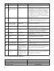
2. Basic High Voltage Information 2-1 High Voltage-Related and 12V-Related Component Locations and Descriptions NOTE: Components with white number in black background are high voltage components.
No. Component Location Description a Traction Motor Under hood Converts three-phase AC power to drive power (torque) which propels the vehicle. b DC/DC Converter – High voltage junction box Under hood This component includes a DC/DC converter and high voltage junction box (J/B). The junction box provides electric power from the Li-ion battery to all high voltage parts of the vehicle.
2-2 High Voltage Safety Measures Circuit insulation The high voltage positive (+) and negative (-) circuits are insulated from the metal chassis. Reducing the risk of electrocution The high voltage components and harnesses have insulated cases or orange-colored coverings which provide insulation and easy identification. The high voltage battery case is electrically connected to the vehicle ground.
2-3 High Voltage Circuit Shut-Off System The high voltage can be shut off by the following methods: Service plug Positioned in the center area of the Li-ion battery, this shuts off output high voltage when manually removed. System main relay Controlled by the power switch, this relay, which is controlled by the 12V system, shuts off the high voltage from the Li-ion battery.
3. Preparation for Dismantling • Failure to properly shut down the high voltage electrical system before the Dismantling Procedures are performed will result in serious injury or death from electrical shock. To prevent serious injury or death, DO NOT touch high voltage harnesses or components without wearing appropriate PPE. • If it is necessary to touch any of the high voltage harnesses or components you must wear appropriate PPE to avoid electrical shock.
4. Apply foot brake and press the ignition switch to turn the system ON. Confirm READY indicator in instrument cluster turns ON. 5. Check Li-ion battery available charge gauge: a. If remaining energy (1) shows higher than half full (7 of 12 gauge lines lit up), continue to next step. b. If remaining energy (2) shows lower than half full (6 of 12 gauge lines lit up), discharging is not needed. 6.
Please contact following number if the Li-ion battery cannot be discharged.
3-3 High Voltage System Shut-Down Procedure Any of the following procedures can shut down the high voltage system. The dismantling operation can only begin after shutting down the high voltage system. If the vehicle is heavily damaged, for example the Li-ion battery is deformed, broken or cracked, appropriate PPE must be used and the Li-ion battery and high voltage components must not be touched.
• If the charge connector is connected to the vehicle, remove it. Refer to 3-3.1 Removing the Charge Connector. • The vehicle contains parts that contain powerful magnets. If a person who is wearing a pacemaker or other medical device is close to these parts, the medical device may be affected by the magnets. Such persons must not perform work on the vehicle. • Be sure to verify that the READY stopped.
3-3.1 Removing the Charge Connector 1. Press the lock release button/lever on the charge connector. NOTE: The quick charge connector is not equipped on all models. 2. Pull the charge connector to remove it. 3-3.2 Indications the High Voltage System is ON 1. If the charge indicator is ON, the high voltage system is active. 2. If the air conditioning remote timer indicator (located on the HVAC controller) is ON, the high voltage system is active. 3.
3-3.4 Primary Procedure indicator status. If it is ON, the high voltage system is active. 1. Check the READY 2. Place the selector lever in the Park (P) position. 3. Press the power switch once to turn OFF the high voltage system. Then verify whether the READY indicator is OFF. 4. If possible, keep the Nissan Intelligent Key™ at least 5 meters (16 feet) away from the vehicle. NOTE: This step is not necessary if the 12V system is already disabled. 5. Disconnect the negative (-) 12V battery cable (1).
3-3.5 Alternate Procedure 1 1. Open the hood. 2. Press and expand the pawls (A) on the sides of the fuse box and remove the fuse box (1) from its housing. NOTE: There is no separate fuse box cover. The bottom of the fuse box is also its cover.
3. Remove the following fuses: a. VCM IGN fuse (F15 VCM IGN 10A) b. F/S1 RLY Fuse (F24 F/S1 RLY 15A) c. VCM Fuse (F3 VCM 20A) 4. If you cannot identify the above fuses, remove all fuses in the fuse box. 5. Disconnect the negative (-) 12V battery cable (1). Insulate the negative (-) battery cable terminal with insulated tape. 6. Wait at least ten (10) minutes for complete discharge of the high voltage capacitor after the fuses are pulled. 7. Perform the dismantling operation.
3-3.6 Alternate Procedure 2 • Do not remove the service plug without wearing appropriate PPE to help protect the dismantler from serious injury or death by electrical shock. • Immediately cover the service plug socket with insulated tape. The Li-ion battery retains high voltage power even when the service plug is removed. To avoid electric shock, DO NOT touch the terminals inside the socket.
4. Wait at least ten (10) minutes for complete discharge of the high voltage capacitor after the service plug has been removed. 5. Open the hood. 6. Disconnect the negative (-) 12V battery cable (1). Insulate the negative (-) battery cable terminal with insulated tape. 7. Perform the dismantling operation. 3-4 Cutting the Vehicle Body • Do not cut into high voltage related areas to avoid severe personal injury or death. • Do not cut into the Li-ion battery to avoid severe personal injury or death.
3-4.1 SRS Air Bag System Components Location The SRS air bag system must not be cut as there is a risk of short circuit and unintentional deployment of the SRS However, the vehicle can be cut (except inflators) under the following conditions: • The front, side and curtain air bags have deployed. • At least three (3) minutes have passed after the 12V battery negative (-) cable has been disconnected and the high voltage system has been shut down. 1. Crash zone sensor 4.
3-4.
3-4.3 Water Submersion Damage level of submerged vehicle may not be apparent. Handling a submerged vehicle without appropriate PPE will result in serious injury or death from electrical shock. • The power switch of the submerged vehicle must be turned OFF first, if possible. Then the vehicle must be completely out of the water and drained to avoid electrical shock.
3-5 Li-ion Battery Damage and Fluid Leaks In cases of battery case breach or electrolyte leakage, contact the fire department immediately. If you must walk away from the vehicle, notify an appropriate responder of the fact that the vehicle is an electric car and contains a high voltage system and warn all others.
4. Jump Starting To start the EV system with a booster battery, the instructions and precautions below must be followed. If done incorrectly, jump starting can lead to a 12V battery explosion, resulting in severe personal injury or death. It could also damage your vehicle. Discharged 12V battery may cause the following issues: • The instrument cluster cannot be displayed while the power switch is turned ON. The start-up sound is not audible. (The electric car system cannot start.
4-1 Jump Starting Procedures 1. If the booster battery is in another vehicle (B), position the two vehicles (A and B) to bring their 12V batteries into close proximity to each other. DO NOT allow the two vehicles to touch. 2. If the LEAF electric parking brake is not applied and the selector lever is not in the P (Park) position, immobilize the vehicle with wheel chocks. 3. Switch off all unnecessary electrical systems (headlights, heater, air conditioner, etc.). 4.
NOTE: If it is not possible to turn the LEAF system ON by following this procedure, contact a NISSAN certified LEAF dealer immediately. 4-2 Electric Parking Brake Mechanical Release Procedure If the electric parking brake cannot be released by operating the parking brake switch, the parking brake can be mechanically released. When releasing the electric parking brake mechanically, always confirm that the vehicle is in the P (Park) position.
4. Open the rear hatch. 5. Remove the electric parking brake mechanical release tool from the tool set that is located in the cargo area. 6. Remove the luggage floor board from the cargo area. 7. Remove the cap by turning it counterclockwise. 8. Insert the tool and turn it counterclockwise while pushing it in. 9. Continue to turn until it stops and then release.
4. Place the selector lever in the N (Neutral) position. 5. Close all doors and press the brake pedal. 6.
NOTE: Insert a screwdriver wrapped with a protective cloth (A) into the slit (1). Pull to remove the fuse box cover (2). Remove the fuse with the fuse puller (3). 7. Release the electrical parking brake. 8. Turn the power switch OFF. 9. Release brake pedal. Be sure to firmly position wheel chocks when P (Park) position is manually released. 4-3.1 Reset Procedure 1. Install the 3 fuses removed previously. 2. Turn the power switch ON and wait 5 seconds without pressing the brake pedal.
4-4 Storing the Vehicle If LEAF needs to be stored or left unattended, the high voltage system must be shut down by removing the service plug (refer to 3–3.6 Alternate Procedure 2) and a sign put on the vehicle indicating it is an electric vehicle with high voltage dangers.
5. Dismantling Information Removal or repair of the high voltage battery requires special tools and specific training. NISSAN strongly recommends that only certified NISSAN dealer technicians perform these operations. 5-1 Precautions for Handling High Voltage Lithium ion (Li-ion) Battery • Because LEAF contains a high voltage (Li-ion) battery, there is the risk of electric shock, electric leakage, or similar accidents if the high voltage components or vehicle is handled incorrectly.
There is the possibility of a malfunction occurring if the vehicle is changed to READY status while the service plug is removed. 5-2 PPE (Personal Protective Equipment) and Insulated Tools 5-2.1 PPE (Personal Protective Equipment) Protective Wear Control Perform an inspection of the PPE items before beginning work. Do not use any damaged PPE items. 5-2.2 Daily Inspection This inspection is performed before and after use.
5-3 Lithium-ion (Li-ion) Battery Pack Removal 5-3.1 Exploded View 1. Bonding plate (Stamp No. 6) 4. Bonding plate (Stamp No. 2) 7. Clip 10. Battery mounting bracket RH 2. Li-ion battery pack 5. Battery under cover (center) 8. Battery under cover (rear) 3. Bonding plate (Stamp No. 4) 6. Battery under cover (front) 9. Battery mounting bracket LH 5-3.2 Removal Procedure 1. Raise the vehicle and remove the battery under covers (front, center and rear). 2.
a. Follow procedure below to disconnect the high voltage connector. Cover battery side of high voltage connector with insulated tape (A). : Insulated tape 3. Disconnect the Li-ion battery vehicle communications connector (A) while turning it counterclockwise. Touching high voltage components without wearing appropriate PPE will cause electrocution. 4. Remove the bonding plates (3 locations). NOTE: The bonding plate (1, 2 and 3) shape differs depending on the location of installation.
5. Remove ONLY the Li-ion battery mounting bolts (A) (6 bolts). At this stage of disassembly, NEVER remove the 4 bolts (B) shown in the illustration. These remaining 4 bolts will retain the Li-ion battery to the vehicle body while the lifter table can be set up in the next step. Touching high voltage components without wearing appropriate PPE will cause electrocution. 6. Set the pallet (1) onto the lifter table (2). • Align the pallet center mark (A) and the lifter center mark (B) (white line).
8. Remove the remaining 4 Li-ion battery mounting bolts (A). Touching high voltage components without wearing appropriate PPE will cause electrocution. 9. Carefully lower the pallet and remove the Li-ion battery (1) from the vehicle. Touching high voltage components without wearing appropriate PPE will cause electrocution. 10. Be sure service plug socket and high voltage connector (battery side) are covered with insulated tape. 11.
6. Recovery/Recycling of the Li-ion High Voltage Battery The Li-ion high voltage battery is fully recyclable. For information regarding safe recovery and recycling of the high voltage battery, please contact the nearest NISSAN dealer.
© 2012 NISSAN NORTH AMERICA, INC. All rights reserved. This document may not be altered without the written permission of NISSAN NORTH AMERICA, INC. Pub. No.