® 2012 PATHFINDER OWNER’S MANUAL For your safety, read carefully and keep in this vehicle.
FOREWORD Welcome to the growing family of new NISSAN owners. This vehicle is delivered to you with confidence. It was produced using the latest techniques and strict quality control. This manual was prepared to help you understand the operation and maintenance of your vehicle so that you may enjoy many miles (kilometers) of driving pleasure. Please read through this manual before operating your vehicle.
WHEN READING THE MANUAL For descriptions specified for four-wheel drive mark is placed at the beginmodels, a ning of the applicable sections/items. As with other vehicles with features for off-road use, failure to operate four-wheel drive models correctly may result in loss of control or an accident. Be sure to read “Driving safety precautions” in the “Starting and driving” section of this manual.
CALIFORNIA PROPOSITION 65 WARNING WARNING APD1005 Engine exhaust, some of its constituents, and certain vehicle components contain or emit chemicals known to the State of California to cause cancer and birth defects or other reproductive harm. In addition, certain fluids contained in vehicles and certain products of component wear contain or emit chemicals known to the State of California to cause cancer and birth defects or other reproductive harm.
XM Radio威 requires subscription, sold separately. Not available in Alaska, Hawaii or Guam. For more information, visit www.xmradio.com. © 2011 NISSAN NORTH AMERICA, INC. All rights reserved. No part of this Owner’s Manual may be reproduced or stored in a retrieval system, or transmitted in any form, or by any means, electronic, mechanical, photocopying, recording or otherwise, without the prior written permission of Nissan North America, Inc.
NISSAN CUSTOMER CARE PROGRAM NISSAN CARES . . . Both NISSAN and your NISSAN dealer are dedicated to serving all your automotive needs. Your satisfaction with your vehicle and your NISSAN dealer are our primary concerns. Your NISSAN dealer is always available to assist you with all your automobile sales and service needs.
Table of Contents Illustrated table of contents 0 Safety—Seats, seat belts and supplemental restraint system 1 Instruments and controls 2 Pre-driving checks and adjustments 3 Monitor, climate, audio, phone and voice recognition systems 4 Starting and driving 5 In case of emergency 6 Appearance and care 7 Maintenance and do-it-yourself 8 Technical and consumer information 9 Index 10
0 Illustrated table of contents Air bags, seat belts and child restraints . . . . . . . . . . . . . . 0-2 Exterior front . . . . . . . . . . . . . . . . . . . . . . . . . . . . . . . . . . . . . . 0-3 Exterior rear. . . . . . . . . . . . . . . . . . . . . . . . . . . . . . . . . . . . . . . 0-4 Passenger compartment . . . . . . . . . . . . . . . . . . . . . . . . . . . 0-5 Instrument panel. . . . . . . . . . . . . . . . . . . . . . . . . . . . . . . . . . . 0-6 Engine compartment check locations . . . . .
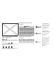
AIR BAGS, SEAT BELTS AND CHILD RESTRAINTS 1. 2. 2nd row seat belts (P. 1-19) Roof-mounted curtain side-impact and rollover supplemental air bag (P. 1-46) 3. Front seat belts (P. 1-19) 4. Head restraints (P.1-7 ) 5. Supplemental front-impact air bags (P.1-46) 6. Seats (P. 1-2) 7. Occupant classification sensor (pressure sensor) (P.1-53) 8. Seat belt with pretensioner (P. 1-59) 9. Front seat-mounted side-impact supplemental air bag (P. 1-46) 10. LATCH (Lower Anchors and Tethers for CHildren) system (P.
EXTERIOR FRONT 1. 2. 3. 4. 5. 6. 7. 8. 9. 10. 11. 12. 13. Engine hood (P. 3-23) Windshield wiper and washer switch (P. 2-26) Windshield (P. 8-22) Power windows (P. 2-45) Door locks, keyfob, keys, NISSAN Intelligent Key ™ (if so equipped) (P. 3-5, 3-2, 3-2, 3-2) Mirrors (P. 3-29) Tire pressure (P. 9-12) Flat tire (P. 6-2) Tire chains (P. 8-43) Replacing bulbs (P. 8-34) Headlight and turn signal switch (P. 2-28) Fog light switch (if so equipped) (P. 2-32) Tow hooks (if so equipped) (P.
EXTERIOR REAR 1. 2. 3. 4. Roof rack (P. 2-44) Vehicle loading (P. 9-13) Glass hatch (P. 3-24) Rear window wiper and washer switch (P.2-27) 5. NISSAN Intelligent Key ™ (if so equipped) (P. 3-2) 6. Glass hatch release (P.3-24) 7. Lift gate release switch (P. 3-23) 8. Replacing bulbs (P. 8-34) 9. Fuel-filler cap, fuel recommendation (P. 3-25, P. 9-4) 10. Fuel-filler door (P. 3-25) 11. Child safety rear door locks (P. 3-7) See the page number indicated in parentheses for operating details.
PASSENGER COMPARTMENT 1. DVD entertainment system (if so equipped) (P. 4-89) 2. Moonroof (if so equipped) (P. 2-48) 3. Map lights (if so equipped) (P. 2-51) 4. Sun visors (P. 3-28) 5. HomeLink姞 universal transceiver (if so equipped) (P. 2-51) 6. Glove box (P. 2-39) 7. Front seats (P. 1-2) 8. 2nd row seats (P.1-16) 9. 3rd row seats (P. 1-18) 10. Cargo area storage (P. 2-42) See the page number indicated in parentheses for operating details.
INSTRUMENT PANEL 1. 2. 3. 4. 5. 6. 7. 8. 9. 10. 11. 12. 13. 14. 15. WIC1490 0-6 Illustrated table of contents Ventilators (P. 4-37) Headlight/fog light (if so equipped)/turn signal switch (P. 2-28) Steering wheel switch for audio control (if so equipped) (P. 4-86) Driver supplemental air bag/horn (P. 1-46, P. 2-33) Meters, gauges and warning/indicator lights (P. 2-3, 2-13) Cruise control main/set switches (P. 5-20) Windshield wiper/washer switch and rear window wiper/washer switch (P. 2-26, P.
. 17. 18. 19. 20. 21. 22. 23. 24. 25. 4WD shift switch (if so equipped) (P. 5-23) Storage (P. 2-37) Front passenger air bag status light (P. 1-55) Climate controls (P. 4-38, 4-45) Hazard warning flasher switch (P. 2-33) Ignition switch (P. 5-10) Tilt steering wheel control (P. 3-27) Heated steering wheel switch (if so equipped) (P. 2-35) Pedal position adjustment switch (if so equipped) (P. 3-27) Outside mirror controls (P.
ENGINE COMPARTMENT CHECK LOCATIONS VQ40DE engine 1. Windshield-washer fluid reservoir (P. 8-15) 2. Fuse/fusible link box (P. 8-25) 3. Fuse and relay box (P. 8-25) 4. Engine oil filler cap (P. 8-10) 5. Engine oil dipstick (P. 8-10) 6. Brake fluid reservoir (P. 8-14) 7. Air cleaner (P. 8-20) 8. Drive belt location (P.8-18) 9. Radiator cap (P. 8-8) 10. Power steering fluid reservoir (P. 8-14) 11. Battery (P. 8-16) 12. Engine coolant reservoir (P.
VK56DE engine 1. Windshield-washer fluid reservoir (P. 8-15) 2. Fuse/fusible link box (P. 8-25) 3. Engine oil dipstick (P. 8-10) 4. Engine oil filler cap (P. 8-10) 5. Brake fluid reservoir (P. 8-14) 6. Air cleaner (P. 8-20) 7. Drive belt location (P. 8-18) 8. Radiator cap (P. 8-8) 9. Power steering fluid reservoir (P. 8-14) 10. Fuse and relay box (P. 8-25) 11. Battery (P. 8-16) 12. Engine coolant reservoir (P. 8-8) See the page number indicated in parentheses for operating details.
WARNING/INDICATOR LIGHTS Warning light or Name Page Anti-lock Braking System (ABS) warning light 2-14 Automatic transmission check warning light 2-14 Automatic transmission oil temperature warning light 2-14 Automatic transmission park warning light ( model) 2-14 Brake warning light 2-15 or 0-10 Illustrated table of contents Warning light Name Page Warning light Name Page Charge warning light 2-16 Seat belt warning light and chime 2-19 Door open warning light 2-16 Shift P warnin
Indicator light Name Page Indicator light Name Page Front passenger air bag status light 2-20 Turn signal/hazard indicator lights 2-22 High beam indicator light (Blue) 2-20 Vehicle dynamic control (VDC) OFF indicator light 2-22 Malfunction indicator light (MIL) 2-20 Overdrive off indicator light (if so equipped) 2-21 Security indicator light 2-21 Slip indicator light 2-21 Transfer 4LO position indicator light ( model) 2-21 Illustrated table of contents 0-11
MEMO 0-12 Illustrated table of contents
1 Safety—Seats, seat belts and supplemental restraint system Seats . . . . . . . . . . . . . . . . . . . . . . . . . . . . . . . . . . . . . . . . . . . . 1-2 Front manual seat adjustment (if so equipped) . . . . . . . . . . . . . . . . . . . . . . . . . . . . . . . . 1-2 Front power seat adjustment (if so equipped) . . . . . . . . . . . . . . . . . . . . . . . . . . . . . . . . 1-4 2nd row bench seat adjustment . . . . . . . . . . . . . . . . . . 1-6 Armrest (if so equipped). . . . . . . . . . . . . . . .
SEATS ● The seatback should not be reclined any more than needed for comfort. Seat belts are most effective when the passenger sits well back and straight up in the seat. If the seatback is reclined, the risk of sliding under the lap belt and being injured is increased. CAUTION When adjusting the seat positions, be sure not to contact any moving parts to avoid possible injuries and/or damage. ARS1152 WARNING ● Do not ride in a moving vehicle when the seatback is reclined. This can be dangerous.
WRS0175 WRS0176 WRS0131 Forward and backward Reclining Seat lifter (driver’s seat) Pull the lever up and hold it while you slide the seat forward or backward to the desired position. Release the lever to lock the seat in position. To recline the seatback, pull the lever up and lean back. To bring the seatback forward, pull the lever up and lean your body forward. Release the lever to lock the seatback in position.
WRS0389 Lumbar support (driver’s seat) The lumbar support feature provides lower back support to the driver. Move the lever up or down to adjust the seat lumbar area. WRS0163 FRONT POWER SEAT ADJUSTMENT (if so equipped) Operating tips ● The power seat motor has an auto-reset overload protection circuit. If the motor stops during operation, wait 30 seconds, then reactivate the switch.
belt fit. See “Precautions on seat belt usage” later in this section. Also, the seatback can be reclined to allow occupants to rest when the vehicle is stopped and the shift selector is in P (Park). WRS0164 WRS0389 Seat lifter (driver’s seat) Lumbar support (driver’s seat) Push the front or rear end of the switch up or down to adjust the angle and height of the seat cushion. The lumbar support feature provides lower back support to the driver. Move the lever up or down to adjust the seat lumbar area.
section. Also, the seatback can be reclined to allow occupants to rest when the vehicle is stopped and the transmission is in P (Park). WARNING ● After adjustment, gently rock in the seat to make sure it is securely locked. LRS2088 Outboard seats 2ND ROW BENCH SEAT ADJUSTMENT Reclining To recline the outboard seatbacks, pull up on the lever and lean back. ● Do not ride in a moving vehicle when the seatback is reclined. This can be dangerous. The shoulder belt will not be against your body.
HEAD RESTRAINTS (1st row only) WARNING LRS0331 2 lift up on the lower corner of the seat Then 䊊 base and tip the outboard seating position of the 2nd row bench seat forward. To exit the 3rd row bench seat, lift up on the same seatback latch and fold the seatback forward onto the seat base. Then lift up on the seat base and tip it forward.
LRS2077 The illustration shows the seating positions equipped with head restraints. The first row head restraints are adjustable. 䉱 Indicates the seating position is equipped with a head restraint. 䡲 Indicates the seating position is equipped with an adjustable headrest. LRS0887 Components 1. Head restraint 2. Adjustment notches 3. Lock knob 4.
LRS0888 To raise the head restraint, pull it up. LRS0889 To lower, push and hold the lock knob and push the head restraint down. LRS0890 Removal Use the following procedure to remove the adjustable head restraints. 1. Pull the head restraint up to the highest position. 2. Push and hold the lock knob. 3. Remove the head restraint from the seat. 4. Store the head restraint properly so it is not loose in the vehicle. 5.
Adjust the Active Head Restraints properly as described in this section. HEAD RESTRAINTS (2nd row – outboard positions only) WARNING LRS0891 Install 1. Align the head restraint stalks with the holes in the seat. Make sure the head restraint is facing the correct direction. The stalk with 1 must be installed the adjustment notches 䊊 2 . in the hole with the lock knob 䊊 2. Push and hold the lock knob and push the head restraint down. 3.
LRS2077 The illustration shows the seating positions equipped with head restraints. The second row head restraints are removable but not adjustable. 䉱 Indicates the seating position is equipped with a head restraint. 䡲 Indicates the seating position is equipped with an adjustable headrest. LRS2073 Components 1. Head restraint 2. Lock knob(s) 3. Stalks LRS2074 Removal Use the following procedure to remove the head restraints. 1. Adjust the seat or seatback as necessary. 2.
ADJUSTABLE HEADREST WARNING LRS2075 Install 1. Align the head restraint stalks with the holes in the seat. Make sure the head restraint is facing the correct direction. 2. Push the head restraint down until it locks in place. The adjustable headrests supplement the other vehicle safety systems. They may provide additional protection against injury in certain rear end collisions. Adjust the headrests properly, as specified in this section. Check the adjustment after someone else uses the seat.
LRS0887 Components 1. Adjustable headrest 2. Adjustment notches WRS0134 LRS0888 To raise the headrest, pull it up. Adjustment Adjust the headrest so the center is level with the center of the seat occupant’s ears. 3. Lock knob 4.
LRS0889 To lower, push and hold the lock knob and push the headrest down. LRS0890 Removal Use the following procedure to remove the adjustable headrests. 1. Pull the headrest up to the highest position. 2. Push and hold the lock knob. 3. Remove the headrest from the seat. 4. Store the headrest properly so it is not loose in the vehicle. 5. Reinstall and properly adjust the headrest before an occupant uses the seating position.
FLEXIBLE SEATING WARNING ● Never allow anyone to ride in the cargo area or on the rear seats when they are in the fold-down position. In a collision, people riding in these areas without proper restraints are more likely to be seriously injured or killed. ● Do not allow people to ride in any area of your vehicle that is not equipped with seats and seat belts. Be sure everyone in your vehicle is in a seat and using a seat belt properly.
WARNING ● If you fold the front passenger’s seatback flat forward to carry longer objects, be sure this cargo is properly secured and not near an air bag. In a crash, an inflating air bag might force that object toward a person. This could cause severe injury or even death. Secure objects away from the area in which an air bag would inflate. See “Precautions on supplemental restraint system” later in this section.
LRS2063 2. Pull the strap to release the head restraint rearward. LRS2099 3 䊊 Then lift up on the recline lever on the side of the outboard seats to fold the outboard seatbacks flat. To fold the center seatback flat, pull up on the strap on the edge of the center seat cushion and fold the seatback toward the front of the vehicle. LRS2068 4 䊊 There is a carpet panel flap on the back of each seat that can be folded toward the back of the vehicle.
8. Rotate the head restraint forward to return it to the normal seating position. WARNING When the seat is returned to the normal seating position, the head restraints must be returned to the upright position to properly protect vehicle occupants. LRS2092 5. The carpet panel flap provides a level cargo floor when the 3rd row seats are also folded flat. 6. To return the outboard 2nd row bench seats to a seating position, reverse the process for the outboard seats. 7.
SEAT BELTS To return the 3rd row seats to a seating position, use the pull straps to raise each seatback. Pull back until the seatbacks latch into position. Make sure to properly raise each seatback to an upright and secured position.
SSS0134 WARNING ● Every person who drives or rides in this vehicle should use a seat belt at all times. Children should be properly restrained in the rear seat and, if appropriate, in a child restraint. 1-20 Safety—Seats, seat belts and supplemental restraint system SSS0016 WARNING ● The seat belt should be properly adjusted to a snug fit. Failure to do so may reduce the effectiveness of the entire restraint system and increase the chance or severity of injury in an accident.
● Be sure the seat belt tongue is securely fastened to the proper buckle. ● Do not wear the seat belt inside out or twisted. Doing so may reduce its effectiveness. ● Do not allow more than one person to use the same seat belt. ● Never carry more people in the vehicle than there are seat belts. SSS0014 WARNING ● Always route the shoulder belt over your shoulder and across your chest. Never put the belt behind your back, under your arm or across your neck.
PREGNANT WOMEN NISSAN recommends that pregnant women use seat belts. The seat belt should be worn snug and always position the lap belt as low as possible around the hips, not the waist. Place the shoulder belt over your shoulder and across your chest. Never run the lap/shoulder belt over your abdominal area. Contact your doctor for specific recommendations. INJURED PERSONS NISSAN recommends that injured persons use seat belts. Check with your doctor for specific recommendations.
The Emergency Locking Retractor (ELR) mode allows the seat belt to extend and retract to allow the driver and passengers some freedom of movement in the seat. The ELR locks the seat belt when the vehicle slows down rapidly or during certain impacts. The Automatic Locking Retractor (ALR) mode (child restraint mode) locks the seat belt for child restraint installation. WRS0137 2 䊊 Slowly pull the seat belt out of the retractor and insert the tongue into the buckle until you hear and feel the latch engage.
To increase your confidence in the seat belts, check the operation as follows: WARNING When fastening the seat belts, be certain that the seatbacks are completely secured in the latched position. If they are not completely secured, passengers may be injured in an accident or sudden stop. ● Grasp the shoulder belt and pull forward quickly. The retractor should lock and restrict further belt movement.
WARNING ● After adjustment, release the adjustment button and try to move the shoulder belt anchor up and down to make sure it is securely fixed in position. ● The shoulder belt anchor height should be adjusted to the position best for you. Failure to do so may reduce the effectiveness of the entire restraint system and increase the chance or severity of injury in an accident.
CHILD SAFETY WARNING ● Only NISSAN seat belt extenders, made by the same company which made the original equipment seat belts, should be used with NISSAN seat belts. ● Adults and children who can use the standard seat belt should not use an extender. Such unnecessary use could result in serious personal injury in the event of an accident. ● Periodically check to see that the seat belt and the metal components, such as buckles, tongues, retractors, flexible wires and anchors, work properly.
WARNING Infants and children need special protection. The vehicle’s seat belts may not fit them properly. The shoulder belt may come too close to the face or neck. The lap belt may not fit over their small hip bones. In an accident, an improperly fitting seat belt could cause serious or fatal injury. Always use appropriate child restraints. All U.S. states and Canadian provinces or territories require the use of approved child restraints for infants and small children.
CHILD RESTRAINTS WARNING Never let a child stand or kneel on any seat and do not allow a child in the cargo area. The child could be seriously injured or killed in a sudden stop or collision.
– Infants and children should never be held on anyone’s lap. Even the strongest adult cannot resist the forces of a collision. – Do not put a seat belt around both a child and another passenger. – NISSAN recommends that all child restraints be installed in the rear seat. Studies show that children are safer when properly restrained in the rear seat than in the front seat.
● If the child restraint is compatible with your vehicle, place your child in the child restraint and check the various adjustments to be sure the child restraint is compatible with your child. Choose a child restraint that is designed for your child’s height and weight. Always follow all recommended procedures. All U.S. states and Canadian provinces or territories require that infants and small children be restrained in an approved child restraint at all times while the vehicle is being operated.
WRS0700 LATCH lower anchor location LRS2091 LATCH lower anchor point locations LATCH lower anchor location The LATCH lower anchors are located at the rear of the seat cushion near the seatback. A label is attached to the seatback to help you locate the LATCH lower anchors.
Top tether anchor WARNING Do not allow cargo to contact the top tether strap when it is attached to the top tether anchor. Properly secure the cargo so it does not contact the top tether strap. Cargo that is not properly secured or cargo that contacts the top tether strap may damage it during a collision. A child could be seriously injured or killed in a collision if the top tether strap is damaged.
REAR-FACING CHILD RESTRAINT INSTALLATION USING LATCH Refer to all Warnings and Cautions in the “Child Safety” and “Child Restraint” sections before installing a child restraint. Follow these steps to install a rear-facing child restraint in the 2nd row seats using the LATCH system: 1. Position the child restraint on the seat. Always follow the child restraint manufacturer’s instructions. WRS0801 Rear-facing web-mounted – step 2 2. Secure the child restraint anchor attachments to the LATCH lower anchors.
5. Check to make sure the child restraint is properly secured prior to each use. If the child restraint is loose, repeat steps 2 through 4. LRS0673 Rear-facing – step 3 3. For child restraints that are equipped with webbing-mounted attachments, remove any additional slack from the anchor attachments. Press downward and rearward firmly in the center of the child restraint with your hand to compress the vehicle seat cushion and seatback while tightening the webbing of the anchor attachments.
WARNING The three-point seat belt with Automatic Locking Retractor (ALR) must be used when installing a child restraint. Failure to use the ALR mode will result in the child restraint not being properly secured. The restraint could tip over or be loose and cause injury to a child in a sudden stop or collision. Also, it can change the operation of the front passenger air bag. See “Front passenger air bag and status light” later in this section.
WRS0761 Rear-facing – step 2 2. Route the seat belt tongue through the child restraint and insert it into the buckle until you hear and feel the latch engage. Be sure to follow the child restraint manufacturer’s instructions for belt routing. LRS0669 Rear-facing – step 3 3. Pull the shoulder belt until the belt is fully extended. At this time, the seat belt retractor is in the Automatic Locking Retractor (ALR) mode (child restraint mode).
7. Check to make sure that the child restraint is properly secured prior to each use. If the seat belt is not locked, repeat steps 1 through 6. After the child restraint is removed and the seat belt fully retracted, the ALR mode (child restraint mode) is canceled. FORWARD-FACING CHILD RESTRAINT INSTALLATION USING LATCH WRS0762 Rear-facing – step 5 5.
WRS0799 Forward-facing web-mounted – step 2 2. Secure the child restraint anchor attachments to the LATCH lower anchors. Check to make sure the LATCH attachment is properly attached to the lower anchors. If the child restraint is equipped with a top tether strap, route the top tether strap and secure the tether strap to the tether anchor point. See “Installing top tether strap” in this section.
7. Check to make sure the child restraint is properly secured prior to each use. If the child restraint is loose, repeat steps 3 through 6. FORWARD-FACING CHILD RESTRAINT INSTALLATION USING THE SEAT BELTS WARNING WRS0697 Forward-facing – step 6 6. After attaching the child restraint, test it before you place the child in it. Push it from side to side while holding the child restraint near the LATCH attachment path. The child restraint should not move more than 1 inch (25 mm), from side to side.
2. Position the child restraint on the seat. Always follow the child restraint manufacturer’s instructions. The back of the child restraint should be secured against the vehicle seatback. If necessary, adjust or remove the head restraint to obtain the correct child restraint fit. If the head restraint is removed, store it in a secure place. Be sure to reinstall the head restraint when the child restraint is removed.
LRS0668 Forward-facing – step 5 5. Allow the seat belt to retract. Pull up on the shoulder belt to remove any slack in the belt. WRS0681 Forward-facing – step 6 6. Remove any additional slack from the seat belt; press downward and rearward firmly in the center of the child restraint with your knee to compress the vehicle seat cushion and seatback while pulling up on the seat belt. 7. Tighten the tether strap according to the manufacturer’s instructions to remove any slack.
9. Check to make sure the child restraint is properly secured prior to each use. If the seat belt is not locked, repeat steps 2 through 8. WRS0475 Forward-facing – step 10 10. If the child restraint is installed in the front passenger seat, place the ignition switch in the ON position. The front passenger air bag should illuminate. If this status light light is not illuminated see “Front passenger air bag and status light” in this section. Move the child restraint to another seating position.
2. Secure the tether strap to the tether anchor 2 on the seat directly behind the child point 䊊 restraint. 3. Refer to the appropriate child restraint installation procedure steps in this section before tightening the tether strap. If you have any questions when installing a top tether strap, consult your NISSAN dealer for details.
● Make sure the child’s head will be properly supported by the booster seat or vehicle seat. The seatback must be at or above the center of the child’s ears. For example, if a 1 is chosen, the low back booster seat 䊊 vehicle seatback must be at or above the center of the child’s ears. If the seatback is lower than the center of the child’s ears, a 2 should be used. high back booster seat 䊊 LRS0464 Booster seats of various sizes are offered by several manufacturers.
If the seating position does not have an adjustable head restraint and it is interfering with the proper booster seat fit, try another seating position or a different booster seat. 4. Position the lap portion of the seat belt low and snug on the child’s hips. Be sure to follow the booster seat manufacturer’s instructions for adjusting the seat belt routing. WRS0699 LRS0454 1. If you must install a booster seat in the front seat, move the seat to the rearmost position. Front passenger position 3.
SUPPLEMENTAL RESTRAINT SYSTEM PRECAUTIONS ON SUPPLEMENTAL RESTRAINT SYSTEM This Supplemental Restraint System (SRS) section contains important information concerning the following systems: ● Driver and passenger supplemental frontimpact air bag (NISSAN Advanced Air Bag System) ● Front seat-mounted side-impact supplemental air bag WRS0475 7. If the booster seat is installed in the front passenger seat, place the ignition switch in the ON position.
● The driver and front passenger seat belt buckles are equipped with sensors that detect if the seat belts are fastened. The Advanced Air Bag System monitors the severity of a collision and seat belt usage then inflates the air bags as needed. Failure to properly wear seat belts can increase the risk or severity of injury in an accident. WRS0031 WARNING ● The front air bags ordinarily will not inflate in the event of a side impact, rear impact, rollover, or lower severity frontal collision.
ARS1133 ARS1041 WARNING ● Never let children ride unrestrained or extend their hands or face out of the window. Do not attempt to hold them in your lap or arms. Some examples of dangerous riding positions are shown in the illustrations.
ARS1042 ARS1043 ARS1044 WARNING ● Children may be severely injured or killed when the front air bags, side air bags or curtain and rollover air bags inflate if they are not properly restrained. Pre-teens and children should be properly restrained in the rear seat, if possible.
ARS1045 WRS0431 WRS0256 WARNING ● Even with the NISSAN Advanced Air Bag System, never install a rear-facing child restraint in the front seat. An inflating front air bag could seriously injure or kill your child. See “Child restraints” earlier in this section for details. 1-50 Safety—Seats, seat belts and supplemental restraint system Do not lean against doors or windows.
WARNING WRS0365 Do not lean against doors or windows. SSS0162 Do not lean against doors or windows. ● The seat belts, the side air bags and curtain and rollover air bags are most effective when you are sitting well back and upright in the seat. The side air bag and curtain and rollover air bag inflate with great force. Do not allow anyone to place their hand, leg or face near the side air bag on the side of the seatback of the front seat or near the side roof rails.
WRS0363 WARNING ● When sitting in the 2nd row rear seat, do not hold onto the seatback of the front seat. If the side air bag inflates, you may be seriously injured. Be especially careful with children, who should always be properly restrained. Some examples of dangerous riding positions are shown in the illustrations. ● Do not use seat covers on the front seatbacks. They may interfere with side air bag inflation.
1. Roof-mounted curtain side-impact and rollover supplemental air bag inflators 2. Roof-mounted curtain side-impact and rollover supplemental air bags 3. Air bag Control Unit (ACU) 4. Supplemental front-impact air bag modules 5. Crash zone sensor 6. Occupant classification system control unit 7. Occupant classification sensor (pressure sensor) 8. Satellite sensors 9. Seat belt buckle switches 10. Seat belt with pretensioner 11.
The driver supplemental front-impact air bag is located in the center of the steering wheel. The passenger supplemental front-impact air bag is mounted in the dashboard above the glove box. The front air bags are designed to inflate in higher severity frontal collisions, although they may inflate if the forces in another type of collision are similar to those of a higher severity frontal impact. They may not inflate in certain frontal collisions.
Status light is The front passenger air bag status light located near the climate controls. After the ignition switch is placed in the ⬙ON⬙ position, the front passenger air bag status light on the instrument panel illuminates for about 7 seconds and then turns off or remains illuminated depending on the front passenger seat occupied status. The light operates as follows: is ● Unoccupied passenger’s seat: The OFF and the front passenger air bag is OFF and will not inflate in a crash.
classification sensor and the belt tension detected on the seat belt, the Advanced Air Bag System determines whether the front passenger air bag should be automatically turned OFF as required by the regulations. Front passenger seat adult occupants who are properly seated and using the seat belt as outlined in this manual should not cause the passenger air bag to be automatically turned OFF.
If a malfunction occurs in the front passenger air bag system, the supplemental air bag warning , located in the meter and gauges area light of the instrument panel, will blink. Have the system checked by a NISSAN dealer. ● Do not make unauthorized changes to your vehicle’s electrical system, suspension system or front end structure. This could affect proper operation of the front air bag system.
severity side collisions, although they may inflate if the forces in another type of collision are similar to those of a higher severity side impact. They are designed to inflate on the side where the vehicle is impacted. They may not inflate in certain side collisions. Curtain and rollover air bags are also designed to inflate in certain types of rollover collisions or near rollovers.
WARNING ● Do not place any objects near the seatback of the front seats. Also, do not place any objects (an umbrella, bag, etc.) between the front door finisher and the front seat. Such objects may become dangerous projectiles and cause injury if a side air bag inflates. ● Right after inflation, several side air bag and curtain and rollover air bag system components will be hot. Do not touch them; you may severely burn yourself.
● If you need to dispose of a pretensioner or scrap the vehicle, contact a NISSAN dealer. Incorrect disposal procedures could cause personal injury. Working with the seat belt retractor, the pretensioner helps tighten the seat belt when the vehicle becomes involved in certain types of collisions, helping to restrain front seat occupants. The pretensioner is encased with the seat belt retractor. These seat belts are used the same way as conventional seat belts.
If any of the following conditions occur, the front air bag, side air bag, curtain and rollover air bag and pretensioner systems need servicing: ● The supplemental air bag warning light remains on after approximately 7 seconds. ● The supplemental air bag warning light flashes intermittently. ● The supplemental air bag warning light does not come on at all.
WARNING ● Once a front air bag, side air bag, or curtain and rollover air bag has inflated, the air bag module will not function again and must be replaced. Additionally, the activated pretensioners must also be replaced. The air bag module and pretensioner should be replaced by a NISSAN dealer. The air bag module and pretensioner cannot be repaired.
MEMO Safety—Seats, seat belts and supplemental restraint system 1-63
2 Instruments and controls Instrument panel. . . . . . . . . . . . . . . . . . . . . . . . . . . . . . . . . . . 2-2 Meters and gauges . . . . . . . . . . . . . . . . . . . . . . . . . . . . . . . . 2-3 Speedometer and odometer . . . . . . . . . . . . . . . . . . . . . 2-4 Tachometer . . . . . . . . . . . . . . . . . . . . . . . . . . . . . . . . . . . . 2-6 Engine coolant temperature gauge . . . . . . . . . . . . . . . 2-6 Fuel gauge . . . . . . . . . . . . . . . . . . . . . . . . . . . . . . . . . . . .
Cup holders . . . . . . . . . . . . . . . . . . . . . . . . . . . . . . . . . . 2-40 Cargo area storage . . . . . . . . . . . . . . . . . . . . . . . . . . . . 2-42 Luggage hooks. . . . . . . . . . . . . . . . . . . . . . . . . . . . . . . . 2-42 Roof rack . . . . . . . . . . . . . . . . . . . . . . . . . . . . . . . . . . . . . 2-44 Windows . . . . . . . . . . . . . . . . . . . . . . . . . . . . . . . . . . . . . . . . 2-45 Power windows . . . . . . . . . . . . . . . . . . . . . . . . . . . . . . .
INSTRUMENT PANEL 1. 2. 3. 4. 5. 6. 7. 8. 9. 10. 11. 12. 13. 14. 15. WIC1490 2-2 Instruments and controls Ventilators (P. 4-37) Headlight/fog light (if so equipped)/turn signal switch (P. 2-28) Steering wheel switch for audio control (if so equipped) (P. 4-86) Driver supplemental air bag/horn (P. 1-46, P. 2-33) Meters, gauges and warning/indicator lights (P. 2-3, 2-13) Cruise control main/set switches (P. 5-20) Windshield wiper/washer switch and rear window wiper/washer switch (P. 2-26, P.
METERS AND GAUGES 16. 17. 18. 19. 20. 21. 22. 23. 24. 25. 4WD shift switch (if so equipped) (P. 5-23) Storage (P. 2-37) Front passenger air bag status light (P. 1-55) Climate controls (P. 4-38, 4-45) Hazard warning flasher switch (P. 2-33) Ignition switch (P. 5-10) Tilt steering wheel control (P. 3-27) Heated steering wheel switch (if so equipped) (P. 2-35) Pedal position adjustment switch (if so equipped) (P. 3-27) Outside mirror controls (P.
Resetting the trip odometer: Pushing the change button for more than 1 second resets the currently displayed trip odometer to zero. LIC2029 1. 2. 3. Speedometer Odometer Change button SPEEDOMETER AND ODOMETER Speedometer The speedometer indicates vehicle speed.
LRS2004 Loose fuel cap warning message A for more than 1 second Press the reset button 䊊 to reset the LOOSE FUEL CAP warning message after the fuel cap has been tightened. For additional information see “Fuel-filler cap” in the “Pre-driving checks and adjustments” section. LIC2017 A for more than 1 second Push the reset button 䊊 to turn off the CHECK TIRE PRES warning message. The low tire pressure warning light remains illuminated until the tires are inflated to the recommended COLD tire pressure.
CAUTION If the gauge indicates coolant temperature near the hot (H) end of the normal range, reduce vehicle speed to decrease temperature. If the gauge is over the normal range, stop the vehicle as soon as safely possible. If the engine is overheated, continued operation of the vehicle may seriously damage the engine. See “If your vehicle overheats” in the “In case of emergency” section for immediate action required. LIC0738 TACHOMETER The tachometer indicates engine speed in revolutions per minute (rpm).
indicates that the fuel-filler door is The located on the driver’s side of the vehicle. CAUTION ● If the vehicle runs out of fuel, the Malfunction Indicator Light (MIL) may come on. Refuel as soon as possible. light After a few driving trips. the should turn off. If the light remains on after a few driving trips, have the vehicle inspected by a NISSAN dealer. LIC0740 ● For additional information, see “Malfunction Indicator Light (MIL)” later in this section.
TRIP COMPUTER ● If the gauge needle does not move with the proper amount of engine oil, have the vehicle checked by a NISSAN dealer. Continued vehicle operation in such a condition could cause serious damage to the engine. The display of the trip computer is situated in the speedometer display. When the ignition switch is placed in the ON position, the display scrolls all the modes of the trip computer and then shows the mode chosen before the ignition switch was placed in the OFF position.
COMPASS DISPLAY (if so equipped) When the fuel level drops even lower, the dte display will change to (----). Average fuel consumption (Mpg or l/100km) This unit measures terrestrial magnetism and indicates the heading direction of the vehicle. NOTE: With the ignition switch in the ON position, press ● If the amount of fuel added while the ignition switch is OFF is small, the display just before the ignition switch is turned OFF may continue to be displayed.
For information about the automatic anti-glare feature, refer to “Automatic anti-glare rearview mirror” in the “Pre-driving checks and adjustments” section. WIC0904 Type A COMPASS DISPLAY Push the or button for about 1 second when the ignition switch is placed in the ON position to toggle the compass direction display 1 on or off. The display will indicate the direction 䊊 that the vehicle is heading.
Zone variation change procedure The difference between magnetic north and geographical north is known as variance. In some areas, this difference can sometimes be great enough to cause false compass readings. Follow these instructions to set the variance for your particular location if this happens: button for about 1. Press and hold the button for about 8 11 seconds or the seconds. The current zone number will appear in the display. Release the button. 2. Find your current location on the zone map.
1. With the display turned on, press and hold the button for about 13 seconds or the for about 10 seconds. The “C” or “CAL” icon in the compass display will illuminate. 2. Calibrate the compass by driving the vehicle in three complete circles at a maximum speed of 5 MPH (8 km/h). 3. After completing the circles, the display should return to normal. CAUTION ● Do not install a ski rack, antenna, etc., which are attached to the vehicle by means of a magnet. They affect the operation of the compass.
WARNING/INDICATOR LIGHTS AND AUDIBLE REMINDERS Low tire pressure warning light Front passenger air bag status light Automatic Transmission check warning light Low windshield-washer fluid warning light High beam indicator light (Blue) Automatic transmission oil temperature warning light NISSAN Intelligent Key™ warning light (if so equipped) Malfunction indicator light (MIL) Automatic transmission park warning light model) ( Seat belt warning light and chime Overdrive off indicator light (if so equ
CHECKING BULBS With all doors closed, apply the parking brake and place the ignition switch in the ON position without starting the engine. The following lights will come on: , or , , , , The following lights come on briefly and then go off: or , , , , , , , , , , If any light fails to come on, it may indicate an open circuit in the electrical system. Have the system repaired promptly.
● Part time 4WD: Shift the 4WD switch into the 2WD, 4H or 4LO position again to turn off the ATP warning light when the shift selector is in the P position and the ATP warning light is ON. (Before shifting the 4WD switch into the 4LO position, move the shift selector into the N position once, shift the shift selector into P again and make sure the ATP warning light is OFF.
Charge warning light If this light comes on while the engine is running, it may indicate the charging system is not functioning properly. Turn the engine off and check the generator belt. If the belt is loose, broken, missing, or if the light remains on, see a NISSAN dealer immediately. CAUTION ● Do not ground electrical accessories directly to the battery terminal. Doing so will bypass the variable control system and the vehicle battery may not charge completely.
● If the warning light is still on after the above operation, have your vehicle checked by a NISSAN dealer as soon as possible. Low fuel warning light This light comes on when the fuel level in the fuel tank is getting low. Refuel as soon as it is convenient, preferably before the fuel gauge reaches E (Empty). There will be a small reserve of fuel in the tank when the fuel gauge needle reaches E (Empty).
WARNING ● If the light does not illuminate with the ignition switch placed in the ON position, have the vehicle checked by a NISSAN dealer as soon as possible. ● If the light illuminates while driving, avoid sudden steering maneuvers or abrupt braking, reduce vehicle speed, pull off the road to a safe location and stop the vehicle as soon as possible. Driving with under-inflated tires may permanently damage the tires and increase the likelihood of tire failure.
Seat belt warning light and chime The light and chime remind you to fasten your seat belts. The light illuminates whenever the ignition switch is placed in the ON or START position and remains illuminated until the driver’s seat belt is fastened. At the same time, the chime sounds for about 6 seconds unless the driver’s seat belt is securely fastened. The seat belt warning light may also illuminate if the front passenger’s seat belt is not fastened when the front passenger’s seat is occupied .
Cruise set switch indicator light The light comes on while the vehicle speed is controlled by the cruise control system. If the light blinks while the engine is running, it may indicate the cruise control system is not functioning properly. Have the system checked by a NISSAN dealer. 4WD shift indicator light model) ( The light should turn off within 1 second after placing the ignition switch in the ON position.
● Malfunction Indicator Light blinking — An engine misfire has been detected which may damage the emission control system. To reduce or avoid emission control system damage: This light comes on when the overdrive function is OFF. The light should turn off within 1 second after placing the ignition switch in the ON position. – do not drive at speeds above 45 MPH (72 km/h). The automatic transmission overdrive function is controlled by the overdrive switch. – avoid hard acceleration or deceleration.
You cannot move the transfer 4WD shift switch between 4H and 4LO unless you stop the vehicle and shift the shift selector to the N position with the brake pedal depressed. Part time 4WD (if so equipped) The 4LO indicator light must stop blinking and remain illuminated or turn off before shifting the transmission into gear. If the shift selector is shifted from the N position to any other gear when the 4LO indicator light is blinking, the vehicle may move unexpectedly.
SECURITY SYSTEMS The system helps deter vehicle theft but cannot prevent it, nor can it prevent the theft of interior or exterior vehicle components in all situations. Always secure your vehicle even if parking for a brief period. Never leave your keys in the ignition, and always lock the vehicle when unattended. Be aware of your surroundings, and park in secure, well-lit areas whenever possible.
3. Close all doors. Lock all doors. The doors can be locked with: ● the power door lock switch (if the door is opened, locked and then closed). ● the key — master or mechanical (Intelligent Key models). ● any request switch (Intelligent Key models). ● the keyfob or Intelligent Key. Keyfob and Intelligent Key operation: button. All doors lock. ● Push the The hazard lights flash twice and the horn beeps once to indicate all doors are locked.
NISSAN VEHICLE IMMOBILIZER SYSTEM The NISSAN Vehicle Immobilizer System will not allow the engine to start without the use of a registered key. If the engine fails to start using a registered key (for example, when interference is caused by another registered key, an automated toll road device or automatic payment device on the key ring), restart the engine using the following procedures: 1. Leave the ignition switch placed in the ON position for approximately 5 seconds. 2.
WINDSHIELD WIPER AND WASHER SWITCH NOTE: CAUTION You can turn on or turn off the driving speed dependent intermittent wiper function for vehicles with navigation system. Refer to “Comfort & Convenience settings” in the “Monitor, climate, audio, phone and voice recognition systems” section later in this manual. 2 䊊 3 䊊 WIC0843 SWITCH OPERATION The windshield wiper and washer operates when the ignition switch is placed in the ON position.
REAR WINDOW WIPER AND WASHER SWITCH REAR WINDOW AND OUTSIDE MIRROR (if so equipped) DEFROSTER SWITCH WARNING In freezing temperatures the washer solution may freeze on the window and obscure your vision. Warm the rear window with the defroster before you wash the rear window. CAUTION ● Do not operate the washer continuously for more than 30 seconds. WIC0844 The rear window wiper and washer operate when the ignition switch is placed in the ON position.
HEADLIGHT AND TURN SIGNAL SWITCH LIC1173 Type B 2-28 Instruments and controls LIC0560 Type A LIC0687 Type B
CAUTION Use the headlights with the engine running to avoid discharging the vehicle battery. LIC0688 Type C HEADLIGHT CONTROL SWITCH Lighting 1 䊊 2 䊊 LIC0561 Autolight system (if so equipped) The autolight system allows the headlights to be set so they turn on and off automatically. The autolight system can: When turning the switch to the position, the front parking, tail, license plate and instrument panel lights come on.
To turn on the autolight system: 1. Turn the headlight switch to the AUTO posi1 . tion 䊊 2. Place the ignition switch in the ON position. 3. The autolight system automatically turns the headlights on and off. Initially, if the ignition switch is placed in the OFF position and a door is opened and left open, the headlights remain ON for a period of time. If another door is opened while the headlights are on, then the timer is reset. To turn the autolight system off, turn the switch to , or position.
Battery saver system If the ignition switch is placed in the OFF position while the headlight switch is in the or position, the headlights will turn off after a period of time. After the headlights automatically turn off with the or position, headlight switch in the the headlights will illuminate again if the headlight switch is moved to the OFF position and then or position.
The headlights must be on and the low beams selected for the fog lights to operate. The fog lights automatically turn off when the high beam headlights are selected. LIC0563 LIC0393 TURN SIGNAL SWITCH FOG LIGHT SWITCH (if so equipped) Turn signal To turn the fog lights on, turn the headlight switch to the position, then turn the fog light switch to the position. 1 䊊 Move the lever up or down to signal the turning direction. When the turn is completed, the turn signals cancel automatically.
HAZARD WARNING FLASHER SWITCH HORN The flashers will operate with the ignition switch placed in any position. Some state laws may prohibit the use of the hazard warning flasher switch while driving. LIC0394 WIC1449 Push the switch on to warn other drivers when you must stop or park under emergency conditions. All turn signal lights flash. To sound the horn, push the area between the horn icons on the steering wheel.
HEATED SEAT (if so equipped) WARNING Do not use or allow occupants to use the seat heater if you or the occupants cannot monitor elevated seat temperatures or have an inability to feel pain in body parts that contact the seat. Use of the seat heater by such people could result in serious injury. CAUTION LIC1041 The front seats are warmed by built-in heaters. 1. Start the engine. 2. Push the LO or HI position of the switch, as desired, depending on the temperature.
HEATED STEERING WHEEL (if so equipped) VEHICLE DYNAMIC CONTROL (VDC) OFF SWITCH NOTE: If the surface temperature of the steering wheel is above 68°F (20°C) when the switch is turned on, the system will not heat the steering wheel. This is not a malfunction. LIC0421 LIC1548 The heated steering wheel system is designed to operate only when the surface temperature of the steering wheel is below 68°F (20°C).
POWER OUTLET WIC1268 Front row The power outlets are for powering electrical accessories such as cellular telephones. The bottom power outlet located on instrument panel and the power outlet located in the cargo area are powered directly by the vehicle’s battery. The top power outlet located on the instrument panel and the power outlet located inside the center console are powered only when the ignition switch is placed in the ACC or ON position. Open the cap to use a power outlet.
STORAGE ● Push the plug in as far as it will go. If good contact is not made, the plug may overheat or the internal temperature fuse may open. ● When not in use, be sure to close the cap. Do not allow water or any other liquids to contact the outlet. LIC1539 Top center tray (if so equipped) WIC1269 Bottom center tray STORAGE TRAYS WARNING Do not place sharp objects in the trays to help prevent injury in an accident or sudden stop.
WIC0830 Right-hand side 3rd row tray WIC1270 Front row bin STORAGE BINS 2-38 Instruments and controls LIC0766 CONSOLE BOX 1 to open the console box lid Pull up on the lever 䊊 2 .
CAUTION ● Do not use for anything other than sunglasses. ● Do not leave sunglasses in the sunglasses holder while parking in direct sunlight. The heat may damage the sunglasses. LIC0768 WIC0673 GLOVE BOX SUNGLASSES HOLDER To open the top portion of the glove box, push the A up and raise the lid. latch 䊊 To open the sunglasses holder, push and release. To open the lower portion of the glove box, pull B down and lower the lid. the handle 䊊 Use the master key to lock or unlock the glove box.
LIC0772 MAP POCKETS WIC1271 LIC0575 Front SEAT POCKETS A pocket is located on the back of the driver’s seat. CUP HOLDERS The front cup holders have adapters that can be removed to accommodate larger cups. WARNING The cup holder should not be used while driving so full attention may be given to vehicle operation.
CAUTION ● Avoid abrupt starting and braking when the cup holder is being used to prevent spilling the drink. If the liquid is hot, it can scald you or your passenger. ● Use only soft cups in the cup holder. Hard objects can injure you in an accident. WIC0771 2nd row (rear of front console) To open the 2nd row cup holders (rear of the front console), lower the lid. To close, raise the lid. If stepped on, the cup holder is designed to snap loose from the console.
LIC0774 3rd row — Type B LIC0784 Bottle holder CAUTION ● Do not use bottle holder for any other objects that could be thrown about in the vehicle and possibly injure people during sudden braking or an accident. ● Do not use bottle holder for open liquid containers. 2-42 Instruments and controls LIC0777 CARGO AREA STORAGE 1 To access the floor storage area, push down 䊊 2 to raise the handle, then pull up on the handle 䊊 to lift the luggage board.
WARNING ● Properly secure all cargo with ropes or straps to help prevent it from sliding or shifting. Do not place cargo higher than the seatbacks. In a sudden stop or collision, unsecured cargo could cause personal injury. ● Use suitable ropes and hooks to secure cargo. ● Never allow anyone to ride in the luggage area. It is extremely dangerous to ride in a cargo area inside of a vehicle. In a collision, people riding in these areas are more likely to be seriously injured or killed.
WARNING ● Drive extra carefully when the vehicle is loaded at or near the cargo carrying capacity, especially if the significant portion of that load is carried on the roof rack. ● Heavy loading of the roof rack has the potential to affect the vehicle stability and handling during sudden or abnormal handling maneuvers. ● Roof rack load should be evenly distributed. ● Do not exceed maximum roof rack load weight capacity.
WINDOWS Be careful that your vehicle does not exceed the Gross Vehicle Weight Rating (GVWR) or its Gross Axle Weight Rating (GAWR front and rear). The GVWR and GAWR are located on the F.M.V.S.S. label (located on the driver’s door pillar). For more information regarding GVWR and GAWR, refer to “Vehicle loading information” in the “Technical and consumer information” section later in this manual. The front and rear cross bars (if so equipped) can be adjusted or removed. To adjust: A on 1.
Driver’s side power window switch The driver’s side control panel is equipped with switches to open or close the front and rear passenger windows. To open a window, push the switch and hold it down. To close a window, pull the switch and hold it up. To stop the opening or closing function at any time, simply release the switch. WIC1124 1. 2. 3. 4. 5. 6.
Auto-reverse function The auto-reverse function can be activated when a window is closed by automatic operation, when the ignition switch is placed in the ON position or for a period of time after the ignition switch is placed in the OFF position. If the control unit detects something caught in a window equipped with automatic operation as it is closing, the window will be immediately lowered.
MOONROOF (if so equipped) To open or close the moonroof part way, push the switch in any direction while the moonroof is sliding to stop it in the desired position. Tilting the moonroof Close the moonroof by pushing the switch to2 . Release the switch, then ward UP/CLOSE 䊊 push the UP/CLOSE switch again to tilt the moonroof up. To tilt the moonroof down, push the switch to1 .
INTERIOR LIGHTS (if so equipped) When tilting down: Sunshade If the control unit detects something caught in the moonroof as it tilts down, the moonroof will immediately tilt up. Open and close the sunshade by sliding it forward or backward. If the auto-reverse function malfunctions and repeats opening or tilting up the moonroof, keep pushing the tilt down switch within 5 seconds after it happens; the moonroof will fully close gradually. Make sure nothing is caught in the moonroof.
PERSONAL LIGHTS (if so equipped) The lights will turn off while the timer is activated when: ● The driver’s door is locked by the keyfob, a key, or the power door lock switch. ● The ignition switch is placed in the ON position. The lights will turn off automatically after a period of time while doors are open to prevent the battery from becoming discharged. 3 , the When the switch is in the OFF position 䊊 interior lights do not illuminate, regardless of door position.
MAP LIGHTS CARGO LIGHT HOMELINK姞 UNIVERSAL TRANSCEIVER (if so equipped) The HomeLink姞 Universal Transceiver provides a convenient way to consolidate the functions of up to three individual hand-held transmitters into one built-in device. HomeLink姞 Universal Transceiver: ● Will operate most Radio Frequency (RF) devices such as garage doors, gates, home and office lighting, entry door locks and security systems. LIC0791 LIC0590 To turn the map lights on, press the switches.
WARNING ● Do not use the HomeLink姞 Universal Transceiver with any garage door opener that lacks safety stop and reverse features as required by federal safety standards. (These standards became effective for opener models manufactured after April 1, 1982). A garage door opener which cannot detect an object in the path of a closing garage door and then automatically stop and reverse, does not meet current federal safety standards.
grammed device, press and hold the programmed HomeLink姞 button — releasing when the device begins to activate. 5. If the indicator light on the HomeLink姞 blinks rapidly for 2 seconds and then turns solid, HomeLink姞 has picked up a “rolling code” garage door opener signal. You will need to proceed with the next steps to train the HomeLink姞 to complete the programming which may require a ladder and another person for convenience. 6.
● position the hand-held transmitter 1 - 3 inches (26 - 76 mm) away from the HomeLink姞 surface. Hold the transmitter in that position for up to 15 seconds. If HomeLink姞 is not programmed within that time, try holding the transmitter in another position – keeping the indicator light in view at all times. If you continue to have programming difficulties, please contact the NISSAN Consumer Affairs Department. The phone numbers are located in the Foreword of this manual.
3 Pre-driving checks and adjustments Keys . . . . . . . . . . . . . . . . . . . . . . . . . . . . . . . . . . . . . . . . . . . . . 3-2 NISSAN Intelligent Key™ (if so equipped) . . . . . . . . . 3-2 NISSAN Vehicle Immobilizer System keys . . . . . . . . . 3-4 Doors . . . . . . . . . . . . . . . . . . . . . . . . . . . . . . . . . . . . . . . . . . . . 3-5 Locking with key. . . . . . . . . . . . . . . . . . . . . . . . . . . . . . . . 3-5 Locking with inside lock knob . . . . . . . . . . . . . . . . . . . .
KEYS A key number is only necessary when you have lost all keys and do not have one to duplicate from. If you still have a key, your NISSAN dealer can duplicate it. WPD0128 1. 2. 3. 4. Two master keys (black) with transponder chip and chrome NISSAN brand symbol on one side Valet key (black) with transponder chip Key number plate Transponder chip A key number plate is supplied with your keys. Record the key number and keep it in a safe place (such as your wallet), not in the vehicle.
As many as 4 Intelligent Keys can be registered and used with one vehicle. The new keys must be registered by a NISSAN dealer prior to use with the Intelligent Key and NISSAN Vehicle Immobilizer System of your vehicle. Since the registration process requires erasing all memory in the Intelligent Key components when registering new keys, be sure to take all Intelligent Keys that you have to the NISSAN dealer.
CAUTION Always carry the mechanical key installed in the Intelligent Key slot. See “Doors” in this section and “Storage” in the “Instruments and controls” section of this manual. Valet hand-off When you have to leave a key with a valet, give them the Intelligent Key itself and keep the mechanical key with you to protect your belongings. To prevent the glove box or console box from being opened during valet hand-off, follow the procedure below. 1. Remove the mechanical key from the Intelligent Key. 2.
DOORS When the doors are locked using one of the following methods, the doors can not be opened using the inside or outside door handles. The doors must be unlocked to open the doors. Opening and closing windows The driver’s door key operation allows you to open and close windows equipped with automatic operation at the same time. ● To open the windows, turn the driver’s door key toward the rear of the vehicle for longer than 1 second after the door is unlocked.
Lockout protection When the power door lock switch (driver’s or front passenger’s side) is moved to the lock position with the key in the ignition switch and any door open, all doors will lock and then unlock automatically. This helps to prevent the keys from being accidently locked inside the vehicle. AUTOMATIC DOOR LOCKS ● All doors lock automatically when the vehicle speed reaches 15 MPH (24 km/h).
REMOTE KEYLESS ENTRY SYSTEM (if so equipped) 4. When activated, the hazard indicator will flash twice. When deactivated, the hazard indicator will flash once. WARNING Radio waves could adversely affect electric medical equipment. Those who use a pacemaker should contact the electric medical equipment manufacturer for the possible influences before use. 5. The ignition switch must be placed in the OFF and ON position again between each setting change.
The keyfob can operate at a maximum distance of approximately 33 ft (10 m) from the vehicle. The effective distance depends upon the conditions around the vehicle. ● Do not change or modify the keyfob. As many as 5 keyfobs can be used with one vehicle. For information concerning the purchase and use of additional keyfobs, contact a NISSAN dealer. ● Do not place the keyfob for an extended period in an area where temperatures exceed 140°F (60°C).
● When the button is pressed with all doors locked, the hazard warning lights flash twice and the horn beeps once as a reminder that the doors are already locked. button on the keyfob again Press the within 5 seconds. ● All doors unlock. ● The hazard warning lights flash once if all doors are completely closed.
Opening windows Using the interior lights The keyfob allows you to open windows equipped with automatic operation simultaneously. Press the button on the keyfob once to turn on the interior lights. For additional information, refer to “Interior lights” in the “Instruments and controls” section in this manual. but● To open the windows, press the ton on the keyfob for longer than 3 seconds after all doors are unlocked. The door windows will open while pressing button on the keyfob.
NISSAN INTELLIGENT KEY™ (if so equipped) To deactivate: Press and hold the and buttons for at least 2 seconds. The hazard warning lights will flash 3 times to confirm that the horn beep feature has been deactivated. To activate: Press and hold the and buttons for at least 2 seconds once more. The hazard warning lights will flash once and the horn will sound once to confirm that the horn beep feature has been reactivated.
CAUTION ● Be sure to carry the Intelligent Key with you when operating the vehicle. ● Never leave the Intelligent Key in the vehicle when you leave the vehicle. The Intelligent Key is always communicating with the vehicle as it receives radio waves. The Intelligent Key transmits weak radio waves. Environmental conditions may interfere with the operation of the Intelligent Key under the following operating conditions.
● Do not attach the Intelligent Key with a key holder that contains a magnet. ● Do not place the Intelligent Key near equipment that produces a magnetic field, such as a TV, audio equipment and personal computers. If an Intelligent Key is lost or stolen, NISSAN recommends erasing the ID code of that Intelligent Key from the vehicle. This may prevent the unauthorized use of the Intelligent Key to operate the vehicle. For information regarding the erasing procedure, contact a NISSAN dealer.
● To prevent the Intelligent Key from being left inside the vehicle, make sure you carry the Intelligent Key with you and then lock the doors. ● Do not pull the door handle before pushing the door handle request switch. The door will be unlocked but will not open. Release the door handle once and pull it again to open the door. WPD0375 DOOR LOCKS/UNLOCKS PRECAUTION ● Do not push the door handle request switch with the Intelligent Key held in your hand as illustrated.
WRS0807 WRS0808 Locking doors 1. Move the selector to the P (Park) position, place the ignition switch in the LOCK position and make sure you carry the Intelligent Key with you. 2. Close all doors. 1 or 3. Push any door handle request switch 䊊 2 while carrying the Intelligent Key with 䊊 you. 4. All doors and the rear liftgate will lock. 5. The hazard warning lights flash twice and the outside buzzer sounds twice.
CAUTION ● After locking the doors using the request switch, make sure that the doors have been securely locked by operating the door handles or the rear liftgate opener switch. NOTE: The doors may not lock when the Intelligent Key is in the same hand that is operating the request switch to lock the door. Put the Intelligent Key in a purse, pocket or your other hand.
The interior light can be turned off without waiting by performing one of the following operations: ● Placing the ignition switch in the ON position. ● Locking the doors with the remote controller. ● Switching the room light switch to the OFF position. HOW TO USE THE REMOTE KEYLESS ENTRY FUNCTION WRS0808 Unlocking doors 1. Carry the Intelligent Key. 1 or 2. Push the door handle request switch 䊊 2 . 䊊 3. The hazard warning lights flash once and the outside buzzer sounds once. 1 or 4.
CAUTION CAUTION When locking the doors using the Intelligent Key, be sure not to leave the key in the vehicle. After locking the doors using the Intelligent Key, be sure that the doors have been securely locked by operating the door handles. WPD0359 Locking doors 1. Place the ignition switch in the LOCK position. 2. Close all doors. 3. Press the Key. button on the Intelligent 4. The hazard warning lights flash twice and the horn beeps once. 5. All doors will be locked.
The interior light illuminates for a period of time when a door is unlocked and the room light switch is in the DOOR position. Linking the keyfob to automatic drive positioner memory The light can be turned off without waiting by performing one of the following operations: If the vehicle is equipped with automatic drive positioner, the keyfob can be linked to a memory setting. ● Placing the ignition switch in the ON position. See “Automatic drive positioner” in this section.
The panic alarm stops when: ● It has run for a period of time, or ● Any button is pressed on the Intelligent Key. ● Pushing the request switch on the driver or passenger door with the Intelligent Key in range of the door handle. WPD0374 WPD0362 Using the panic alarm Silencing the horn beep feature If you are near your vehicle and feel threatened, you may activate the panic alarm to call attention button on the by pressing and holding the Intelligent Key for longer than 0.5 seconds.
To deactivate: Press and hold the and buttons for at least 2 seconds. The hazard warning lights will flash 3 times to confirm that the horn beep feature has been deactivated. To activate: Press and hold the and buttons for at least 2 seconds once more. The hazard warning lights will flash once and the horn will sound once to confirm that the horn beep feature has been reactivated. Deactivating the horn beep feature does not silence the horn if the alarm is triggered.
TROUBLESHOOTING GUIDE Verify the location of all Intelligent Keys that are programmed for the vehicle. If another Intelligent Key is in range or inside the vehicle, the vehicle system may respond differently than expected. Symptom The SHIFT P warning appears on the disWhen stopping the engine play and the inside warning chime sounds continuously. When opening the driver’s door to get out The inside warning chime sounds of the vehicle continuously.
HOOD LIFT GATE WARNING ● Make sure the hood is completely closed and latched before driving. Failure to do so could cause the hood to fly open and result in an accident. ● If you see steam or smoke coming from the engine compartment, to avoid injury do not open the hood. WARNING ● Always be sure the lift gate has been closed securely to prevent it from opening while driving. ● Do not drive with the lift gate open. This could allow dangerous exhaust gases to be drawn into the vehicle.
GLASS HATCH WARNING Do not drive with the glass hatch open. This could allow dangerous exhaust gases to be drawn into the vehicle. See “Exhaust gas” in the “Starting and driving” section of this manual. LPD0300 LPD0301 The power door lock system allows you to lock or unlock all doors including the lift gate simultaneously. To open, pull up on the smaller outside handle to release the glass hatch, then pull up on the glass hatch. To close, lower and push the glass hatch down securely.
FUEL-FILLER DOOR ● Do not attempt to top off the fuel tank after the fuel pump nozzle shuts off automatically. Continued refueling may cause fuel overflow, resulting in fuel spray and possibly a fire. WPD0436 ● Use only an original equipment type fuel-filler cap as a replacement. It has a built-in safety valve needed for proper operation of the fuel system and emission control system. An incorrect cap can result in a serious malfunction and possible injury.
● For additional information, see the “Malfunction Indicator Light (MIL)” in the “Instruments and Controls” section in this manual. ● If fuel is spilled on the vehicle body, flush it away with water to avoid paint damage. LPD0253 To remove the fuel-filler cap: 1. Turn the fuel-filler cap counterclockwise to remove. 1 2. Put the fuel-filler cap on the cap holder 䊊 while refueling. To install the fuel-filler cap: 1. Insert the fuel-filler cap straight into the fuelfiller tube. 2.
STEERING WHEEL PEDAL POSITION ADJUSTMENT (if so equipped) CAUTION Do not adjust the pedal position with your foot on the pedal. LPD0304 LPD0305 TILT OPERATION WARNING WARNING Do not adjust the steering wheel while driving. You could lose control of your vehicle and cause an accident. Pull the lock lever forward and hold it to adjust the steering wheel up or down to the desired position. Release the lock lever to lock the steering wheel in place. Do not adjust the pedal position while driving.
SUN VISORS 3 䊊 Slide the extension sun visor (if so equipped) in or out as needed. CAUTION ● Do not store the sun visor before returning the extension to its original position. ● Do not pull the extension sun visor forcedly downward. WPD0307 VANITY MIRRORS To access the vanity mirror, pull the sun visor down and flip open the mirror cover. Some vanity mirrors are illuminated and turn on when the mirror cover is open. WPD0315 1 䊊 2 䊊 To block glare from the front, swing down the main sun visor.
MIRRORS AUTOMATIC ANTI-GLARE REARVIEW MIRROR (if so equipped) The inside mirror is designed so that it automatically dims during night time conditions and according to the intensity of the headlights of the vehicle following you. The automatic anti-glare feature is activated when the ignition switch is in the ON position. The indicator light will illuminate when the automatic anti-glare feature is operating.
For information on the compass display (if so equipped), see “Compass display” in the “Instruments and controls” section of this manual. LPD0469 Type B-Without compass Type B and Type C 2 will illuminate when the The indicator light 䊊 automatic anti-glare feature is operating. To turn off the automatic anti-glare feature, press: ● the O button for inside mirrors without compass. button for inside mirrors with ● the compass. The indicator light will turn off.
WARNING ● Objects viewed in the outside mirror on the passenger side are closer than they appear. Be careful when moving to the right. Using only this mirror could cause an accident. Use the inside mirror or glance over your shoulder to properly judge distances to other objects. ● Do not adjust the mirrors while driving. You could lose control of your vehicle and cause an accident.
AUTOMATIC DRIVE POSITIONER (if so equipped) The automatic drive positioner system has two features: 3. Adjust the driver’s seat, accelerator and brake pedals, and outside mirrors to the desired positions by manually operating each adjusting switch. For additional information, see “Seats” in the “Safety—Seats, seat belts and supplemental restraint system” section of this manual and “Pedal position adjustment” and “Outside mirrors” earlier in this section.
Linking a keyfob to a stored memory position Each keyfob can be linked to a stored memory position (memory switch 1 or 2) with the following procedure: 1. Follow the steps for storing a memory position. 2. While the indicator light for the memory switch being set is illuminated for 5 secbutton on the keyfob. onds, press the The indicator light will blink. After the indicator light goes off, the keyfob is linked to that memory setting.
The driver’s seat will return to the previous position: ● When the key is inserted into the ignition switch and the driver’s door is closed. ● When the driver’s door is closed with the ignition switch placed in the LOCK position. ● When the ignition switch is turned from ACC to ON while the shift selector is in the P (Park) position. The entry/exit function can be adjusted or canceled.
4 Monitor, climate, audio, phone and voice recognition systems Control panel buttons — color screen without Navigation System (if so equipped) . . . . . . . . . . . . . . . . . . 4-4 How to use the NISSAN controller . . . . . . . . . . . . . . . 4-5 How to select menus on the screen . . . . . . . . . . . . . . 4-6 How to use the STATUS button . . . . . . . . . . . . . . . . . . 4-6 How to use the INFO button . . . . . . . . . . . . . . . . . . . . . 4-6 How to use the SETTING button . . . . . . . . . . . .
FM/AM/SAT radio with compact disc (CD) player (if so equipped) . . . . . . . . . . . . . . . . . . . . . . . . . 4-68 CompactFlash姞 (CF) player operation (if so equipped) . . . . . . . . . . . . . . . . . . . . . . . . . . . . . . . 4-73 Music Box姞 (if so equipped) . . . . . . . . . . . . . . . . . . . . 4-75 CD/CF (CompactFlash姞) care and cleaning . . . . . . 4-84 Steering wheel switch for audio control . . . . . . . . . . 4-86 Remote audio system controls (if so equipped) . . . . . . . . . . . . . . . . .
Before starting . . . . . . . . . . . . . . . . . . . . . . . . . . . . . . .4-134 Giving voice commands . . . . . . . . . . . . . . . . . . . . . . .4-134 NISSAN Voice Recognition Alternate Command Mode . . . . . . . . . . . . . . . . . . . . . . . . . . . . .4-143 Using the system . . . . . . . . . . . . . . . . . . . . . . . . . . . . .4-150 Speaker Adaptation function . . . . . . . . . . . . . . . . . . .4-152 Troubleshooting guide . . . . . . . . . . . . . . . . . . . . . . . .
CONTROL PANEL BUTTONS — COLOR SCREEN WITHOUT NAVIGATION SYSTEM (if so equipped) WARNING ● Positioning of the heating or air conditioning controls and display controls should not be done while driving in order that full attention may be given to the driving operation. ● Do not disassemble or modify this system. If you do, it may result in accidents, fire, or electrical shock. ● Do not use this system if you notice any abnormality, such as a frozen screen or lack of sound.
4 has two functions: The BACK button 䊊 CAUTION ● Go back to the previous display (cancel). ● The glass display screen may break if it is hit with a hard or sharp object. If the glass screen breaks, do not touch it. Doing so could result in an injury. 4 during setup, If you press the BACK button 䊊 the setup will be canceled and/or the display will return to the previous screen.
3. UP/DOWN Movement Indicator: Shows that the NISSAN controller may be used to move UP/DOWN on the screen and select more options. 4. Screen Count: Shows the number of menu selections available for that screen (for example, 5/6). 5. Footer/Information Line: Provides more information (if available) about the menu selection currently highlighted (for example, Enhances stereo imaging and sound). LHA0914 HOW TO SELECT MENUS ON THE SCREEN Vehicle functions are viewed on the center display screen in menus.
NOTE: ● If the amount of fuel added while the ignition switch is OFF is small, the display just before the ignition switch is placed in the OFF position may continue to be displayed. ● When driving uphill or rounding curves, the fuel in the tank shifts, which may momentarily change the display.
Tire pressure rises and falls depending on the heat caused by the vehicle’s traveling condition and the temperature. In case of low tire pressure, a message is displayed on the screen: LOW PRESSURE — Check All Tires. WARNING LHA0923 Tire pressure information (if so equipped) To display tire pressure information, press the INFO button, then select the “Tire Pressure” key using the NISSAN controller and press the ENTER button.
Resetting the trip computer Each item in the trip computer can be reset to 0. Select the “Reset” key on the item that needs to be reset using the NISSAN controller and press the ENTER button. To reset all of the items in the trip computer select the “Reset ALL” key and press the ENTER button. A confirmation screen will appear. Select the “Yes” key and press the ENTER button.
● The ignition switch is placed in the ON position the next time the vehicle will be driven. Resetting the maintenance interval To reset the reminder schedule (distance) to 0 mi (km), select the “Reset Distance” key using the NISSAN controller. To return to the previous display after the MAINTENANCE NOTICE screen is displayed, press the BACK button. The MAINTENANCE NOTICE screen displays each time the key is turned ON until one of the following conditions are met: ● The “Reset” key is selected.
LHA0927 Type A HOW TO USE THE SETTING BUTTON WHA0937 Type B LHA0929 Display settings Select the “Display” key. The Display settings screen will appear. When the SETTING button is pressed, the SETTINGS screen will appear on the display. You can select and/or adjust several functions, features and modes that are available for your vehicle. Use the NISSAN controller to select each item to be set and press the ENTER button.
To turn the screen on: ● Press the SETTING button, select the “Display” key and then select the “Display ON” key. Then set the screen to on by pressing the ENTER button, or OFF button for approxi● Hold the mately 2 seconds and the message “resuming display” will appear and the “Display ON” key will be automatically turned on (no amber indicator).
Clock Format: Choose either the 12h (12–hour) clock display or the 24h (24–hour) clock display. Daylight Savings Time: When this item is enabled (indicator light illuminated), daylight savings time is on. To turn off the daylight savings time, touch the “ON” key; the amber indicator light will disappear. LHA0931 LHA0932 Beeps settings Clock Select the “Beeps” key and press the ENTER button. The Beeps settings screen will appear.
● Atlantic ● Newfoundland ● Aleutian ● Hawaii ● Alaska LHA0933 LHA0943 Time Zone: Clock Adjust: Select the “Time Zone” key; the Time Zone screen will appear. Adjust the time by manually inputting the correct time. Select one of the following zones, depending on the current location, by selecting the correct time zone key and pressing the ENTER button to enable that time zone (indicator light will illuminate for that location). ● 0 – 9: Select to change the number in the display.
● OK: Select to accept the changes made and return to the clock setting display. After selection/settings, press the BACK button or any other mode button to accept the changes. LHA0938 LHA0939 Comfort & Convenience settings (if so equipped) Select the “Comfort & Conv.” key by using the NISSAN controller and pressing the ENTER button. The comfort and convenience option screen will be displayed.
Auto Interior Illumination: Select to turn on or turn off the illumination of the interior lights when any door is unlocked. Auto Headlights Sensitivity: Select to adjust the sensitivity of the automatic headlights higher (right) or lower (left). Auto Headlights Off Delay: Select to change the duration of the automatic headlight off timer from 0-, 30-, 45-, 60-, 90-, 120-, 150- and 180-second periods.
LHA0934 LHA0935 LHA0936 Language / Units Select Language: Select Units: Use the NISSAN controller to select the “Language / Units” key. Select which setting you want to change using the NISSAN controller. Select the “English” key, the “Français” key or the “Español” key to change the language shown on the display. Select the “US” (mi, °F, MPG) key or the “Metric” (km, °C, L/100 km) key to change the units shown on the display.
CONTROL PANEL BUTTONS — COLOR SCREEN WITH NAVIGATION SYSTEM (if so equipped) OFF BUTTON To change the display brightness, press the OFF button. Pressing the button again will change the display to the day or the night display. The brightness can then be adjusted using the NISSAN controller. The display brightness can also be adjusted using the + (brighter) button or the ⫺ (dimmer) button. If no operation is done within 10 seconds, the display will return to the previous display.
4 has two functions: The BACK button 䊊 9. BACK (previous) button (P. 4-19) ● Go back to the previous display (cancel). 10. ROUTE button* 4 during setup, If you press the BACK button 䊊 the setup will be canceled and/or the display will return to the previous screen. 11. ZOOM IN button* 12. MAP button* 13. ZOOM OUT button* ● Finish setup. *For Navigation system control buttons, refer to the separate Navigation System Owner’s Manual.
To help ensure safe driving, some functions cannot be operated while driving. The on-screen functions that are not available while driving will be “grayed out” or muted. Park the vehicle in a safe location and then operate the navigation system. WARNING ● ALWAYS give your full attention to driving. ● Avoid using vehicle features that could distract you. If distracted, you could lose control of your vehicle and cause an accident.
● Symbols: Shows symbols such as the question mark (?). ● Delete: Deletes the last inputted character with one touch. Touch and hold the “Delete” key to delete all of the characters. ● OK: Completes the character input. Touch screen maintenance WHA0889 Inputting characters: 1 . Touch the letter or number key 䊊 There are some options available when inputting characters. ● Uppercase: Shows uppercase characters. ● Lowercase: Shows lowercase characters. ● Space: Inserts a space.
2. Menu Selections: Shows the options to choose within that menu screen (for example, Auto Interior Illumination, etc.). 3. UP/DOWN Movement Indicator: Shows that the NISSAN controller may be used to move UP/DOWN on the screen and select more options. 4. Screen Count: Shows the number of menu selections available for that screen (for example, 1/14). 5.
NOTE: ● If the amount of fuel added while the ignition switch is OFF is small, the display just before the ignition switch is placed in the OFF position may continue to be displayed. ● When driving uphill or rounding curves, the fuel in the tank shifts, which may momentarily change the display. Average fuel economy (MPG or L/100 km) The Average Fuel Economy is calculated based on fuel consumption since the last reset. The display is updated every 30 seconds and 1/3 mi (500 m).
Tire pressure rises and falls depending on the heat caused by the vehicle’s traveling condition and the temperature. Resetting the trip computer Each item in the trip computer can be reset to 0. Select the “Reset” key on the item that needs to be reset using the NISSAN controller and press the ENTER button. In case of low tire pressure, a message is displayed on the screen: LOW PRESSURE — Check All Tires.
Resetting the maintenance interval To reset the reminder schedule (distance) to 0 mi (km), select the “Reset Distance” key using the NISSAN controller. LHA0897 LHA0898 Maintenance items Changing the maintenance interval Press the INFO button and select the “Maintenance” key using the NISSAN controller; the maintenance information will be displayed on the screen.
To return to the previous display after the MAINTENANCE NOTICE screen is displayed, press the BACK button. The MAINTENANCE NOTICE screen displays each time the key is turned ON until one of the following conditions are met: ● The “Reset” key is selected. ● The “Interval Reminder ON” key is set to OFF (indicator light not illuminated). ● The maintenance interval is set again.
Traffic Info Refer to the separate Navigation System Owner’s Manual for information regarding this item. Where am I? Refer to the separate Navigation System Owner’s Manual for information regarding this item. GPS Satellite Info. Refer to the separate Navigation System Owner’s Manual for information regarding this item. LHA0884 HOW TO USE THE SETTING BUTTON When the SETTING button is pressed, the Settings screen will appear on the display.
To turn the screen on: ● Press the SETTING button and select the “Display” key and then select the “Display ON” key. Then set the screen to on by pressing the ENTER button, or OFF button for approxi● Hold the mately two seconds and the message “resuming display” will appear and the “Display ON” key will be automatically turned on (no amber indicator).
Clock Format: Choose either the 12h (12–hour) clock display or the 24h (24–hour) clock display. Offset Adjust: Adjust the time by increasing or decreasing per minute. Daylight Saving Time: When this item is enabled (indicator light illuminated), daylight saving time is on. To turn off the daylight saving time, touch the “ON” key; the amber indicator light will disappear.
● Atlantic ● Newfoundland ● Hawaii ● Alaska After selection/settings, press the BACK button or any other mode button to accept the changes. LHA0938 Comfort & Convenience settings Select the “Comfort & Conv.” key by using the NISSAN controller and pressing the ENTER button. The comfort and convenience option screen will be displayed. You can set the following operating conditions by selecting the desired item using the NISSAN controller, then pressing the ENTER button.
Speed Sensing Wiper Interval: Select to turn on or turn off the wiper interval adjusted automatically according to the vehicle speed. Remote Key Response Horn: Select to turn on or turn off the horn chirp mode used when the LOCK button on the keyfob is pressed. NOTE: If you change the horn beep or the lamp flash feature with the keyfob, the mode will not be changed with the display. Use the keyfob to return to the previous mode and re-enable the display control.
Slide Driver Seat Back on Exit: Select to turn on or turn off the driver’s seat moving backward for easy exit when the ignition switch is in the OFF position and the driver’s door is opened. After getting into the vehicle and placing the ignition switch in the ACC position, the driver’s seat moves to the previous position. Return All Settings to Default: Select to change all the comfort and convenience systems to their default settings.
Volume and beeps settings Navigation volume For navigation volume settings refer to the separate Navigation System Owner’s Manual for information regarding these settings. Phone volume For phone volume settings refer to “Bluetooth姞 Hands-Free Phone System With Navigation System” later in this section. LHA0912 LHA0913 Select Language: Select Units: Select the “English” key or the “Français” key to change the language shown on the display.
REARVIEW MONITOR (if so equipped) OFF BUTTON To change the display brightness, press the OFF button. Pressing the button again will change the display to the day or the night display. The brightness can then be adjusted using the NISSAN controller. If no operation is performed within 10 seconds, the display will return to the previous display. OFF button for more Press and hold the than two seconds to turn the display off. Press the button again to turn the display on.
● When washing the vehicle with highpressure water, be sure not to spray it around the camera. Otherwise, water may enter the camera unit causing water condensation on the lens, a malfunction, fire or an electric shock. ● Do not strike the camera. It is a precision instrument. Otherwise, it may malfunction or cause damage resulting in a fire or an electric shock. CAUTION There is a plastic cover over the camera. Do not scratch the cover when cleaning dirt or snow from the cover.
OPERATING TIPS ● When the shift selector is shifted to R (Reverse), the monitor screen automatically changes to the RearView Monitor mode. However, the radio can be heard. ● It may take some time until the RearView Monitor is displayed after the shift selector has been shifted to R (Reverse). Objects may be distorted momentarily until the RearView Monitor screen is displayed completely. When the shift selector is returned to a position other than R (Reverse), it may take some time until the screen changes.
VENTS LHA0488 WHA0510 Rear center console vents (if so equipped) Adjust air flow direction for the driver and pas1 , driver and passenger senger side windows 䊊 2 , center 䊊 3 , rear passenger compartment front 䊊 4 , and rear center console (if so equipped) 䊊 5 by moving the vent slide and/or vent vents 䊊 assemblies.
HEATER AND AIR CONDITIONER (manual) (if so equipped) WARNING ● The air conditioner cooling function operates only when the engine is running. ● Do not leave children or adults who would normally require the assistance of others alone in your vehicle. Pets should also not be left alone. They could accidentally injure themselves or others through inadvertent operation of the vehicle.
Temperature control dial The temperature control dial allows you to adjust the temperature of the outlet air. To lower the temperature, turn the dial to the left. To increase the temperature, turn the dial to the right. Air recirculation button ON position (Indicator light on): Interior air is recirculated inside the vehicle. Press the button to the on position when: ● driving on a dusty road. ● to prevent traffic fumes from entering passenger compartment.
3. Turn the temperature control dial to the desired position between the middle and the hot position. ● To quickly remove ice or fog from the windows, turn the fan control dial to 4 and the temperature control lever to the full HOT position. position is selected, the air ● When the conditioner automatically turns on (however, the indicator light will not illuminate) if the outside temperature is more than 36°F (2°C).
AIR CONDITIONER OPERATION Dehumidified heating Start the engine, turn the fan control dial to the desired position, and push in the button to activate the air conditioner. When the air conditioner is on, cooling and dehumidifying functions are added to the heater operation. This mode is used to heat and dehumidify the air. The air conditioner cooling function operates only when the engine is running. 3. Turn the fan control dial to the desired position. Cooling 4. Push the comes on.
● The air conditioning system should be operated for approximately 10 minutes at least once a month. This helps prevent damage to the system due to lack of lubrication. ● A visible mist may be seen coming from the vents in hot, humid conditions as the air is cooled rapidly. This does not indicate a malfunction. ● If the engine coolant temperature gauge indicates engine coolant temperature over the normal range, turn the air conditioner off.
WHA0781 WHA0782 Monitor, climate, audio, phone and voice recognition systems 4-43
WHA0783 4-44 Monitor, climate, audio, phone and voice recognition systems WHA1063
HEATER AND AIR CONDITIONER (automatic) (if so equipped) ● Do not use the recirculation mode for long periods as it may cause the interior air to become stale and the windows to fog up. Start the engine and operate the controls to activate the air conditioner. AUTOMATIC OPERATION Cooling or heating (auto) LHA0859 1. Driver temperature control dial/AUTO button 2. A/C ON/OFF button 3. Fan speed control (increase) 4. Front window defroster button 5. MODE button 6.
● The temperature of the passenger compartment will be maintained automatically. Air flow distribution, fan speed and A/C on/off are also controlled automatically. ● A visible mist may be seen coming from the vents in hot, humid conditions as the air is cooled rapidly. This does not indicate a malfunction. Dehumidified defrosting or defogging 1. Press the defroster control button to turn the system on. The display will show the defrost icon. 2.
REAR SEAT AIR CONDITIONER (if so equipped) Rear seat temperature and fan speed can be controlled from both the front seat overhead console controls or the rear seat controls (on back of center console). Press the REAR CTRL button to transfer control of the rear climate functions to the rear passengers. To operate the rear air conditioner, the engine must be running. LIC0835 If the rear seat fan control dial is set to (0), the air conditioner is turned off.
SERVICING AIR CONDITIONER AUDIO SYSTEM The air conditioner system in your NISSAN vehicle is charged with a refrigerant designed with the environment in mind. RADIO This refrigerant does not harm the earth’s ozone layer. Special charging equipment and lubricant is required when servicing your NISSAN air conditioner. Using improper refrigerants or lubricants will cause severe damage to your air conditioner system.
Reception conditions will constantly change because of vehicle movement. Buildings, terrain, signal distance and interference from other vehicles can work against ideal reception. Described below are some of the factors that can affect your radio reception. Static and flutter: During signal interference from buildings, large hills or due to antenna position (usually in conjunction with increased distance from the station transmitter), static or flutter can be heard.
Compact disc (CD) player CAUTION ● Do not force a compact disc into the CD insert slot. This could damage the CD and/or CD changer/player. ● Trying to load a CD with the CD door closed could damage the CD and/or CD changer. ● Only one CD can be loaded into the CD player at a time. ● Only use high quality 4.7 in (12 cm) round discs that have the “COMPACT disc DIGITAL AUDIO” logo on the disc or packaging. ● During cold weather or rainy days, the player may malfunction due to the humidity.
● If the CD cannot be played, one of the following messages will be displayed. CHECK DISC: ● Confirm that the CD is inserted correctly (the label side is facing up, etc.). ● Confirm that the CD is not bent or warped and it is free of scratches. PRESS EJECT: This is an error due to excessive temperature inside the player. Remove the CD by pressing the EJECT button. After a short time, reinsert the CD. The CD can be played when the temperature of the player returns to normal.
● Bit rate — Bit rate denotes the number of bits per second used by a digital music file. The size and quality of a compressed digital audio file is determined by the bit rate used when encoding the file. Playback order: Music playback order of a CD/CF with MP3 or WMA files is as illustrated. ● The names of folders not containing MP3 or WMA files are not shown in the display.
Specification chart: Supported media Supported file systems MP3 Supported versions*1 WMA*2 Version Sampling frequency Bit rate Version Sampling frequency Bit rate Tag information Folder levels Text character number limitation Displayable character codes*3 CD, CD-R, CD-RW, CF CD, CD-R, CD-RW: ISO9660 LEVEL1, ISO9660 LEVEL2, Apple ISO, Romeo, Joliet * ISO9660 Level 3 (packet writing) is not supported. CompactFlash card: FAT12, FAT16, FAT32 MPEG1, MPEG2, MPEG2.
Troubleshooting guide: Symptom Cannot play Poor sound quality It takes a relatively long time before the music starts playing. Music cuts off or skips Skipping with high bit rate files Moves immediately to the next song when playing Songs do not play back in the desired order Cause and Countermeasure Check if the CD/CF was inserted correctly. Check if the CD/CF is scratched or dirty. Check if there is condensation inside the player.
FM/AM RADIO WITH COMPACT DISC (CD) PLAYER (if so equipped) For all operation precautions, see ⬙Audio operation precautions⬙ earlier in this section. Audio main operation Power button and VOL control knob Place the ignition switch in the ACC or ON position, then press the PWR (power) button. If you listen to the radio with the engine not running, place the ignition switch in the ACC position. The mode (radio or CD) that was playing immediately before the system was turned off resumes playing.
To adjust Bass, Treble, Fade and Balance, press the MENU button until the desired mode appears in the display. Press the SEEK button to adjust Bass and Treble to the desired level. You can also use the SEEK button to adjust Fade and Balance modes. Fade adjusts the sound level between the front and rear speakers and Balance adjusts the sound between the right and left speakers.
TUNE buttons: Manual tuning or button for less Press the TUNE than 0.5 seconds for manual tuning. To move quickly through the channels, press and or button down hold either TUNE for more than 1.5 seconds. SEEK buttons: SEEK tuning or button to seek Press the SEEK through the frequencies. Seek tuning begins from low to high frequencies, or high to low frequencies, depending on which button is pressed, and stops at the next broadcasting station.
SEEK (Scan CDs) button: Press and hold the SEEK button for more than 1.5 seconds to scan through the first 10 seconds of a track on the compact disc. The SCAN icon is flashed during scan mode. CD EJECT button: button is pressed with a comWhen the pact disc loaded, the compact disc will be ejected. The scan mode is canceled once it scans through all the tracks on the disc, or if the SEEK or button is pressed during the scan mode.
LHA0944 1. 2. 3. 4. 5. 6. RADIO AM·FM button* PRESET A·B·C button RPT button speaker control button RDM button PAUSE·MUTE button 7. 8. 9. 10. 11. 12. REAR CTRL button SCAN button TRACK button SEEK/CAT button TUNE/FLDR and AUDIO control knob CD load button 13. Station and CD select (1 - 6) buttons 14. CD eject button 15. VOL/ON·OFF control knob 16.
*When the RADIO AM·FM button is pressed, the satellite radio mode will be skipped unless an optional satellite receiver and antenna are installed and an XM姞 satellite radio service subscription is active. Satellite radio is not available in Alaska, Hawaii and Guam. To turn the system off, press the VOL/ON·OFF control knob. Turn the VOL/ON·OFF control knob to adjust the volume. This vehicle has Speed Sensitive Volume (SSV) for audio. The audio volume changes as the driving speed changes.
When this item is turned on, super high pitch sound and super low pitch sound are emphasized and midrange sound is played naturally. While in this screen, you can also adjust the other audio settings by selecting the corresponding key. Once you have adjusted the sound quality to the desired level, press the BACK button. For information on how to use the NISSAN controller, see “How to use the NISSAN controller” earlier in this section.
PAUSE·MUTE button: To mute or pause the audio sound, press the PAUSE·MUTE button. Press the PAUSE·MUTE button again to resume the audio sound. FM/AM/SAT radio operation FM/AM/SAT band select: Pressing the RADIO AM·FM button will change the band as follows: AM ←→ FM or SAT* (satellite, if so equipped) WHA0946 CD/MP3 display mode While listening to a CD or an MP3/WMA CD certain text might be able to be displayed (when CD encoded with text is being used).
The FM stereo indicator ST will illuminate during FM stereo reception. When the stereo broadcast signal is weak, the radio will automatically change from stereo to monaural reception. TUNE/FLDR (Tuning) knob: To manually tune the radio, turn the TUNE/FLDR knob to the right or left.
button: To insert a CD in the CD changer, press the button for less than 1.5 seconds. Select the loading slot by pressing the CD insert select button (1 – 6), then insert the CD. To insert 6 CDs to the CD changer, press and button for more than 1.5 seconds. hold the The slot numbers (1 – 6) will illuminate on the display when CDs are loaded into the changer.
RDM button: REAR CTRL: When the RDM button is pressed while the compact disc is played, the play pattern can be changed as follows: Pressing the REAR CTRL button turns the rear seat audio controller on. Rear Controls UNLOCKED will display. Pressing the REAR CTRL button again to turn the rear seat audio controller off. Rear Controls LOCKED will display. If the vehicle is not equipped with a rear seat audio controller, the display will show “Rear Controls Not Available”.
LHA1017 AUX jack 1 is located below the air condiThe AUX jack 䊊 tioner controls. The AUX audio input jack accepts any standard analog audio input, such as from a portable cassette tape player, MP3 player or a laptop computer. Press the DISC·AUX button to play a compatible device when it is plugged into the AUX jack.
WHA0945 1. 2. 3. 4. 5. 6. PRESET A·B·C button DISC/AUX button speaker control button REAR CTRL button SCAN·RPT button TRACK button 7. 8. 9. 10. 11. 12. SEEK/CAT button TUNE/FLDR and AUDIO control knob CompactFlash姞 insert slot Station select (1 - 6) buttons CD eject button VOL/ON·OFF control knob 13. AM·FM/SAT button* 14.
*When the AM·FM/SAT button is pressed, the satellite radio mode will be skipped unless an optional satellite receiver and antenna are installed and an XM姞 satellite radio service subscription is active. Satellite radio is not available in Alaska, Hawaii and Guam. To turn the system off, press the VOL/ON·OFF control knob. Turn the VOL/ON·OFF control knob to adjust the volume. This vehicle has Speed Sensitive Volume (SSV) for audio. The audio volume changes as the driving speed changes.
When this item is turned on, super high pitch sound and super low pitch sound are emphasized and midrange sound is played naturally. While in this screen, you can also adjust the other audio settings by touching the corresponding key. Once you have adjusted the sound quality to the desired level, touch the “BACK” key. Clock set: For setting the clock, see “Clock” under the “Control panel buttons – color screen without navigation system” heading earlier in this section.
FM/AM/SAT radio operation FM/AM/SAT band select: Pressing the RADIO AM·FM button will change the band as follows: AM ←→ FM or SAT* (satellite, if so equipped) When the RADIO AM·FM button is pressed while the ignition switch is in the ACC or ON position, the radio will come on at the station last played. The last station played will also come on when the VOL/ON·OFF control knob is pressed ON.
TUNE/FLDR (Tuning) knob: To manually tune the radio, turn the TUNE/FLDR knob to the right or left. SEEK/CAT and TRACK tuning buttons: Press the SEEK/CAT button or the button for less than 1.5 seconds TRACK to tune from high to low or low to high frequencies and stop at the next broadcasting station. SCAN·RPT (SCAN tuning) button: Press the SCAN·RPT button to initiate scan tuning. Scan tuning will stop at each broadcasting station for 5 seconds.
SEEK/CAT and TRACK buttons: When the SEEK/CAT button is pressed while a compact disc is playing, the track being played returns to its beginning. Press several times to skip back through tracks. The compact disc will go back the number of times the button is pressed. When the TRACK button is pressed while the compact disc is playing, the next track will start to play from its beginning. Press several times to skip through tracks. The compact disc will advance the number of times the button is pressed.
CD EJECT button: button is pressed with the comWhen the pact disc loaded, the compact disc will be ejected. button is pressed while the When the compact disc is being played, the compact disc will eject and the system will turn off. LHA1017 AUX jack 1 is located below the air condiThe AUX jack 䊊 tioner controls. The AUX audio input jack accepts any standard analog audio input, such as from a portable cassette tape player, MP3 player or a laptop computer.
DISC/AUX button: When the DISC/AUX button is pressed with the system off and the CF card inserted, the system will turn on. If another audio source is playing and a CF card is inserted, press the DISC/AUX button repeatedly until the center display changes to the CompactFlash姞 mode. WHA0953 CF display mode While listening to CF certain text might be able to be displayed.
SEEK/CAT and TRACK buttons: SCAN·RPT button: Press the SEEK/CAT button while the CF card is playing to return to the beginning of the TRACK button current track. Press the while the CF card is playing to skip to the beginning of the next track. Pressing the SCAN·RPT button while the CF card is playing changes the play pattern as follows: SEEK/CAT (reIf you press and hold the wind) button or the TRACK (fast forward) button for more than approximately 1.
● First session of multisession disc. Extreme temperature conditions [below ⫺4°F (⫺20°C) and above 158°F (70°C)] could affect the performance of the hard-disk. NOTE: If the hard drive needs to be replaced due to a malfunction, all stored music data will be erased. WHA0955 Recording CDs 1. Operate the audio system to play a CD. For information on playing CDs, see “Compact Disc (CD) player operation” earlier in this section. 2. Touch the “REC” key. REC CD appears on the screen.
title acquisition from the hard-disk drive, music recognition technology and related data are provided by Gracenote姞. To view the details of the track, touch the “Text” key on the screen or use the NISSAN controller and press the ENTER button. The track name and album title are displayed on the screen. Stopping recording: To stop the recording, touch the “STOP” key on the screen.
Stopping playback: The system stops playing when: For more information on how to use the NISSAN controller, see “How to use the NISSAN controller” earlier in this section. ● Another mode (radio, CD, CompactFlash姞 or AUX) is selected. Play mode selection: ● The audio system is turned off. To change to another album or artist, turn the TUNE/FLDR knob. ● The ignition switch is placed in the OFF position.
● Play by Category Plays music from one of the following categories: – My Favorites – Hit Songs – Kids’ Songs – Rarely Played ● Search Artists Displays a list of artists in alphabetical order. Selecting an artist displays all of the tracks by the artist and starts playing the first track. ● WHA1206 LHA0960 Play by Date Plays tracks in each album. The albums are sorted in order of the date when they were stored in the system.
● Search Song Details Set the conditions and touch the “Start Song Search” key to search for a desired song that is stored in the system.
● Edit Info. Edit the name of the track being played and its artist using the keypad displayed on the screen. For information, see “How to use the touch screen” earlier in this section. The category of the track can also be set to Rock, Pop, Latin, Jazz, R&B, Hip Hop, Club/Dance, Punk, Reggae, Folk, Blues, Country, Metal, Easy Listening, New Age, Soundtrack, Gospel & Religious, World, Classical, Children’s and Others. LHA0961 ● Remove Track Reset the mood setting of a track.
LHA0964 You can also listen to the beginning of each track that has been deleted by performing the following: 1. Touch the “Menu” key and then the “Music Box System Info.” key on the screen. 2. Touch the “Deleted Items” key and then the “Play Sample” key. LHA0965 LHA0962 Music Box settings To set up the Music Box system to your preferred settings, touch the “Menu” key during playback, then touch the “Music Box System Info.” key, and then the “Music Box Settings” key.
Gracenote姞 NOTE: ● The information contained in the Gracenote姞 Database is not fully guaranteed. ● The service of the Gracenote姞 Database on the Internet may be stopped without prior notice for maintenance. End-User License Agreement LHA0963 ● Title Text Priority: Set the priority to CDDB (Compact Disc Data Base) to acquire track information from the Gracenote姞 Database or set to CD TEXT to acquire the information from CDs. ● Delete ALL Music Box Data: Delete all music data stored on the harddisk.
web page for the Gracenote Privacy Policy for the Gracenote MusicID Service. The Gracenote Software and each item of Gracenote Data are licensed to you “AS IS.” Gracenote makes no representations or warranties, express or implied, regarding the accuracy of any Gracenote Data from in the Gracenote Servers. Gracenote reserves the right to delete data from the Gracenote Servers or to change data categories for any cause that Gracenote deems sufficient.
● Do not use a conventional record cleaner or alcohol intended for industrial use. ● Do not store the cards in highly humid locations. ● A new disc may be rough on the inner and outer edges. Remove the rough edges by rubbing the inner and outer edges with the side of a pen or pencil as illustrated. ● Do not expose the cards to direct sunlight. ● Do not spill any liquids on the cards. Refer to the CompactFlash姞 card Owner’s Manual for more details.
POWER on/off switch If you have the Type A switch, with the ignition switch placed in the ACC or ON position, push the POWER switch to turn the audio system on or off. If you have the Type B switch, with the ignition switch placed in the ACC or ON position, push the MODE switch to turn the audio system on. MODE select switch WHA0611 WHA0612 Type A 1. 2. 3. 4. Volume control switch MODE select switch POWER on/off switch Tuning switch Type B 1. 2. 3. 4.
Tuning Memory change (radio): While in one of the preset radio station banks (A, or B or C), push the tuning switch for less than 1.5 seconds to change to the next preset station in memory. Seek tuning (radio): or for more Push the tuning switch than 1.5 seconds to seek the next or previous radio station. Next/Previous track (CD/CF): or for less Push the tuning switch than 1.5 seconds to return to the beginning of the present track or skip to the next track.
Press the button on the front radio control panel; the headphones symbol and the message “Headphones ON” illuminates on the front display when the headphones are on. One or two infrared headphones and one remote controller are included if the vehicle is equipped with the DVD entertainment system. For vehicles equipped with the FM/AM/SAT radio with compact disc player, if the rear headphones are turned on, the rear speakers will be disabled.
NISSAN MOBILE ENTERTAINMENT SYSTEM (MES) (if so equipped) ANTENNA Window antenna ● Do not attempt to modify the system to display a movie on the front screen while the vehicle is being driven. Doing so may distract the driver and may cause a collision and serious personal injury or death. The antenna pattern is printed inside the rear passenger and driver side windows. CAUTION ● Do not place metalized film near the rear driver or passenger side window glass or attach any metal parts to it.
Movies will not be shown on the front display while the vehicle is in any drive position to reduce driver distraction. Audio is available when a movie is played. To view movies in the front display, stop the vehicle in a safe location, move the shift selector to the P (Park) position and apply the parking brake. WHA0967 1. 2. 3. EJECT button DVD slot Auxiliary input jacks DIGITAL VIDEO DISC (DVD) PLAYER CONTROLS 1. EJECT button: When the button is pressed with the DVD loaded, it will be ejected.
6. 7. 8. 9. 10. 11. 12. 13. 14. 15. 16. 17. 18. DISPLAY button MODE button SUBTITLE button AUDIO button ANGLE button CLEAR button PAUSE button PLAY button FAST FORWARD/FAST REVERSE button MENU button NAVIGATION keys BACK button NUMERIC KEYPAD REMOTE CONTROL Refer to “Remote control operation” later in this section for the function of each button. LHA0315 FLIP-DOWN SCREEN The flip-down screen has a wireless remote control 1 located at the bottom of the screen. receiver 䊊 CAUTION LHA0317 1. 2. 3. 4. 5.
BEFORE OPERATING THE DVD MOBILE ENTERTAINMENT SYSTEM Precautions Start the engine when using the DVD entertainment system. WARNING The driver must not attempt to operate the DVD System or wear the headphones while the vehicle is in motion so that full attention may be given to vehicle operation.
Copyright and trademark ● The technology protected by the U.S. patent and other intellectual property rights owned by Macrovision Corporation and other right holders is adopted for this system. ● This copyright protected technology cannot be used without a permit from Macrovision Corporation. It is limited to be personal use, etc., as long as the permit from Macrovision Corporation is not issued. ● Modifying or disassembling is prohibited.
Rear display: button on the front controls Pressing the turns the rear speakers on or off and enables or disables the wireless headphones. To adjust the rear display mode, press the DISP (Display) button on the remote controller. It is possible to operate the DVD player by remote control. To adjust the display brightness, tint, color and contrast, select each key using the joystick on the remote controller and tilt the joystick to the right or left.
DVD operation keys To operate the DVD drive, touch the preferred key (if so equipped) or select the preferred key displayed on the operation screen using the NISSAN controller. To start playing the DVD, it is also possible to button on the keypad of the press the remote controller. STOP key: Touch the “ DVD. NOTE: If the display in your vehicle is not touch screen enabled; use the NISSAN controller and the ENTER button to operate the following functions.
LHA0969 DVD settings Touch the “Settings” key to adjust the following settings while playing a DVD. When all the changes have been made, press BACK button to save all the settings.
Switch to DVD-AUX: Angle: DVD Language: Switch the output source from the DVD drive to another device connected to the auxiliary input jacks located on the DVD player. If the DVD contains different angles (such as moving images), the current image angle can be switched to another one. For more information, see “DVD auxiliary input jacks” later in this section. Choose a different angle by touching the “–” key or the “+” key; the angle will change if available.
To view something connected to the auxiliary input jacks, press the DISC/AUX button until the DVD mode appears, then touch the “Settings” key. Then touch the “Switch to DVD-AUX” key. The screen will change to the DVD-AUX mode. LHA0973 DVD-AUX settings Touch the “Settings” key to adjust the following settings: ● Switch to DVD: Touch this key to switch back to the DVD mode.
REMOTE CONTROL OPERATION MODE select button: For all operation precautions, see “Before operating the DVD Mobile Entertainment System” earlier in this section. Press the MODE button to select Audio/Video source between DVD and AUX input (input jacks on the faceplate, Red = right channel audio input, White = left channel audio input, and Yellow = Video input). The DVD system can also be controlled by using the remote controller in the rear seats. See the following items.
STOP: NAVIGATION KEYS: Press the STOP button once to stop playing the media. The display will show in the upper left corner of the display for 4 seconds, and the last disc position will be stored. When the PLAY button is pressed again, it will resume at the stored disc track and time position. If media is in activated MENU mode, the NAVIGATION KEYS will be used to navigate Up, Down, Left, and Right within the menu.
NUMERIC KEYPAD (0–9 & ≥10): CARE AND MAINTENANCE Press the NUMERIC KEYPAD to directly access disc chapters, titles or tracks by inputting their numeric value. Use a lightly dampened, lint free cloth to clean the surfaces of your NISSAN Mobile Entertainment System (DVD player face, screen, remote control, etc.). Use the “≥10” button to input numbers greater than or equal to 10. Up to 3 digits can be inputted when selecting the chapter/title/track number.
● A new disc may be rough on its inner and outer edges. Remove the rough edges using the side of a pen or pencil as illustrated. ● DVDs with a region code other than A is displayed in “1”. The region code 䊊 a small symbol printed on the top of B. the DVD 䊊 ● Never attempt to use a DVD that has been cracked, deformed, or repaired using adhesive. Doing so may cause damage to the equipment. ● DVDs that are not round. ● DVDs with a paper label. ● DVDs that are warped, scratched, or have unequal edges.
5. If the disc cannot be ejected see your NISSAN dealer for further assistance. 6. Re-program the radio presets. LHA0318 Remote control and headphones battery replacement Replace the battery as follows: 1. Open the lid. 2. Replace batteries with new ones. ● Size AA (remote control) ● Size AAA (headphones) and ends on Make sure that the the batteries match the markings inside the compartment. 3. Close the lid securely.
CAR PHONE OR CB RADIO ● When changing batteries, do not let dust or oil get on the remote control and headphones. FCC Notice: Changes or modifications not expressly approved by the party responsible for compliance could void the user’s authority to operate the equipment. This device complies with Part 15 of the FCC Rules and RSS-210 of Industry Canada.
BLUETOOTH姞 HANDS-FREE PHONE SYSTEM WITHOUT NAVIGATION SYSTEM (if so equipped) WARNING ● Use a phone after stopping your vehicle in a safe location. If you have to use a phone while driving, exercise extreme caution at all times so full attention may be given to vehicle operation. ● If you are unable to devote full attention to vehicle operation while talking on the phone, pull off the road to a safe location and stop your vehicle.
module when the ignition switch is placed in the ON position with the paired cellular phone turned on and carried in the vehicle. You can register up to 5 different Bluetooth姞 cellular phones to the in-vehicle phone module. However, you can talk on only one cellular phone at a time. Before using the Bluetooth姞 Hands-Free Phone System, refer to the following notes. ● Set up the wireless connection between a compatible cellular phone and the in-vehicle phone module before using the hands-free phone system.
BLUETOOTH威 is a trademark owned by Bluetooth SIG, Inc. and licensed to Visteon. Operating tips To get the best performance out of the NISSAN Voice Recognition system, observe the following: ● If a command is not recognized, the system announces, “Command not recognized. Please try again.” Repeat the command in a clear voice. ● Keep the interior of the vehicle as quiet as possible. Close the windows to eliminate surrounding noises (traffic noises, vibration sounds, etc.
● To speed the operation you can say multiple commands. For example, press the button then say “Phonebook, New entry” rather than “Phonebook.” Wait for the voice feedback prompt then say “New entry”. How to say numbers NISSAN Voice Recognition requires a certain way to speak numbers in voice commands. Refer to the following rules and examples. ● Either “zero” or “oh” can be used for “0”. Example: 1-800-662-6200 – “One eight oh oh six six two six two oh oh”, or ● Numbers can be spoken in small groups.
3. Press the PHONE/END Press the button to cancel a VR session or end a call. GETTING STARTED The following procedures will help you get started using the Bluetooth姞 Hands-Free Phone System with NISSAN Voice Recognition. For additional command options, refer to “List of voice commands” in this section. CONTROL BUTTONS The control buttons for the Bluetooth姞 HandsFree Phone System are located on the steering wheel. PHONE/SEND Press the button to initiate a VR session or answer an incoming call.
Pairing procedure NOTE: The pairing procedure must be performed when the vehicle is stationary. If the vehicle starts moving during the procedure, the procedure will be cancelled. Main Menu “Setup” 䊊 A B “Pair phone” 䊊 C “New phone” 䊊 D Initiate from handset 䊊 E Name phone 䊊 F Assign priority 䊊 G Choose ringtone 䊊 1. Press the button on the steering wheel. The system announces the available commands. A . The system acknowledges 2.
3-digit prefix and the last 4-digits. For example, 555-121-3354 can be said as “five five five” as the 1st group, then “one two one” as the 2nd group, and “three three five four” as the 3rd group. For dialing more than 10 digits or any special characters, say “International”. See “How to say numbers” in this section, for more information. 4. When you have finished speaking the phone number, the system repeats it back and announces the available commands. C . The system acknowledges 5.
See “Phone book” later in this section to learn how to store entries. When prompted by the system, say the name of the phone book entry you wish to call. The system acknowledges the name. If there are multiple locations associated with the name, the system asks you to choose the location. Once you have confirmed the name and location, the system begins the call. B Number (speak digits) 䊊 When prompted by the system, say the number you wish to call.
NOTE: NOTE: Enter a phone number by voice command: If a call is ended or the cellular phone network connection is lost while the Mute feature is on, the Mute feature will be reset to “off” for the next call so the other party can hear your voice. Each phone has its own separate phone book. You cannot access Phone A’s phone book if you are currently connected with Phone B. For example, say: “five five five one two one two.” See “How to say numbers” in this section for more information.
B “Edit” 䊊 Use the Edit command to alter an existing phone book entry or to add a 2nd, 3rd or 4th phone number to an existing entry. When prompted by the system, say the name of the entry you wish to edit. The system acknowledges the name and asks you for the location you would like to edit. Say the name of the location. The system acknowledges the location. The system will ask you to say a phone number or to transfer a phone number stored in the cellular phone’s memory.
A “Record” 䊊 “Setup” The system announces “Recording” and a tone sounds, signaling you to begin. Main Menu “Setup” A “Pair Phone” 䊊 Speak the information you wish to record clearly. When you are done, press the button on the steering wheel. C “Select Phone” 䊊 If you try to pair a phone that has already been paired to your vehicle’s system, the system announces the name the phone is already using. The pairing procedure will then be cancelled.
C “Select phone” 䊊 Use the Select Phone command to select a phone of lesser priority when two or more phones paired with Bluetooth姞 Hands-Free Phone System are in the vehicle at the same time. The system asks you to name the phone and confirm the selection. Once the selection is confirmed, the selected phone remains active until the ignition switch is placed in the OFF position or you select a new phone.
SPEAKER ADAPTATION (SA) MODE hands-free phone system to enter the speaker adaptation mode or press the ) button to select a difPHONE/END ( ferent language.” Speaker Adaptation allows up to two out-ofdialect users to train the system to improve recognition accuracy. By repeating a number of commands, the users can create a voice model of their own voice that is stored in the system. The system is capable of storing a different speaker adaptation model for memory A and memory B. 5.
● No ● setup main menu ● select ring tone ● Delete ● dial eight five six nine two ● dial nine seven two six six ● Bluetooth on ● memo pad delete ● setup change priority ● call seven six three oh one ● call three one nine oh two ● go back ● nine seven pause pause three oh eight ● call five six two eight zero ● Cancel ● dial six six four three seven ● call back number ● call star two zero nine five ● delete phone ● dial eight three zero five one ● Home ● four three pause two nine pause zero ●
TROUBLESHOOTING GUIDE The system should respond correctly to all voice commands without difficulty. If problems are encountered, try the following solutions. Where the solutions are listed by number, try each solution in turn, starting with number 1, until the problem is resolved. Symptom System fails to interpret the command correctly. The system consistently selects the wrong entry from the phone book. Solution 1. Ensure that the command is valid. See “List of voice commands” in this section. 2.
BLUETOOTH姞 HANDS-FREE PHONE SYSTEM WITH NAVIGATION SYSTEM (if so equipped) WARNING ● Use a phone after stopping your vehicle in a safe location. If you have to use a phone while driving, exercise extreme caution at all times so full attention may be given to vehicle operation. ● If you are unable to devote full attention to vehicle operation while talking on the phone, pull off the road to a safe location and stop your vehicle.
module when the ignition switch is turned to the ON position with the paired cellular phone turned on and carried in the vehicle. You can register up to 5 different Bluetooth姞 cellular phones to the in-vehicle phone module. However, you can talk on only one cellular phone at a time. NISSAN Voice Recognition system supports the phone commands, so dialing a phone number using your voice is possible. For more details, see “NISSAN Voice Recognition System” in this section.
– Operation is subject to the following two conditions: 1. This device may not cause interference and 2. this device must accept any interference, including interference that may cause undesired operation of the device. VOICE COMMANDS You can use voice commands to operate various Bluetooth姞 Hands-Free Phone System features using the NISSAN Voice Recognition system. For more details, see “NISSAN Voice Recognition System” in this section.
NOTE: If a phone is already paired with the system, Step 1 will not work. To pair another phone, press the SETTING button, then select the “Phone” key and press the ENTER button. Scroll to the bottom of the list and select the “Bluetooth Setup” key and press the ENTER button. Select the “Pair Phone” key, and press the ENTER button then follow the instructions in Step 2. LSU0002 LSU0003 2. Select the “None (Add New)” key from the name list of the phones, and press the ENTER button. 3.
LHA0978 LHA0983 LHA0984 Up to 40 phone numbers can be stored in the phonebook. 4. Select the “Transfer via Bluetooth” key in order to transfer a phonebook entry from your cellular phone to your phonebook in your car. 6. After the download is registered in the phonebook, the system will ask if you want to add a voicetag for it. The voicetag screen will be displayed. 5. Operate the cellular phone to send a person’s name and phone number from the memory of the cellular phone.
Copy from Downloaded Phonebook: Copy a phonebook from the Bluetooth姞 cellular phone. The availability of this function depends on each cellular phone. The copying procedure from the cellular phone also varies according to each cellular phone. See the cellular phone owner’s manual for more details. Copy from Outgoing Call Logs: Store the name and phone number from the outgoing call list. Copy from Incoming Call Logs: Store the name and phone number from the incoming call list. LSU0007 7.
4. After the call is over, perform one of the following to finish the call: a. Select the “Hang up” key on the Call in Progress screen and press the ENTER button. b. Press the wheel. switch on the steering c. When the Call in Progress screen is displayed, press the PHONE button on the instrument panel to hang up. If any other screen is currently displayed, press the PHONE button to display the Call in Progress screen first, then press the PHONE button again to hang up.
There are some options available when receiving a call. Select one of the following displayed on the screen. Keypad: Brings up a keypad; enter digits when needed. For example, entering your PIN number for voicemail. Answer: Accept an incoming call to talk. NOTE: On Hold: Put an incoming call on hold. switch on the Pushing the TALK steering wheel during a call allows numbers and digits to be sent using Voice Recognition. Reject Call: Reject an incoming call.
● When the Call in Progress screen is displayed, press the PHONE button on the instrument panel to hang up. If any other screen is currently displayed, press the PHONE button to display the Call in Progress screen first, then press the PHONE button again to hang up.
● Delete an Entry of Downloaded Phonebook: Delete a single entry from the downloaded phonebook. Touch the corresponding letter key, then touch the name key you wish to delete. Touch the “Yes” key to delete the entry. Automatic Hold: If this item is turned on, an incoming call will be placed on hold automatically after several rings. LHA0979 ● Download All: Download all of the contacts registered in the Bluetooth姞 cellular phone. Availability of this function depends on each cellular phone.
● Paired Phone List: Up to 5 registered cellular phones are shown on the list. If you select a cellular phone that is different from the one currently being connected, the newly selected phone will be connected to the system. ● Edit Phone Name: If you would like to change the way your phone’s name is displayed, select this key; a character input screen will be displayed. LHA0989 ● Priority Change If multiple phones are registered to the system, you can change the priority of the phones on the shown list.
NISSAN VOICE RECOGNITION SYSTEM (if so equipped) You can also adjust the volume of an incoming voice during a call by pushing the volume control switch on the steering wheel or by turning the volume control knob on the instrument panel. NISSAN Voice Recognition allows hands-free operation of the systems equipped on this vehicle, such as phone and vehicle information. There are two voice recognition modes of operation available.
4. Highlight the “User Guide” key using the NISSAN controller and press the ENTER button. NISSAN VOICE RECOGNITION STANDARD MODE The Standard Mode enables control of navigation, phone and vehicle information. With this setting active, commands that are available are always shown on the display and announced by the system. 5. Highlight an item using the NISSAN controller and press the ENTER button.
Tutorials on the operation of the Voice Recognition system If you choose “Finding a Street Address” or “Placing Calls”, you can view tutorials on how to perform these operations using Voice Recognition. LSU0014 LSU0015 Getting started Useful tips for correct operation Before using the Voice Recognition system for the first time, you can confirm how to use commands by viewing the Getting Started section of the User Guide.
USING THE SYSTEM Initialization When the ignition switch is placed in the ON position, NISSAN Voice Recognition is initialized, which takes a few seconds. When completed, the system is ready to accept voice commands. If switch is pressed before the initializathe tion completes, voice commands will not be accepted. Please wait until the NISSAN Voice Recognition initialization is completed.
Operating tips LSU0017 2. A list of commands appears on the screen, and the system announces, “Would you like to access Phone, Navigation, Information or Help?” 3. After the tone sounds and the icon on the screen changes from a command. to , speak 4. Continue to follow the voice menu prompts and speak after the tone sounds until your desired operation is completed. How to speak numbers ● Say a command after the tone. Voice commands cannot be accepted when the icon .
Improving Recognition of Phone numbers: You can improve the recognition of phone numbers by saying the phone number in three groups of numbers. For example, when you try to call 800-662-6200, say “eight zero zero” first, and the system will then ask you for the next three digits. Then, say “six six two”. After recognition, the system will then ask for the last four digits. Say, “six two zero zero”. Using this method of phone digit entry can improve recognition performance.
Standard Mode command list Category Command: COMMAND Phone Navigation Information Help ACTION Displays Phone function commands. Displays Navigation function commands. Displays Vehicle Information. Displays User Guide. Navigation Command: COMMAND Address Places Home Previous Destinations ACTION Searches for a location by the street address specified, and sets a route (for continental US and Canada only). Sets a route to a facility near the current vehicle location.
Vehicle Information Command: (if so equipped) COMMAND Traffic Info. Fuel Economy Trip Computer Maintenance ACTION Turns the traffic information system on and off. Displays Fuel Economy information. Displays Trip information. Displays Maintenance information.
Voice command examples Some basic voice command examples are described here. For navigation system commands, see the separate Navigation System Owner’s Manual. WHA1109 LSU0017 Example 1 — Placing a call to the phone number 800-662-6200: 2. The system announces, “Would you like to access Phone, Navigation, Information or Help?” 1. Press the steering wheel. switch located on the 3. Say “Phone”.
LSU0018 4. Say “Dial Number”. LSU0019 5. Say “800”. LSU0020 6. The system announces, “Please say the next three digits or dial, or say change number.” 7. Say “662”.
● You can only say a phone number using the 3-3-4 grouping, 7 digits, and 10 digits using this command. Please use the “International Call” command for all other formats, and when special characters such as star (*), pound (#), and plus (+) need to be entered. ● If you say “Change Number” during phone number entry, the system will automatically request that you repeat the number using the 3-3-4 format. In this case please say the area code first and then follow the prompts.
WHA1109 LSU0017 Example 2 — Placing an international call to the phone number 011-81-111-222-3333: 2. The system announces, “Would you like to access Phone, Navigation, Information or Help?” 1. Press the steering wheel. switch located on the 3. Say “Phone”. 4-142 Monitor, climate, audio, phone and voice recognition systems LSU0018 4. Say “International Call”.
NISSAN VOICE RECOGNITION ALTERNATE COMMAND MODE The Alternate Command Mode enables control of the Audio, Climate Control and Display systems as well as additional commands for the Vehicle Information, Phone and Navigation systems. With this setting active, the system does not announce or display the available commands at each step. LSU0023 5. Say “011811112223333”. LSU0024 6. Say “Dial”. 7. The system makes a call to 011-81-111222-3333.
WHA1125 Activating Alternate Command Mode 1. Press the SETTING button on the instrument panel. 2. Highlight the “Others” key on the display and then press the ENTER button. LSU0026 LSU0027 4. Highlight the “Alternate Command Mode” key and press the ENTER button. 6. Alternate Command Mode is activated and the setting menu is expanded to include the Alternate Command Mode options. See “Settings menu” later in this section for an explanation of the options. 5.
WHA1126 LSU0028 WHA1126 Only manual controls such as the touchscreen can navigate the command list menu. 1. Press the INFO button on the instrument panel. As an alternative to the voice command “Help”, you may access the command list using the following steps: 2. Highlight the “Others” key using the NISSAN controller and press the ENTER button. 5. Highlight a category using the NISSAN controller and press the ENTER button. The command list for the category selected is shown. 3.
Alternate Command Mode command list Navigation Command: COMMAND Home Address Book Previous Destinations Previous Start Point Address Places Fastest Route Minimize Freeway Shortest Route Recalculate Route Information Cancel Route Detour Show Current Location Planview Map Birdview Map Planview Split Map Birdview Split Map Heading Up North Up Zoom In Zoom Out ACTION Sets a route to your home that is stored in the Address Book. Displays the first 5 entries of the Address Book.
COMMAND Landmark Icons Guidance Voice Guide Voice Repeat Store Location ACTION Shows or hides the points of interests on the displays. Turns the navigation voice guidance on or off. Repeats the last navigation voice guidance. Stores the current location to the Address Book. Phone Command: COMMAND Redial Dial Number Phonebook Outgoing Calls Incoming Calls International Call ACTION Makes a call to the last dialed number. Makes a call to a spoken phone number up to 10 digits.
Vehicle Information Command: COMMAND Traffic Info Fuel Economy Trip Computer Maintenance Tire Pressure ACTION Turns the traffic information system on and off. Displays Fuel Economy information. Displays Trip information. Display Maintenance information. Displays the Tire Pressure screen. Climate Control Command: COMMAND Climate Control Climate Control Off ACTION Turns the climate control system on and operates it in the AUTO mode. Turns the climate control system off.
4. Highlight the “User Guide” key using the NISSAN controller and press the ENTER button. LSU0031 Displaying user guide You can confirm how to use voice commands by accessing a simplified User Guide, which contains basic instructions and tutorials for several voice commands. 1. Press the INFO button on the instrument panel. 2. Highlight the “Others” key using the NISSAN controller and press the ENTER button. 3. Highlight the “Voice Recognition” key using the NISSAN controller and press the ENTER button.
● Placing Calls Tutorial for making a phone call by voice command operation. ● Help on Speaking Displays useful tips for how to correctly speak commands in order for them to be properly recognized by the system. ● Voice Recognition Settings Describes the available Voice Recognition settings. ● Adapting the System to Your Voice Tutorial for adapting the system to your voice.
Operating tips ● Say a command after the tone. Voice commands cannot be accepted when the icon . is Voice Recognition requires a certain way to speak numbers when giving voice commands. Refer to the following examples. ● If the command is not recognized, the system repeats the announcement. Repeat the command in a clear voice. General rule: switch on the steering ● Press the wheel to return to the previous screen. LSU0033 2.
Say, “six two zero zero”. Using this method of phone digit entry can improve recognition performance. NOTE: When speaking a house number, speak the number “0” as “zero” or “oh”. If the letter “O” is included in the house number, it will not be recognized as “0” even if you speak “oh” instead of “zero”. Settings menu The content of the Settings Menu differs when the system is in the Alternate Command Mode. Command List: Displays the command list for Alternate Command Mode.
LSU0034 LSU0082 LSU0036 4. Select the user whose voice is to be memorized by the system and press the ENTER button. 5. Select a category to be learned by the system from the following list and then press the ENTER button. ● Navigation ● Audio ● Phone ● Vehicle Info. ● Others 7. The system requests that you repeat a command after a tone. This command is also displayed on the screen. The voice commands in the category are displayed. 6. Select a voice command to train and then press the ENTER button.
Reset Result: Resets the user’s voice that the Voice Recognition system has learned. Continuous Learning: When this item is turned to ON, you can have the system learn the voice commands in succession, without selecting commands one by one. LSU0037 Speaker Adaptation function settings Edit Name: Edit the user name using the keypad displayed on the screen. Store Result: When this item is turned to ON, the Voice Recognition system can easily recognize the user’s voice that it has learned.
TROUBLESHOOTING GUIDE The system should respond correctly to all voice commands without difficulty. If problems are encountered, follow the solutions given in this guide for the appropriate error. Where the solutions are listed by number, try each solution in turn, starting with number one, until the problem is resolved. Symptom/error message Displays “COMMAND NOT RECOGNIZED” or the system fails to interpret the command correctly. Solution 1.
MEMO 4-156 Monitor, climate, audio, phone and voice recognition systems
5 Starting and driving Precautions when starting and driving. . . . . . . . . . . . . . . . 5-2 Exhaust gas (carbon monoxide) . . . . . . . . . . . . . . . . . . 5-2 Three-way catalyst. . . . . . . . . . . . . . . . . . . . . . . . . . . . . . 5-2 Tire Pressure Monitoring System (TPMS). . . . . . . . . . 5-3 On-pavement and off-road driving precautions . . . . . . . . . . . . . . . . . . . . . . . . . . . . . . . . . . . . 5-6 Avoiding collision and rollover . . . . . . . . . . . . . . . . . . . .
PRECAUTIONS WHEN STARTING AND DRIVING WARNING ● Do not leave children or adults who would normally require the assistance of others alone in your vehicle. Pets should also not be left alone. They could accidentally injure themselves or others through inadvertent operation of the vehicle. Also, on hot, sunny days, temperatures in a closed vehicle could quickly become high enough to cause severe or possibly fatal injuries to people or animals.
● Do not stop or park the vehicle over flammable materials such as dry grass, waste paper or rags. They may ignite and cause a fire. CAUTION ● Do not use leaded gasoline. Deposits from leaded gasoline will seriously reduce the three-way catalyst’s ability to help reduce exhaust pollutants. ● Keep your engine tuned up. Malfunctions in the ignition, fuel injection, or electrical systems can cause overrich fuel flow into the three-way catalyst, causing it to overheat.
Additional information: ● The TPMS does not monitor the tire pressure of the spare tire. ● The TPMS will activate only when the vehicle is driven at speeds above 16 MPH (25 km/h). Also, this system may not detect a sudden drop in tire pressure (for example a flat tire while driving). ● The low tire pressure warning light does not automatically turn off when the tire pressure is adjusted in all 4 tires.
WARNING ● If the low tire pressure warning light illuminates while driving, avoid sudden steering maneuvers or abrupt braking, reduce vehicle speed, pull off the road to a safe location and stop the vehicle as soon as possible. Driving with underinflated tires may permanently damage the tires and increase the likelihood of tire failure. Serious vehicle damage could occur and may lead to an accident and could result in serious personal injury. Check the tire pressure for all four tires.
ON-PAVEMENT AND OFF-ROAD DRIVING PRECAUTIONS Utility vehicles have a significantly higher rollover rate than other types of vehicles. They have higher ground clearance than passenger cars to make them capable of performing in a variety of on-pavement and off-road applications. This gives them a higher center of gravity than ordinary cars. An advantage of higher ground clearance is a better view of the road, allowing you to anticipate problems.
RAPID AIR PRESSURE LOSS Rapid air pressure loss or a “blow-out” can occur if the tire is punctured or is damaged due to hitting a curb or pothole. Rapid air pressure loss can also be caused by driving on under-inflated tires. Rapid air pressure loss can affect the handling and stability of the vehicle, especially at highway speeds. Help prevent rapid air pressure loss by maintaining the correct air pressure and visually inspect the tires for wear and damage.
DRIVING SAFETY PRECAUTIONS Your NISSAN is designed for both normal and off-road use. However, avoid driving in deep water or mud as your NISSAN is mainly designed for leisure use, unlike a conventional off-road vehicle. Remember that two-wheel drive models are less capable than four-wheel drive models for rough road driving and extrication when stuck in deep snow or mud, or the like. Please observe the following precautions: WARNING ● Drive carefully when off the road and avoid dangerous areas.
● Do not drive beyond the performance capability of the tires, even with 4WD engaged. ● For 4WD equipped vehicles, do not attempt to raise two wheels off the ground and shift the transmission to any drive or reverse position with the engine running. Doing so may result in drivetrain damage or unexpected vehicle movement which could result in serious vehicle damage or personal injury.
IGNITION SWITCH 1. Move the shift selector into the P (Park) position. WARNING ● Never remove or turn the key to the LOCK position while driving. The steering wheel will lock (for models with a steering lock mechanism). This may cause the driver to lose control of the vehicle and could result in serious vehicle damage or personal injury. ● Never place the ignition switch in the LOCK position while driving. The steering wheel will lock (for models with a steering lock mechanism).
IGNITION SWITCH POSITIONS B position Push in the ignition switch to the 䊊 when you turn it. A : LOCK (Normal parking position) 䊊 CAUTION Do not leave the vehicle with the ignition switch in ACC or ON positions when the engine is not running for an extended period. This can discharge the battery. The ignition switch can only be locked in the LOCK position. The ignition switch will be unlocked when it is C pushed in, and turned to the ACC position 䊊 while carrying the Intelligent Key.
To remove the key from the ignition switch: 1. Shift the shift selector to the P (Park) position with the ignition switch in the ON position. 2. Place the ignition switch in the LOCK position. 3. Remove the key from the ignition switch. If the shift selector is shifted to the P (Park) position after the ignition switch is placed in the OFF position or when the ignition switch cannot be placed in the LOCK position, proceed as follows to remove the key. 1. Move the shift selector into the P (Park) position.
BEFORE STARTING THE ENGINE NISSAN VEHICLE IMMOBILIZER SYSTEM ● Make sure the area around the vehicle is clear. The NISSAN Vehicle Immobilizer system will not allow the engine to start without the use of the registered key. ● Check fluid levels such as engine oil, coolant, brake fluid, and windshield-washer fluid as frequently as possible, or at least whenever you refuel.
DRIVING THE VEHICLE ● If the engine is very hard to start because it is flooded, depress the accelerator pedal all the way to the floor and hold it. Crank the engine for 5 to 6 seconds. After cranking the engine, release the accelerator pedal. Crank the engine with your foot off the accelerator pedal by turning the ignition key to START. Release the key when the engine starts. If the engine starts, but fails to run, repeat the above procedure.
The automatic transmission is designed so the foot brake pedal MUST be depressed before shifting from P (Park) to any drive position while the ignition switch is in the ON position. The shift selector cannot be moved out of the P (Park) position and into any of the other gear positions if the ignition switch is placed in the LOCK or OFF position.
WARNING Apply the parking brake if the shift selector is in any position while the engine is not running. Failure to do so could cause the vehicle to move unexpectedly or roll away and result in serious personal injury or property damage. If the ignition switch is placed in the OFF position for any reason while the vehicle is in N (Neutral), or any D (Drive) position, the ignition switch cannot be turned to the LOCK position and the key (if so equipped) cannot be removed from the ignition switch.
1 (Low gear) Type A only: M5 (Fifth): Use this position when climbing steep hills slowly or slow driving through deep snow, sand or mud, or for maximum engine braking on steep downhill grades. Use this position for all normal forward driving at highway speeds. M4 (Fourth): For driving up or down long slopes where engine braking would be advantageous. Do not downshift into the 1 position at speeds over the following and do not exceed the following speeds in the 1 position.
When shifting down: Move the shift selector to the ⫺ (down) side. (Shifts to lower range.) ● The transmission will automatically downshift the gears. (For example, if you select the 3rd range, the transmission will shift down between the 3rd and 1st gears.) ● Moving the shift selector rapidly to the same side twice will shift the ranges in succession. When canceling the manual shift mode: Return the shift selector to the D (Drive) position to return the transmission to the normal driving mode.
6. Place the ignition switch in the ON position to unlock the steering wheel (for models with a steering lock mechanism). Now the vehicle may be moved to the desired location. OFF: If the shift selector cannot be moved out of P (Park), have a NISSAN dealer check the automatic transmission system as soon as possible. When cruising at a low speed or climbing a gentle slope, you may feel uncomfortable shift shocks as the transmission shifts into and out of Overdrive repeatedly.
PARKING BRAKE CRUISE CONTROL WARNING ● Be sure the parking brake is fully released before driving. Failure to do so can cause brake failure and lead to an accident. ● Do not release the parking brake from outside the vehicle. ● Do not use the shift selector in place of the parking brake. When parking, be sure the parking brake is fully engaged. ● Do not leave children unattended in a vehicle. They could release the parking brake and cause an accident. LSD0158 To engage: Firmly depress the parking brake.
● The SET indicator light may blink when the cruise control switch is turned ON while pushing the ACCEL/RES, COAST/SET, or CANCEL switch. To properly set the cruise control system, use the following procedures. WARNING Do not use the cruise control when driving under the following conditions: ● When it is not possible to keep the vehicle at a set speed. ● In heavy traffic or in traffic that varies in speed. ● On winding or hilly roads. ● On slippery roads (rain, snow, ice, etc.). ● In very windy areas.
BREAK-IN SCHEDULE To resume the preset speed, push and release the ACCEL/RES switch. The vehicle returns to the last set cruising speed when the vehicle speed is over 25 MPH (40 km/h). CAUTION During the first 1,200 miles (2,000 km), follow these recommendations to obtain maximum engine performance and ensure the future reliability and economy of your new vehicle. Failure to follow these recommendations may result in shortened engine life and reduced engine performance.
USING FOUR WHEEL DRIVE (4WD) ● When cruising at highway speeds, it is more economical to use the air conditioner and leave the windows closed to reduce drag. , use 4H ● For vehicles equipped with or 4L position only when necessary. Fourwheel drive operation lowers fuel economy. WARNING ● For 4WD equipped vehicles, do not attempt to raise two wheels off the ground and shift the transmission to any drive or reverse position with the engine running.
All mode 4WD system (if so equipped) The all mode 4WD system provides 4 positions (AUTO, 2WD, 4H and 4LO), so you can select the desired drive mode according to the driving conditions.
*1 The transfer 4LO position indicator light may blink. Stop the vehicle. Be sure to shift the 4WD shift switch after the transmission selector has been shifted to the N position. If the indicator light keeps blinking after the 4WD shift procedure in the previous page, drive slowly without abrupt maneuvers for a while. Then the light will turn on or off. • Avoid making a turn or abrupt starts while shifting to 4LO. Otherwise gears may grind, damaging the drive system.
The transfer case 4WD shift switch is used to select either 2WD or 4WD depending on the driving conditions. There are four types of drive modes available, AUTO, 2WD, 4H and 4LO. The 4WD shift switch electronically controls the transfer case operation. Rotate the switch to move between each mode, 2WD, AUTO, 4H and 4LO. You must depress the switch to select 4LO, and the vehicle MUST be stationary and the shift selector in the (N) Neutral position when changing into or out of 4LO.
When the vehicle is stuck, ● Place stones or wooden blocks under the tires to free the vehicle. ● Set the 4WD shift switch to 4H or 4LO. ● If it is difficult to free the vehicle, repeat forward and backward movement to increase the movement. ● If the vehicle is stuck deep in mud, tire chains may be effective. CAUTION ● Do not spin the tires excessively. Tires will sink deep into the mud, making it difficult to free the vehicle.
Part time 4WD system (if so equipped) The part time 4WD system provides 3 positions (2WD, 4H and 4LO), so you can select the desired drive mode according to the driving conditions.
*1: Before moving the transmission shift selector from neutral, wait until the 4LO indicator light stays on steady. This indicates that the 4WD shift procedure is completed and the transfer gear is correctly set in the 4LO position. If the vehicle is shifted into gear before the indicator is on steady, the transfer gear may grind, not engage correctly or stay in the neutral position.
The transfer case 4WD shift switch is used to select either 2WD or 4WD depending on the driving conditions. There are three types of drive modes available, 2WD, 4H and 4LO. The 4WD shift switch electronically controls the transfer case operation. Rotate the switch to move between each mode, 2WD, 4H and 4LO. To change into or out of 4LO, the vehicle MUST be stationary, shift the transmission selector to Neutral (N), and depress the brake pedal.
When the vehicle is stuck, ● Set the 4WD shift switch to 4H or 4LO. ● If it is difficult to free the vehicle, repeat forward and backward movement to increase the movement. ● If the vehicle is stuck deep in mud, place stones or wooden blocks under the tires. Then try the recovery procedures above. Tire chains may be effective. CAUTION ● Do not spin the tires excessively. Tires will sink deep into the mud, making it difficult to free the vehicle.
hicles, if the indicator light does not come on immediately, make sure the area around the vehicle is safe, and drive the vehicle straight, accelerate or decelerate or move the vehicle in reverse, then shift the 4WD shift switch. CAUTION ● When driving straight, shift the 4WD shift switch to the 2WD, AUTO or 4H position. Do not move the 4WD shift switch when making a turn or reversing. ● Do not shift the 4WD shift switch while driving on steep downhill grades.
4WD warning light Warning light Comes on Comes on or blinks when: There is a malfunction in the 4–wheel drive system Blinks rapidly The transfer case oil temperature is abnormally high (all mode 4WD vehicles) Blinks slowly The difference in wheel rotation is large The 4WD warning light is located in the meter. The 4WD warning light comes on when the ignition switch is turned to ON. It turns off soon after the engine is started.
PARKING/PARKING ON HILLS ● Do not leave children unattended inside the vehicle. They could unknowingly activate switches or controls. Unattended children could become involved in serious accidents. 1. Firmly apply the parking brake. 2. Move the shift selector to the P (Park) position. 3. To help prevent the vehicle from rolling into traffic when parked on an incline, it is a good practice to turn the wheels as illustrated.
POWER STEERING BRAKE SYSTEM The power assisted steering uses a hydraulic pump, driven by the engine, to assist steering. The brake system has two separate hydraulic circuits. If one circuit malfunctions, you will still have braking at 2 wheels. If the engine stops or the drive belt breaks, you will still have control of the vehicle. However, much greater steering effort is needed, especially in sharp turns and at low speeds.
This procedure is described in the vehicle service manual and can be performed by a NISSAN dealer. ANTI-LOCK BRAKING SYSTEM (ABS) WARNING ● The Anti-lock Braking System (ABS) is a sophisticated device, but it cannot prevent accidents resulting from careless or dangerous driving techniques. It can help maintain vehicle control during braking on slippery surfaces. Remember that stopping distances on slippery surfaces will be longer than on normal surfaces even with ABS.
ACTIVE BRAKE LIMITED SLIP (ABLS) SYSTEM Normal operation The ABS operates at speeds above 3 - 6 MPH (5 - 10 km/h). The speed varies according to road conditions. When the ABS senses that 1 or more wheels are close to locking up, the actuator rapidly applies and releases hydraulic pressure. This action is similar to pumping the brakes very quickly. You may feel a pulsation in the brake pedal and hear a noise from under the hood or feel a vibration from the actuator when it is operating.
VEHICLE DYNAMIC CONTROL (VDC) SYSTEM The Vehicle Dynamic Control (VDC) system uses various sensors to monitor driver inputs and vehicle motion. Under certain driving conditions, the VDC System helps to perform the following functions: ● Controls brake pressure to reduce wheel slip on one slipping drive wheel so power is transferred to a non slipping drive wheel on the same axle. ● Controls brake pressure and engine output to reduce drive wheel slip based on vehicle speed (traction control function).
COLD WEATHER DRIVING ● Do not modify the vehicle’s suspension. If suspension parts such as shock absorbers, struts, springs, stabilizer bars, bushings and wheels are not NISSAN recommended for your vehicle or are extremely deteriorated, the VDC system may not operate properly. This could adversely affect vehicle handling perindicator may formance, and the and indiflash or both the cator lights may illuminate.
DRAINING OF COOLANT WATER If the vehicle is to be left outside without antifreeze, drain the cooling system, including the engine block. Refill before operating the vehicle. For details, see “Changing engine coolant” in the “Maintenance and do-it-yourself” section of this manual. TIRE EQUIPMENT 1. SUMMER tires have a tread designed to provide superior performance on dry pavement. However, the performance of these tires will be substantially reduced in snowy and icy conditions.
ENGINE BLOCK HEATER (if so equipped) WARNING ● Do not use your engine block heater with an ungrounded electrical system or a 2-pronged adapter. You can be seriously injured by an electrical shock if you use an ungrounded connection. ● Disconnect and properly store the engine block heater cord before starting the engine. Damage to the cord could result in an electrical shock and can cause serious injury. ● Use a heavy-duty 3-wire, 3-pronged extension cord rated for at least 10 A.
MEMO 5-42 Starting and driving
6 In case of emergency Flat tire . . . . . . . . . . . . . . . . . . . . . . . . . . . . . . . . . . . . . . . . . . . 6-2 Tire Pressure Monitoring System (TPMS). . . . . . . . . . 6-2 Changing a flat tire . . . . . . . . . . . . . . . . . . . . . . . . . . . . . 6-2 Jump starting . . . . . . . . . . . . . . . . . . . . . . . . . . . . . . . . . . . . . 6-8 Push starting. . . . . . . . . . . . . . . . . . . . . . . . . . . . . . . . . . . . . 6-10 If your vehicle overheats . . . . . . . . . . . . . . . .
FLAT TIRE TIRE PRESSURE MONITORING SYSTEM (TPMS) This vehicle is equipped with the Tire Pressure Monitoring System (TPMS). It monitors tire pressure of all tires except the spare. When the low tire pressure warning light is lit, and the CHECK TIRE PRES (pressure) warning message is displayed in the odometer, one or more of your tires is significantly under-inflated.
WARNING ● Make sure the parking brake is securely applied and the automatic transmission is shifted into P (Park). ● Never change tires when the vehicle is on a slope, ice or slippery areas. This is hazardous. ● Never change tires if oncoming traffic is close to your vehicle. Wait for professional road assistance. WCE0044 Blocking wheels 1 at both the front and Place suitable blocks 䊊 back of the wheel diagonally opposite the flat tire 2 to prevent the vehicle from moving when it is 䊊 jacked up.
6. Seat the T-shaped end of the jack rod into the T-shaped opening of the tire winch. Apply pressure to keep the jack rod engaged in the spare tire winch and turn the jack rod counterclockwise to lower the spare tire. 7. Once the spare tire is completely lowered, reach under the vehicle, remove the retainer chain, and carefully slide the tire from under the rear of the vehicle. Do not remove the rubber spacer. LCE0106 4. Find the oval-shaped opening above the middle of the bumper.
CAUTION ● Be sure to center the spare tire suspending plate on the wheel and then lift the spare tire. ● Failure to use the spacer may allow the chain to get stuck on the wheel nut holes. Jacking up vehicle and removing the damaged tire WARNING LCE2021 8. To reinstall the wheel, insert the tire chain through the wheel. Be sure the rubber spacer is centered on the wheel before lifting. Use the assembled jack rod and slowly rotate the winch clockwise to raise the wheel to the vehicle.
2. Place the jack directly under the jack-up point as illustrated so the top of the jack contacts the vehicle at the jack-up point. The jack-up points are indicated by stamped arrows on the side of the frame. 6-6 In case of emergency WCE0139 LCE0087 The jack should be used on firm and level ground. 3. Install the assembled jack rod into the jack as shown. 4. To lift the vehicle, securely hold the jack lever and rod. Carefully raise the vehicle until the tire clears the ground. 5.
4. Lower the vehicle slowly until the tire touches the ground. Then, with the wheel nut wrench, tighten the wheel nuts securely in the sequence illustrated. Lower the vehicle completely. WARNING ● Incorrect wheel nuts or improperly tightened wheel nuts can cause the wheel to become loose or come off. This could cause an accident. WCE0063 Installing the spare tire The spare tire is designed for emergency use.
JUMP STARTING ● The spare tire is designed for emergency use. See specific instructions under the heading “Wheels and tires” in the “Maintenance and do-it-yourself” section of this manual. To start your engine with a booster battery, the instructions and precautions below must be followed. WARNING ● If done incorrectly, jump starting can lead to a battery explosion, resulting in severe injury or death. It could also damage your vehicle.
● Make sure the jumper cables do not touch moving parts in the engine compartment and that the cable clamps do not contact any other metal. 5. Start the engine of the booster vehicle and let it run for a few minutes. 6. Keep the engine speed of the booster vehicle at about 2,000 rpm, and start the engine of the vehicle being jump started. CAUTION WCE0054 WARNING Always follow the instructions below. Failure to do so could result in damage to the charging system and cause personal injury.
PUSH STARTING WARNING Do not push start this vehicle. The threeway catalyst may be damaged. CAUTION Automatic transmission models cannot be push-started or tow-started. Attempting to do so may cause transmission damage. IF YOUR VEHICLE OVERHEATS WARNING ● Do not continue to drive if your vehicle overheats. Doing so could cause engine damage or a vehicle fire. ● To avoid the danger of being scalded, never remove the radiator or coolant reservoir cap while the engine is still hot.
TOWING YOUR VEHICLE 6. After the engine cools down, check the coolant level in the engine coolant reservoir tank with the engine running. Add coolant to the engine coolant reservoir tank if necessary. Have your vehicle repaired at a NISSAN dealer. When towing your vehicle, all State (Provincial in Canada) and local regulations for towing must be followed. Incorrect towing equipment could damage your vehicle. Towing instructions are available from a NISSAN dealer.
Two-wheel drive models NISSAN recommends that your vehicle be towed with the driving (rear) wheels off the ground or place the vehicle on a flat bed truck as illustrated. CAUTION ● Never tow automatic transmission models with the rear wheels on the ground or four wheels on the ground (forward or backward), as this may cause serious and expensive damage to the transmission. If it is necessary to tow the vehicle with the front wheels raised always use towing dollies under the rear wheels.
WCE0162 Four-wheel drive models NISSAN recommends that towing dollies be used when towing your vehicle or place the vehicle on a flat bed truck as illustrated. CAUTION Never tow 4WD models with any of the wheels on the ground as this may cause serious and expensive damage to the transfer case and transmission.
● Do not use the vehicle tie-downs to tow or free a stuck vehicle. ● Only use devices specifically designed for vehicle recovery and follow the manufacturer’s instructions. ● Always pull the recovery device straight out from the front of the vehicle. Never pull at an angle. ● Route recovery devices so they do not touch any part of the vehicle except the attachment point. If your vehicle is stuck in sand, snow, mud, etc., use a tow strap or other device designed specifically for vehicle recovery.
7 Appearance and care Cleaning exterior . . . . . . . . . . . . . . . . . . . . . . . . . . . . . . . . . . 7-2 Washing . . . . . . . . . . . . . . . . . . . . . . . . . . . . . . . . . . . . . . 7-2 Waxing . . . . . . . . . . . . . . . . . . . . . . . . . . . . . . . . . . . . . . . . 7-2 Removing spots . . . . . . . . . . . . . . . . . . . . . . . . . . . . . . . . 7-3 Underbody . . . . . . . . . . . . . . . . . . . . . . . . . . . . . . . . . . . . 7-3 Glass . . . . . . . . . . . . . . . . . . . . . . .
CLEANING EXTERIOR In order to maintain the appearance of your vehicle, it is important to take proper care of it. To protect the paint surfaces, please wash your vehicle as soon as you can: ● after a rainfall to prevent possible damage from acid rain. ● after driving on coastal roads. ● when contaminants such as soot, bird droppings, tree sap, metal particles or bugs get on the paint surface. ● when dust or mud builds up on the surface.
REMOVING SPOTS CAUTION Remove tar and oil spots, industrial dust, insects, and tree sap as quickly as possible from the surface of the paint to avoid lasting damage or staining. Special cleaning products are available at a NISSAN dealer or any automotive accessory store. When cleaning the inside of the windows, do not use sharp-edged tools, abrasive cleaners or chlorine-based disinfectant cleaners. They could damage the electrical conductors, radio antenna elements or rear window defroster elements.
CLEANING INTERIOR Occasionally remove loose dust from the interior trim, plastic parts and seats using a vacuum cleaner or soft bristled brush. Wipe the vinyl and leather surfaces with a clean, soft cloth dampened in mild soap solution, then wipe clean with a dry, soft cloth. Regular care and cleaning is required in order to maintain the appearance of the leather. Before using any fabric protector, read the manufacturer’s recommendations.
CORROSION PROTECTION SEAT BELTS The seat belts can be cleaned by wiping them with a sponge dampened in a mild soap solution. Allow the belts to dry completely in the shade before using them. See “Seat belt maintenance” in the “Safety – Seats, seat belts and supplemental restraint system” section of this manual. WARNING LAI0009 Floor mat positioning aid This vehicle includes two driver’s side front floor mat brackets and one passenger’s side front floor mat bracket to help keep your floor mats in place.
Temperature CAUTION Air pollution ● NEVER remove dirt, sand or other debris from the passenger compartment by washing it out with a hose. Remove dirt with a vacuum cleaner or broom. Industrial pollution, the presence of salt in the air in coastal areas, or heavy road salt use accelerates the corrosion process. Road salt also accelerates the disintegration of paint surfaces. ● Never allow water or other liquids to come in contact with electronic components inside the vehicle as this may damage them.
8 Maintenance and do-it-yourself Maintenance requirements. . . . . . . . . . . . . . . . . . . . . . . . . . 8-2 General maintenance . . . . . . . . . . . . . . . . . . . . . . . . . . . . . . 8-2 Explanation of general maintenance items . . . . . . . . . 8-2 Maintenance precautions . . . . . . . . . . . . . . . . . . . . . . . . . . . 8-5 Engine compartment check locations . . . . . . . . . . . . . . . . 8-6 Engine cooling system . . . . . . . . . . . . . . . . . . . . . . . . . . . . .
MAINTENANCE REQUIREMENTS Your NISSAN has been designed to have minimum maintenance requirements with long service intervals to save you both time and money. However, some day-to-day and regular maintenance is essential to maintain your NISSAN’s good mechanical condition, as well as its emissions and engine performance. It is the owner’s responsibility to make sure that the scheduled maintenance, as well as general maintenance, is performed.
When driving in areas using road salt or other corrosive materials, check lubrication frequently. Lights* Clean the headlights on a regular basis. Make sure that the headlights, stop lights, tail lights, turn signal lights, and other lights are all operating properly and installed securely. Also check headlight aim. Road wheel nuts (lug nuts)* When checking the tires, make sure no wheel nuts are missing, and check for any loose wheel nuts. Tighten if necessary.
Seat belts Check that all parts of the seat belt system (for example, buckles, anchors, adjusters and retractors) operate properly and smoothly, and are installed securely. Check the belt webbing for cuts, fraying, wear or damage. Steering wheel Check for changes in the steering system, such as excessive freeplay, hard steering or strange noises. Warning lights and chimes Make sure all warning lights and chimes are operating properly.
MAINTENANCE PRECAUTIONS When performing any inspection or maintenance work on your vehicle, always take care to prevent serious accidental injury to yourself or damage to the vehicle. The following are general precautions which should be closely observed. WARNING ● Park the vehicle on a level surface, apply the parking brake securely and block the wheels to prevent the vehicle from moving. Move the shift selector to P (Park).
ENGINE COMPARTMENT CHECK LOCATIONS VQ40DE engine 1. 2. 3. 4. 5. 6. 7. 8. 9. 10. 11. 12.
VK56DE engine 1. 2. 3. 4. 5. 6. 7. 8. 9. 10. 11. 12. Windshield-washer fluid reservoir Fuse/fusible link box Engine oil dipstick Engine oil filler cap Brake fluid reservoir Air cleaner Drive belt location Radiator cap Power steering fluid reservoir Fuse and relay box Battery Engine coolant reservoir NOTE: Engine cover removed for clarity.
ENGINE COOLING SYSTEM The engine cooling system is filled at the factory with a pre-diluted mixture of 50% Genuine NISSAN Long Life Antifreeze/Coolant (blue) and 50% water to provide year-round anti-freeze and coolant protection. The antifreeze solution contains rust and corrosion inhibitors. Additional engine cooling system additives are not necessary. WARNING ● Never remove the radiator or coolant reservoir cap when the engine is hot. Wait until the engine and radiator cool down.
the use of non-distilled water will reduce the life expectancy of the factory-fill coolant. Refer to the NISSAN Service and Maintenance Guide for more details. ● Avoid direct skin contact with used coolant. If skin contact is made, wash thoroughly with soap or hand cleaner as soon as possible. The engine coolant reservoir is a pressurized tank. When installing the cap, tighten. ● Keep coolant out of the reach of children and pets.
ENGINE OIL LDI0437 VQ40DE engine CHECKING ENGINE OIL LEVEL 1. Park the vehicle on a level surface and apply the parking brake. 2. Start the engine and let it idle until it reaches operating temperature. 3. Turn off the engine. Wait more than 10 minutes for the oil to drain back into the oil pan. 4. Remove the dipstick and wipe it clean. Reinsert it all the way. 8-10 Maintenance and do-it-yourself LDI0628 VK56DE engine LDI0371 5. Remove the dipstick again and check the oil level.
CAUTION Oil level should be checked regularly. Operating the engine with an insufficient amount of oil can damage the engine, and such damage is not covered by warranty. WDI0500 VQ40DE engine WDI0504 VK56DE engine CHANGING ENGINE OIL 1. Park the vehicle on a level surface and apply the parking brake. 2. Start the engine and let it idle until it reaches operating temperature, then turn it off. A cap by turning it 3. Remove the oil filler 䊊 counterclockwise. 4.
B with a wrench by 5. Remove the drain plug 䊊 turning it counterclockwise and completely drain the oil. If the oil filter is to be changed, remove and replace it at this time. See “Changing engine oil filter” later in this section. ● Waste oil must be disposed of properly. ● Check your local regulations. WARNING ● Prolonged and repeated contact with used engine oil may cause skin cancer. ● Try to avoid direct skin contact with used oil.
5-SPEED AUTOMATIC TRANSMISSION FLUID 7. Coat the gasket on the new filter with clean engine oil. 8. Screw on the oil filter until a slight resistance is felt, then tighten an additional 2/3 turn. 9. Start the engine and check for leakage around the oil filter. Correct as required. 10. Turn the engine off and wait more than 10 minutes. Check the oil level. Add engine oil if necessary. WDI0505 VK56DE CAUTION Be careful not to burn yourself. The engine oil may be hot.
POWER STEERING FLUID BRAKE FLUID CAUTION ● DO NOT OVERFILL. ● Recommended fluid is NISSAN PSF or equivalent. Genuine For further brake fluid specification information, refer to “Capacities and recommended fuel/lubricants” in the “Technical and consumer information” section of this manual. WARNING ● Use only new fluid from a sealed container. Old, inferior or contaminated fluid may damage the brake system. The use of improper fluids can damage the brake system and affect the vehicle’s stopping ability.
WINDSHIELD-WASHER FLUID LDI0440 VQ40DE BRAKE FLUID Check the brake fluid level in the reservoir. If the fluid level is below the MIN line or the brake warning light comes on, add Genuine NISSAN Super Heavy Duty Brake Fluid or equivalent DOT 3 fluid up to the MAX line. If fluid must be added frequently, the system should be checked by a NISSAN dealer. LDI0374 VK56DE LDI0441 WINDSHIELD-WASHER FLUID RESERVOIR Fill the windshield-washer fluid reservoir periodically.
BATTERY Refill the reservoir more frequently when driving conditions require an increased amount of windshield-washer fluid. ● Keep the battery surface clean and dry. Clean the battery with a solution of baking soda and water. Recommended fluid is Genuine NISSAN Windshield Washer Concentrate Cleaner & Antifreeze or equivalent. ● Make certain the terminal connections are clean and securely tightened. CAUTION ● Do not substitute engine anti-freeze coolant for windshield-washer fluid.
Vehicles operated in high temperatures or under severe conditions require frequent checks of the battery fluid level. JUMP STARTING If jump starting is necessary, see “Jump starting” in the “In case of emergency” section of this manual. If the engine does not start by jump starting, the battery may have to be replaced. Contact a NISSAN dealer. WDI0224 1. Remove the vent caps with a screwdriver as shown. Use a cloth to protect the battery case. WDI0529 2. Check the fluid level in each cell.
VARIABLE VOLTAGE CONTROL SYSTEM DRIVE BELT A is located near the battery The current sensor 䊊 along the negative battery cable. If you add electrical accessories to your vehicle, be sure to ground them to a suitable body ground such as the frame or engine block area. WDI0674 LDI0454 CAUTION ● Do not ground accessories directly to the battery terminal. Doing so will bypass the variable voltage control system and the vehicle battery may not charge completely.
SPARK PLUGS 1. Visually inspect the belt for signs of unusual wear, cuts, fraying or looseness. If the belt is in poor condition or is loose, have it replaced or adjusted by a NISSAN dealer. 2. Have the belt checked regularly for condition and tension in accordance with the maintenance schedule found in the “NISSAN Service and Maintenance Guide”. WDI0675 VK56DE 1. 2. 3. 4. 5. 6. 7.
AIR CLEANER WARNING Be sure the engine and ignition switch are off and that the parking brake is engaged securely. CAUTION WARNING Be sure the engine and ignition switch are off and that the parking brake is engaged securely. CAUTION Be sure to use the correct socket to remove the spark plugs. An incorrect socket can damage the spark plugs. Be sure to use the correct socket to remove the spark plugs. An incorrect socket can damage the spark plugs.
NOTE: IN-CABIN MICROFILTER After installing a new air cleaner, make sure the air cleaner cover is seated in the housing and latch the clips. The in-cabin microfilter restricts the entry of airborne dust and pollen particles and reduces some objectionable outside odors. The filter is located behind the glove box. Refer to the “NISSAN Service and Maintenance Guide” for change intervals. WARNING ● Operating the engine with the air cleaner removed can cause you or others to be burned.
WINDSHIELD WIPER BLADES 5. Insert the first new filter into the housing and slide it over to the right. Insert the second new filter into the housing. 6. Replace the filter cover. The cover will click into place under the tab. 7. Install the glove box door. LDI2047 1 . 2. Gently lift up on the tab 䊊 3. Pull the filter cover toward you and then 2 . down 䊊 3 . 4. Remove the old filters 䊊 NOTE: The filters are marked with air flow arrows.
6. Return the wiper to its original position and release it until it has made contact with the windshield. CAUTION ● After wiper blade replacement, return the wiper arm to its original position; otherwise it may be damaged when the hood is opened. ● Make sure the wiper blades contact the glass; otherwise the arms may be damaged from wind pressure. WDI0408 REPLACING Replace the wiper blades if they are worn. 1. Lift the wiper arm away from the windshield.
WDI0292 Rear window wiper blade 1 䊊 2 䊊 3 䊊 Lift the wiper arm away from the rear window. Rotate the blade until it becomes free. Insert a new blade onto the wiper arm and snap into place.
BRAKES FUSES If the brakes do not operate properly, have the brakes checked by a NISSAN dealer. Self-adjusting brakes Your vehicle is equipped with self-adjusting brakes. Proper brake inspection intervals should be followed. For more information regarding brake inspections, see the appropriate maintenance schedule information in the “NISSAN Service and Maintenance Guide”. The front and rear disc-type brakes self-adjust every time the brake pedal is applied.
3. Remove the fuse box cover by pushing the tab and lifting the cover up. 4. Remove the fuse with the fuse puller. The fuse puller is located in the center of the fuse block in the passenger compartment. LDI0457 If a type A fuse is used to replace a type B fuse, the type A fuse will not be level with the fuse pocket as shown in the illustration. This will not affect the performance of the fuse. Make sure the fuse is installed in the fuse box securely.
WDI0452 5. If the fuse is open 䊊, replace it with a new B. fuse 䊊 A 6. If a new fuse also opens, have the electrical system checked and repaired by a NISSAN dealer. Fusible links If the electrical equipment does not operate and fuses are in good condition, check the fusible links. If any of these fusible links are melted, replace with only Genuine NISSAN parts. WDI0452 LDI0445 PASSENGER COMPARTMENT CAUTION Never use a fuse of a higher or lower amperage rating than specified on the fuse box cover.
How to replace the extended storage switch: 1. To remove the extended storage switch, be sure the ignition switch is in the OFF or LOCK position. 2. Be sure the headlight switch is in the OFF position. 3. Remove the fuse box cover. 1 found on each 4. Pinch the locking tabs 䊊 side of the storage switch. 5. Pull the storage switch straight out from the 2 .
BATTERY REPLACEMENT CAUTION Be careful not to allow children to swallow the battery or removed parts. LDI2026 KEYFOB (if so equipped) Replace the battery in the keyfob as follows: 1 䊊 2 䊊 A. Open the lid using a coin 䊊 B. Remove the battery 䊊 3 䊊 C with the “+” facing Install a new battery 䊊 down. ● Hold the battery by the edges. Holding the battery across the contact points will seriously deplete the storage capacity.
● Do not touch the internal circuit and electric terminals as it could cause a malfunction. ● When changing the battery, do not let dust or oil get on the keyfob. ● There is danger of explosion if a lithium battery is incorrectly replaced. Replace only with the same or equivalent type. Recommended battery: CR2025 or equivalent. 4 䊊 Close the lid securely. button, then the 5. Press the button two or three times to check the keyfob operation.
FCC Notice: NISSAN INTELLIGENT KEY™ (if so equipped) For USA: This device complies with Part 15 of the FCC Rules. Operation is subject to the following two conditions: (1) This device may not cause harmful interference, and (2) this device must accept any interference received, including interference that may cause undesired operation. Note: Changes or modifications not expressly approved by the party responsible for compliance could void the user’s authority to operate the equipment.
LIGHTS HEADLIGHTS The headlight is a semi-sealed beam type which uses a replaceable headlight (halogen) bulb. A bulb can be replaced from inside the engine compartment without removing the headlight assembly. Fog may temporarily form inside the lens of the exterior lights in the rain or in a car wash. A temperature difference between the inside and the outside of the lens causes the fog. This is not a malfunction. If large drops of water collect inside the lens, contact a NISSAN dealer.
4. Turn the bulb retaining ring counterclockwise until it is free from the headlight reflecA. tor and then remove it 䊊 5. Carefully remove the headlight bulb. Do not shake or rotate the bulb when removing it B. 䊊 Replacing the headlight bulb 1. Insert the bulb. DO NOT TOUCH THE BULB WITH BARE HANDS. 2. Install and tighten the bulb retainer. ● Be sure the lip of the bulb socket contacts the headlight body. 3. Push the electrical connector into the bulb plastic base until it snaps and stops.
1. 2. 3. 4. 5. 6. 7. 8. Map lights (if so equipped) Personal lights (if so equipped) Cargo light High-mount stoplight License plate light Rear combination light Headlight assembly Fog light (if so equipped) LDI0450 WDI0295 Replacement procedures All other lights are either type A, B, C or D. When replacing a bulb, first remove the lens and/or cover.
WDI0206 Cargo light 1 to protect the housing.
WHEELS AND TIRES If you have a flat tire, see “Flat tire” in the “In case of emergency” section of this manual. TIRE PRESSURE Tire Pressure Monitoring System (TPMS) This vehicle is equipped with the Tire Pressure Monitoring System (TPMS). It monitors tire pressure of all tires except the spare. When the low tire pressure warning light is lit and the CHECK TIRE PRES (pressure) warning message is displayed in the odometer, one or more of your tires is significantly under-inflated.
WARNING ● Improperly inflated tires can fail suddenly and cause an accident. ● The Gross Vehicle Weight Rating (GVWR) is located on the F.M.V.S.S./C.M.V.S.S. certification label. The vehicle weight capacity is indicated on the Tire and Loading Information label. Do not load your vehicle beyond this capacity. Overloading your vehicle may result in reduced tire life, unsafe operating conditions due to premature tire failure, or unfavorable handling characteristics and could also lead to a serious accident.
5 䊊 6 䊊 LDI2007 Tire and loading information label 1 䊊 2 䊊 3 䊊 Seating capacity: The maximum number of occupants that can be seated in the vehicle. Vehicle load limit: See loading information in the “Technical and consumer information” section. Original tire size: The size of the tires originally installed on the vehicle at the factory. 8-38 Maintenance and do-it-yourself 4 䊊 Cold tire pressure: Inflate the tires to this pressure when the tires are cold.
3. Remove the gauge. 4. Read the tire pressure on the gauge stem and compare to the specification shown on the Tire Placard (if so equipped) or the Tire and Loading Information label (if so equipped). LDI0393 Checking tire pressure 1. Remove the valve stem cap from the tire. 5. Add air to the tire as needed. If too much air is added, press the core of the valve stem briefly with the tip of the gauge stem to release pressure. Recheck the pressure and add or release air as needed. 6.
WDI0394 Example TIRE LABELING Federal law requires tire manufacturers to place standardized information on the sidewall of all tires. This information identifies and describes the fundamental characteristics of the tire and also provides the tire identification number (TIN) for safety standard certification. The TIN can be used to identify the tire in case of a recall. 8-40 Maintenance and do-it-yourself WDI0395 Example 1 Tire size (example: P215/65R15 95H) 䊊 1.
7. H: Tire speed rating. You should not drive the vehicle faster than the tire speed rating. WDI0396 Example 2 TIN (Tire Identification Number) for a 䊊 new tire (example: DOT XX XX XXX XXXX) 1. DOT: Abbreviation for the “Department Of Transportation”. The symbol can be placed above, below or to the left or right of the Tire Identification Number. 2. Two-digit code: identification mark. Manufacturer’s 4. Three-digit code: Tire type code (Optional). 5. Three-digit code: Date of Manufacture. 6.
3 Tire ply composition and material 䊊 7 The word “radial” 䊊 The number of layers or plies of rubbercoated fabric in the tire. Tire manufacturers also must indicate the materials in the tire, which include steel, nylon, polyester, and others. The word “radial” is shown if the tire has radial structure. 4 Maximum permissible inflation pres䊊 sure This number is the greatest amount of air pressure that should be put in the tire. Do not exceed the maximum permissible inflation pressure.
Summer tires NISSAN specifies summer tires on some models to provide superior performance on dry roads. Summer tire performance is substantially reduced in snow and ice. Summer tires do not have the tire traction rating “M&S” on the tire sidewall. If you plan to operate your vehicle in snowy or icy conditions, NISSAN recommends the use of SNOW tires or ALL SEASON tires on all four wheels.
Wheel nut tightening torque: 98 ft-lb (133 N·m) The wheel nuts must be kept tightened to specifications at all times. It is recommended that wheel nuts be tightened to specification at each tire rotation interval. WARNING ● After rotating the tires, check and adjust the tire pressure. Tire rotation ● Retighten the wheel nuts when the vehicle has been driven for 600 miles (1,000 km) (also in cases of a flat tire, etc.). NISSAN recommends rotating the tires every 7,500 miles (12,000 km).
● The original tires have built-in tread wear indicators. When the wear indicators are visible, the tire(s) should be replaced. ● Tires degrade with age and use. Have tires, including the spare, over 6 years old checked by a qualified technician because some tire damage may not be obvious. Replace the tires as necessary to prevent tire failure and possible personal injury. ● Improper service of the spare tire may result in serious personal injury.
● Do not install a damaged or deformed wheel or tire even if it has been repaired. Such wheels or tires could have structural damage and could fail without warning. The tire pressure and wheel alignment should also be checked and corrected as necessary. Contact a NISSAN dealer. ● Inspect wheel rims regularly for dents or corrosion. Such damage may cause loss of pressure or poor seal at the tire bead. Wheel balance ● The use of retread recommended.
● Drive carefully while the spare tire is installed. Avoid sharp turns and abrupt braking while driving. The vehicle driving performance may be affected when driving on wet or snow covered roads. ● When the temporary full size spare is installed, the following systems may not work correctly: – Tire Pressure Monitoring System (TPMS). – Vehicle Dynamic System. Control ● Do not use the spare tire on other vehicles. ● Do not use more than one spare tire at the same time.
MEMO 8-48 Maintenance and do-it-yourself
9 Technical and consumer information Capacities and recommended fuel/lubricants . . . . . . . . . 9-2 Fuel recommendation . . . . . . . . . . . . . . . . . . . . . . . . . . . 9-4 Engine oil and oil filter recommendations . . . . . . . . . . 9-6 Air conditioner system refrigerant and oil recommendations . . . . . . . . . . . . . . . . . . . . . . . . . . . . . . 9-7 Specifications. . . . . . . . . . . . . . . . . . . . . . . . . . . . . . . . . . . . . 9-8 Engine . . . . . . . . . . . . . . . . . . . . . .
CAPACITIES AND RECOMMENDED FUEL/LUBRICANTS The following are approximate capacities. The actual refill capacities may be a little different. When refilling, follow the procedure described in the “Maintenance and do-it-yourself” section to determine the proper refill capacity.
Capacity (Approximate) US measure Rear final drive oil Windshield-washer fluid (shared between front and rear wipers) Imp measure Recommended Fluids and Lubricants Liter VQ40DE 3 pt 2-1/2 pt 1.4 VK56DE 3-3/4 pt 3-1/8 pt 1.75 1-1/4 gal 1 gal 4.5 API GL-5 synthetic gear oil, Viscosity SAE 75W-90 *9 Genuine NISSAN Windshield Washer Concentrate Cleaner & Antifreeze fluid or equivalent *1: For further details, see “Engine oil and oil filter recommendations” in this section.
FUEL RECOMMENDATION Gasoline specifications NISSAN recommends the use of premium unleaded gasoline with an octane rating of at least 91 AKI (Anti-Knock Index) number (Research octane number 96). If unleaded premium gasoline is not available, you may use unleaded regular gasoline with an octane rating of at least 87 AKI number (Research octane number 91), but you may notice a decrease in performance.
Take care not to spill gasoline during refueling. Gasoline containing oxygenates can cause paint damage. E–85 fuel E-85 fuel is a mixture of approximately 85% fuel ethanol and 15% unleaded gasoline. E-85 can only be used in a Flexible Fuel Vehicle (FFV). Do not use E-85 in your vehicle. U.S. government regulations require fuel ethanol dispensing pumps to be identified by a small, square, orange and black label with the common abbreviation or the appropriate percentage for that region.
Oil viscosity The engine oil viscosity or thickness changes with temperature. Because of this, it is important to select the engine oil viscosity based on the temperatures at which the vehicle will be operated before the next oil change. Choosing an oil viscosity other than that recommended could cause serious engine damage.
Your engine was filled with a high-quality engine oil when it was built. You do not have to change the oil before the first recommended change interval. Oil and filter change intervals depend upon how you use your vehicle.
SPECIFICATIONS ENGINE Model Type Cylinder arrangement Bore x Stroke Displacement Firing order VQ40DE Gasoline, 4-cycle, DOHC 6-cylinder, V-block, Slanted at 60° in (mm) 3.760 x 3.622 (95.5 x 92) cu in (cm3) 241.30 (3,954) 1–2–3–4–5–6 Idle speed A/T (in “N” position) Ignition timing (degree B.T.D.C. at idle speed) CO % at idle Spark plug Spark plug gap (Nominal) Gasoline, 4-cycle, DOHC 8-cylinder, V-block, Slanted at 90° 3.858 x 3.622 (98 x 92) 338.78 (5,552) 1–8–7–3–6–5–4–2 No adjustment is necessary.
WHEELS AND TIRES DIMENSIONS AND WEIGHTS Wheels 16 x 7.0J 17 x 7.5J 18 x 7.5JJ Tires Overall length Overall width Overall height (with roof rack and standard tires) 4x2 4x4 in (mm) in (mm) in (mm) in (mm) P245/75R16 P265/65R17 P265/60R18 Spare tire Full size Front Track Rear Track Wheelbase in (mm) in (mm) in (mm) Gross vehicle weight rating Gross axle weight rating Front Rear lb (kg) lb (kg) lb (kg) 192.3 (4,884) 72.
WHEN TRAVELING OR REGISTERING YOUR VEHICLE IN ANOTHER COUNTRY VEHICLE IDENTIFICATION When planning to drive your NISSAN vehicle in another country, you should first find out if the fuel available is suitable for your vehicle’s engine. Using fuel with an octane rating that is too low may cause engine damage. All gasoline vehicles must be operated with unleaded gasoline. Therefore, avoid taking your vehicle to areas where appropriate fuel is not available.
LTI0127 VQ40DE engine ENGINE SERIAL NUMBER The number is stamped on the engine as shown. WTI0095 VK56DE engine WTI0099 F.M.V.S.S./C.M.V.S.S. CERTIFICATION LABEL The Federal/Canadian Motor Vehicle Safety Standard (F.M.V.S.S./C.M.V.S.S.) certification label is affixed as shown. This label contains valuable vehicle information, such as: Gross Vehicle Weight Ratings (GVWR), Gross Axle Weight Rating (GAWR), month and year of manufacture, Vehicle Identification Number (VIN), etc. Review it carefully.
WTI0173 WTI0100 WTI0167 EMISSION CONTROL INFORMATION LABEL TIRE AND LOADING INFORMATION LABEL AIR CONDITIONER SPECIFICATION LABEL The emission control information label is attached to the underside of the hood as shown. The cold tire pressure is shown on the Tire and Loading Information label. The label is located as shown. The air conditioner specification label is affixed to the underside of the hood as shown.
INSTALLING FRONT LICENSE PLATE VEHICLE LOADING INFORMATION ● GVW (Gross Vehicle Weight) - curb weight plus the combined weight of passengers and cargo. WARNING ● It is extremely dangerous to ride in a cargo area inside a vehicle. In a collision, people riding in these areas are more likely to be seriously injured or killed. ● GVWR (Gross Vehicle Weight Rating) - maximum total combined weight of the unloaded vehicle, passengers, luggage, hitch, trailer tongue load and any other optional equipment.
● Vehicle Capacity Weight, Load limit, Total load capacity - maximum total weight limit specified of the load (passengers and cargo) for the vehicle. This is the maximum combined weight of occupants and cargo that can be loaded into the vehicle. If the vehicle is used to tow a trailer, the trailer tongue weight must be included as part of the cargo load. This information is located on the Tire and Loading Information label.
Steps for determining correct load limit 1. Locate the statement “The combined weight of occupants and cargo should never exceed XXX kg or XXX lbs” on your vehicle’s placard. 2. Determine the combined weight of the driver and passengers that will be riding in your vehicle. 3. Subtract the combined weight of the driver and passengers from XXX kg or XXX lbs. 4. The resulting figure equals the available amount of cargo and luggage load capacity. For example, if the XXX amount equals 1,400 lbs.
5. Determine the combined weight of luggage and cargo being loaded on the vehicle. That weight may not safely exceed the available cargo and luggage load capacity calculated in Step 4. 6. If your vehicle will be towing a trailer, load from your trailer will be transferred to your vehicle. Consult this manual to determine how this reduces the available cargo and luggage load capacity of your vehicle.
● Do not load your vehicle any heavier than the GVWR or the maximum front and rear GAWRs. If you do, parts of your vehicle can break, tire damage could occur, or it can change the way your vehicle handles. This could result in loss of control and cause personal injury. LOADING TIPS ● The GVW must not exceed GVWR or GAWR as specified on the F.M.V.S.S./C.M.V.S.S. certification label. ● Do not load the front and rear axle to the GAWR. Doing so will exceed the GVWR.
TOWING A TRAILER WARNING Overloading or improper loading of a trailer and its cargo can adversely affect vehicle handling, braking and performance and may lead to accidents. CAUTION ● Do not tow a trailer or haul a heavy load for the first 500 miles (800 km). Your engine, axle or other parts could be damaged. ● For the first 500 miles (800 km) that you tow a trailer, do not drive over 50 mph (80 km/h) and do not make starts at full throttle.
Temperature conditions can also affect towing. For example, towing a heavy trailer in high outside temperatures on graded roads can affect engine performance and cause overheating. The engine protection mode, which helps reduce the chance of engine damage, could activate and automatically decrease engine power. Vehicle speed may decrease under high load. Plan your trip carefully to account for trailer and vehicle load, weather and road conditions.
Towing capacities are calculated assuming a base vehicle with driver and any options required to achieve the rating. Additional passengers, cargo and/or optional equipment, such as the trailer hitch, will add weight to the vehicle and reduce your vehicle’s maximum towing capacity and trailer tongue load. The vehicle and trailer need to be weighed to confirm the vehicle is within the GVWR, Front GAWR, Rear GAWR, Gross Combined Weight Rating (GCWR) and Towing capacity.
trailer tongue load specification recommended by the trailer manufacturer. If the tongue load becomes excessive, rearrange the cargo to obtain the proper tongue load. Do not exceed the maximum tongue weight specification shown in the “Towing load/specification” chart even if the calculated available tongue weight is greater than 15%. If the calculated tongue weight is less than 10% , reduce the total trailer weight to match the available tongue weight.
WARNING Trailer hitch components have specific weight ratings. Your vehicle may be capable of towing a trailer heavier than the weight rating of the hitch components. Never exceed the weight rating of the hitch components. Doing so can cause serious personal injury or property damage. Hitch ball Choose a hitch ball of the proper size and weight rating for your trailer: ● The required hitch ball size is stamped on most trailer couplers. Most hitch balls also have the size printed on the top of the ball.
WARNING Class I hitch CAUTION Properly adjust the weight distributing hitch so the rear of the bumper is no higher than the measured reference height when the trailer is attached. If the rear bumper is higher than the measured reference height when loaded, the vehicle may handle unpredictably which could cause a loss of vehicle control and cause serious personal injury or property damage.
Tire pressures ● When towing a trailer, inflate the vehicle tires to the recommended cold tire pressure indicated on the Tire and Loading Information label. ● Trailer tire condition, size, load rating and proper inflation pressure should be in accordance with the trailer and tire manufacturer’s specifications. Safety chains Always use suitable safety chains between your vehicle and the trailer. The safety chains should be crossed and should be attached to the hitch, not to the vehicle bumper or axle.
WARNING Never connect a trailer brake system directly to the vehicle brake system. Electric trailer brake controller Trailers equipped with electric brakes may require the installation of an aftermarket trailer brake controller. A Genuine NISSAN jumper harness is available that is specifically designed to be used when installing an aftermarket brake controller. Install the aftermarket electric trailer brake controller according to the manufacturer’s instructions.
3. After the wheel blocks are in place, slowly release the brake pedal until the blocks absorb the vehicle load. 4. Apply the parking brake. 5. Shift the transmission into P (Park). indicator light (if so 6. Make sure the equipped) indicates the transfer case is in 4H, 4L, or 2H and that the ATP light is off. If indicator light is flashing, or the the ATP light is ON, make sure the transmission is in P (Park) (A/T) and turn the 4WD switch to 2WD or 4H.
3. Try to rearrange the trailer load so it is balanced as described earlier in this section. ● Be careful when passing other vehicles. Passing while towing a trailer requires considerably more distance than normal passing. Remember, the length of the trailer must also pass the other vehicle before you can safely change lanes. ● Use the Tow Mode or downshift the transmission to a lower gear for engine braking when driving down steep or long hills. This will help slow the vehicle without applying the brakes.
UNIFORM TIRE QUALITY GRADING DOT (Department of Transportation) Quality Grades: All passenger car tires must conform to federal safety requirements in addition to these grades. Quality grades can be found where applicable on the tire sidewall between tread shoulder and maximum section width.
EMISSION CONTROL SYSTEM WARRANTY REPORTING SAFETY DEFECTS Your NISSAN vehicle is covered by the following emission warranties: For USA For USA 1. Emission Defects Warranty 2. Emissions Performance Warranty Details of this warranty may be found with other vehicle warranties in your Warranty Information Booklet which comes with your NISSAN vehicle. If you did not receive a Warranty Information Booklet, or it is lost, you may obtain a replacement by writing to: ● Nissan North America, Inc.
Additional information concerning motor vehicle safety may be obtained from Transport Canada’s Road Safety Information Centre at 1-800-333-0371 or online at www.tc.gc.ca/roadsafety (English speakers) or www.tc.gc.ca/securiteroutiere (French speakers). To notify NISSAN of any safety concerns please contact our Consumer Information Centre toll free at 1-800-387-0122.
OWNER’S MANUAL/SERVICE MANUAL ORDER INFORMATION the type of personally identifying data routinely acquired during a crash investigation. To read data recorded by an EDR, special equipment is required and access to the vehicle or the EDR is needed. In addition to the vehicle manufacturer and NISSAN dealer, other parties, such as law enforcement, that have the special equipment, can read the information if they have access to the vehicle or the EDR.
MEMO 9-32 Technical and consumer information
10 Index 4WD warning light . . . . . . . . . . . . . . .2-16 A Active brake limited slip (ABLS) system . . .5-37 Adjusting pedal position . . . . . . . . . . . .3-27 Air bag (See supplemental restraint system) . . . . . . . . . . . . . . . . . . . . .1-46 Air bag system Front (See supplemental front impact air bag system) . . . . . . . . . . . . . . .1-53 Air bag warning labels . . . . . . . . . . . . .1-60 Air bag warning light. . . . . . . . . . .1-61, 2-19 Air cleaner housing filter . . . . . . . . . . .
C Capacities and recommended fuel/lubricants. .9-2 Cargo light . . . . . . . . . . . . . . . . . . . .2-51 Cargo (See vehicle loading information) . . . .9-13 Car phone or CB radio . . . . . . . . . . . .4-104 CD care and cleaning . . . . . . . . . . . . . .4-84 CD changer (See audio system) . . . . . . . .4-63 CD player (See audio system) . . . . . .4-57, 4-71 Check tire press . . . . . . . . . . . . . . . . . .2-5 Child restraints . . . . . . .1-26, 1-27, 1-28, 1-30 Precautions on child restraints . . .
F Flashers (See hazard warning flasher switch) . . . . . .2-33 Flat tire . . . . . . . . . . . . . . . . . . . . . . .6-2 Floor mat positioning aid . . . . . . . . . . . . .7-5 Fluid Brake fluid . . . . . . . . . . . . . . . . . .8-14 Capacities and recommended fuel/lubricants . . . . . . . . . . . . . . . . .9-2 Engine coolant. . . . . . . . . . . . . . . . .8-8 Engine oil . . . . . . . . . . . . . . . . . . .8-10 Power steering fluid . . . . . . . . . . . . .8-14 Windshield-washer fluid. . . . . . . . . .
J Jump starting . . . . . . . . . . . . . . . . . . .6-8 K Key . . . . . . . . . . . . . . . . . . Keyfob battery replacement . . . . . Keyless entry With Intelligent Key system (See Intelligent Key system). . . Keyless entry system (See remote keyless entry system). . . . . . . .3-2 . . . . . .8-29 . . . . . .3-17 . . . . . . .3-7 L Labels Air conditioner specification label . . . . .9-12 C.M.V.S.S. certification label . . . . . . . .9-11 Emission control information label . . . . .
O Octane rating (See fuel octane rating). . . . Odometer . . . . . . . . . . . . . . . . . . . Oil Capacities and recommended fuel/lubricants . . . . . . . . . . . . . . . Changing engine oil . . . . . . . . . . . . Changing engine oil filter . . . . . . . . . Checking engine oil level . . . . . . . . . Engine oil . . . . . . . . . . . . . . . . . . Engine oil and oil filter recommendation . Engine oil viscosity . . . . . . . . . . . . Outside mirror control . . . . . . . . . . . . . Outside mirrors . . . .
Precautions on seat belt usage . . . . . . .1-19 Pregnant women . . . . . . . . . . . . . . .1-22 Pre-tensioner seat belt system . . . . . . .1-59 Seat belt extenders . . . . . . . . . . . . .1-25 Seat belt maintenance. . . . . . . . . . . .1-26 Seat belts. . . . . . . . . . . . . . . . . . .1-19 Shoulder belt height adjustment . . . . . .1-25 Three-point type with retractor . . . . . . .1-22 Seat belt warning light. . . . . . . . . . . . . .2-19 Seats Adjustment. . . . . . . . . . . . . . . . . . .
Tire rotation maintenance reminder . . . .4-8, 4-23 Top tether strap child restraint . . . . . . . . .1-32 Towing 2-wheel drive models . . . . . . . . . . . .6-12 4-wheel drive models . . . . . . . . . . . .6-13 Flat towing . . . . . . . . . . . . . . . . . .9-27 Towing load/specification . . . . . . . . . .9-21 Tow truck towing. . . . . . . . . . . . . . .6-11 Trailer towing . . . . . . . . . . . . . . . . .9-18 Transceiver HomeLink姞 Universal Transceiver. . . . . .
GAS STATION INFORMATION RECOMMENDED FUEL: NISSAN recommends the use of premium unleaded gasoline with an octane rating of at least 91 AKI (Anti-Knock Index) number (Research octane number 96). If unleaded premium gasoline is not available, you may use unleaded regular gasoline with an octane rating of at least 87 AKI number (Research octane number 91), but you may notice a decrease in performance.
Printing : August 2011 (18) Publication No.: OM2E OM1E 0R51U0 0R51U0 Printed in U.S.A.