® 2014 MA X I MA OWNER’S MANUAL For your safety, read carefully and keep in this vehicle.
FOREWORD Welcome to the growing family of new NISSAN owners. This vehicle is delivered to you with confidence. It was produced using the latest techniques and strict quality control. This manual was prepared to help you understand the operation and maintenance of your vehicle so that you may enjoy many miles (kilometers) of driving pleasure. Please read through this manual before operating your vehicle.
WHEN READING THE MANUAL MODIFICATION OF YOUR VEHICLE This vehicle should not be modified. Modification could affect its performance, safety or durability, and may even violate governmental regulations. In addition, damage or performance problems resulting from modifications may not be covered under NISSAN warranties. This manual includes information for all features and equipment available on this model.
CALIFORNIA PROPOSITION 65 WARNING WARNING APD1005 Engine exhaust, some of its constituents, and certain vehicle components contain or emit chemicals known to the State of California to cause cancer and birth defects or other reproductive harm. In addition, certain fluids contained in vehicles and certain products of component wear contain or emit chemicals known to the State of California to cause cancer and birth defects or other reproductive harm.
NISSAN CUSTOMER CARE PROGRAM NISSAN CARES . . . Both NISSAN and your NISSAN dealer are dedicated to serving all your automotive needs. Your satisfaction with your vehicle and your NISSAN dealer are our primary concerns. Your NISSAN dealer is always available to assist you with all your automobile sales and service needs.
Table of Contents Illustrated table of contents 0 Safety—Seats, seat belts and supplemental restraint system 1 Instruments and controls 2 Pre-driving checks and adjustments 3 Monitor, climate, audio, phone and voice recognition systems 4 Starting and driving 5 In case of emergency 6 Appearance and care 7 Maintenance and do-it-yourself 8 Technical and consumer information 9 Index 10
0 Illustrated table of contents Air bags, seat belts and child restraints . . . . . . . . . . . . . . 0-2 Exterior front . . . . . . . . . . . . . . . . . . . . . . . . . . . . . . . . . . . . . . 0-3 Exterior rear. . . . . . . . . . . . . . . . . . . . . . . . . . . . . . . . . . . . . . . 0-4 Passenger compartment . . . . . . . . . . . . . . . . . . . . . . . . . . . 0-5 Instrument panel. . . . . . . . . . . . . . . . . . . . . . . . . . . . . . . . . . . 0-6 Engine compartment check locations . . . . .
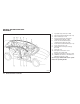
AIR BAGS, SEAT BELTS AND CHILD RESTRAINTS 1. 2. 3. 4. Top tether strap anchor (P. 1-38) Rear head restraints/headrests (P. 1-7) Rear seat belts (P. 1-15) Roof-mounted curtain side-impact supplemental air bag (P. 1-42) 5. Front seat-mounted side-impact supplemental air bags (P. 1-42) 6. Front head restraints/headrests (P. 1-7) 7. Front seat belts (P. 1-15) 8. Supplemental front-impact air bags (P. 1-42) 9. Seats (P. 1-2) 10. Occupant classification sensor (pattern sensor) (P.1-49) 11.
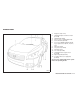
EXTERIOR FRONT 1. 2. 3. 4. 5. 6. 7. 8. 9. 10. 11. 12. 13. Engine hood (P. 3-17) Windshield wiper and washer switch (P. 2-28) Windshield (P. 8-20) Moonroof (if so equipped) (P. 2-46) Power windows (P. 2-43) Door locks, NISSAN Intelligent Key®, keys, request button (P. 3-4, 3-2, 3-2, 3-2) Mirrors (P. 3-25) Tire pressure (P. 8-32) Flat tire (P. 6-3) Tire chains (P. 8-40) Headlight and turn signal switch (P. 2-30) Replacing bulbs (P. 8-30) Fog light switch (if so equipped) (P.
EXTERIOR REAR 1. 2. 3. 4. 5. 6. 7. 8. 9. Rear window defroster switch (P. 2-29) Interior trunk lid release (P. 3-19) Trunk lid (P. 3-17) Vehicle loading (P. 9-12) Exterior trunk lid release/request button (P. 3-12) Replacing bulbs (P. 8-30) Fuel-filler cap, fuel recommendation (P. 3-20, P. 9-28 ) Fuel-filler door (P. 3-20) Child safety rear door locks (P. 3-6) See the page number indicated in parentheses for operating details.
PASSENGER COMPARTMENT 1. 2. 3. 4. 5. Interior trunk access (P. 1-5) Moonroof (if so equipped) (P. 2-46) Sun visors (P. 3-24) Interior lights, illuminated entry (P. 2-50) HomeLink® universal transceiver (if so equipped) (P. 2-53) 6. Interior mirrors (P. 3-25) 7. Glove box (P. 2-41) 8. Cup holders (P. 2-40) 9. Console box (P. 2-41) 10. Front seat (P. 1-2) 11. Rear seat (P. 1-5) See the page number indicated in parentheses for operating details.
INSTRUMENT PANEL 8. 9. 10. 11. 12. 13. 14. 15. 16. 17. 18. 19. WIC1535 1. 2. 3. Side and center vents (P. 4-28) Headlight/fog light (if so equipped)/turn signal switch (P. 2-30) Steering wheel switch for audio control and Bluetooth® Hands-Free Phone System (P. 4-89, 4-92) 0-6 Illustrated table of contents 4. 5. 6. 7. Meters and gauges (P. 2-3) Driver supplemental air bag/horn (P. 1-42, P. 2-34) Security indicator light (P. 2-26) Cruise control main/set switches (P. 5-19) 20. 21. 22. 23.
24. Vehicle Dynamic Control (VDC) OFF switch (P. 2-37) Outside mirror controls (P. 3-27) Heated steering wheel switch (if so equipped) (P. 2-37) Trunk lid release switch (P. 3-19) * Refer to the separate Navigation System Owner’s Manual (if so equipped). See the page number indicated in parentheses for operating details.
ENGINE COMPARTMENT CHECK LOCATIONS 1. 2. 3. 4. 5. 6. 7. 8. 9. 10. 11. 12. Power steering fluid reservoir (P. 8-13) Engine oil filler cap (P. 8-10) Brake fluid reservoir (P. 8-14) Air cleaner (P. 8-19) Fuse block (P. 8-22) Battery (P. 8-15) Fuse/fusible link box (P. 8-22) Engine oil dipstick (P. 8-10) Radiator cap (P. 8-8) Drive belt location (P.8-17) Engine coolant reservoir * (P. 8-8) Windshield-washer fluid reservoir * (P. 8-14) NOTE: * Side covers removed for clarity.
WARNING/INDICATOR LIGHTS Warning light or Name Page Anti-lock Braking System (ABS) warning light 2-11 Brake warning light 2-11 or Warning light Indicator light Name Page Name Page Seat belt warning light and chime 2-14 High beam indicator light (blue) 2-15 Supplemental air bag warning light 2-14 Malfunction Indicator Light (MIL) 2-15 Name Page Security indicator light 2-16 Continuously Variable Transmission (CVT) indicator light 2-14 Side light and headlight indicator light (gr
MEMO 0-10 Illustrated table of contents
1 Safety—Seats, seat belts and supplemental restraint system Seats . . . . . . . . . . . . . . . . . . . . . . . . . . . . . . . . . . . . . . . . . . . . 1-2 Front power seat adjustment. . . . . . . . . . . . . . . . . . . . . 1-3 Folding rear seat (if so equipped). . . . . . . . . . . . . . . . . 1-5 Front seat head restraints/headrests . . . . . . . . . . . . . . 1-7 Rear seat head restraints/headrests . . . . . . . . . . . . . 1-11 Seat belts . . . . . . . . . . . . . . . . . . . . . . . . . . . . . . .
SEATS ● Do not adjust the driver’s seat while driving so full attention may be given to vehicle operation. The seat may move suddenly and could cause loss of control of the vehicle. ● The seatback should not be reclined any more than needed for comfort. Seat belts are most effective when the passenger sits well back and straight up in the seat. If the seatback is reclined, the risk of sliding under the lap belt and being injured is increased.
The reclining feature allows adjustment of the seatback for occupants of different sizes for added comfort and to help obtain proper seat belt fit. See “Precautions on seat belt usage” later in this section. Also, the seatback can be reclined to allow occupants to rest when the vehicle is stopped and the shift lever is in P (Park).
LRS0862 LRS2191 Seat lifter (driver’s seat) Push the front or rear end of the switch up or down to adjust the angle and height of the seat cushion. Manual (if so equipped) Lumbar support (driver’s seat) The lumbar support feature provides adjustable lower back support to the driver. Move the lever up or down (manual) or move the switch forward or backward (power) to adjust the seat lumbar area.
Interior trunk access For models without a rear center console, the trunk can be accessed from the passenger side of the rear seat for loading and unloading, as shown. 1 䊊 2 䊊 Press down on the button on the rear parcel shelf. Fold down the passenger side seatback. WARNING ● Never allow anyone to ride in the cargo area or on the rear seat when it is in the fold-down position. Use of these areas by passengers without proper restraints could result in serious injury in an accident or sudden stop.
● When returning the seatbacks to the upright position, be certain they are completely secured in the latched position. If they are not completely secured, passengers may be injured in an accident or sudden stop. ● Closely supervise children when they are around cars to prevent them from playing and becoming locked in the trunk where they could be seriously injured. Keep the car locked, with the rear seatback and trunk lid securely latched when not in use, and prevent children’s access to car keys.
FRONT SEAT HEAD RESTRAINTS/ HEADRESTS WARNING WRS0868 Center armrest Pull the armrest down until it rests on the seat cushion. ● Head restraints/headrests supplement the other vehicle safety systems. They may provide additional protection against injury in certain rear end collisions. Adjust the head restraints/headrests properly, as specified in this section. Check the adjustment after someone else uses the seat.
● Adjustable head restraints/headrests have multiple notches along the stalk to lock them in a desired adjustment position. ● The non-adjustable head restraints/headrests have a single locking notch to secure them to the seat frame. ● Proper Adjustment: – For the adjustable type, align the head restraint/headrest so the center of your ear is approximately level with the center of the head restraint/headrest.
LRS2302 Removable Use the following procedure to remove the head restraints/headrests. 1. Pull the head restraint/headrest up to the highest position. 2. Push and hold the lock knob. LRS2303 Install 1. Align the head restraint/headrest stalks with the holes in the seat. Make sure the head restraint/headrest is facing the correct direction. The stalk with the notch (notches) 1 must be installed in the hole with the lock 䊊 2 . knob 䊊 3. Remove the head restraint/headrest from the seat. 2.
LRS2351 LRS2305 For non-adjustable head restraint/ headrest To raise the head restraint/headrest, pull it up. Make sure the head restraint/headrest is positioned so the lock knob is engaged in the notch before riding in that designated seating position. Make sure the head restraint/headrest is positioned so the lock knob is engaged in the notch before riding in that designated seating position.
● Your vehicle is equipped with a head restraint/headrest that may be integrated, adjustable or non-adjustable. REAR SEAT HEAD RESTRAINTS/ HEADRESTS ● Adjustable head restraints/headrests have multiple notches along the stalk to lock them in a desired adjustment position. WARNING ● Head restraints/headrests supplement the other vehicle safety systems. They may provide additional protection against injury in certain rear end collisions.
LRS2310 Adjustable head restraint/headrest components LRS2315 Non-adjustable head restraint/ headrest components LRS2074 Removal Use the following procedure to remove the head restraints/headrests. 1. Removable head restraint/headrest 1. Removable head restraint/headrest 2. Multiple notches 2. Single Notch 1. Adjust the seat or seatback as necessary. 3. Lock knobs 3. Lock knobs 2. Push and hold the lock knobs. 4. Stalks 4. Stalks 3.
LRS2075 Install 1. Align the head restraint/headrest stalks with the holes in the seat. Make sure the head restraint/headrest is facing the correct direction. 2. Push the head restraint/headrest down until it locks in place. WRS0134 For adjustable head restraint/headrest Adjust the head restraint/headrest so the center is level with the center of your ears. If your ear position is still higher than the recommended alignment, place the head restraint/headrest at the highest position.
LRS2305 To raise the head restraint/headrest, pull it up. Make sure the head restraint/headrest is positioned so the lock knob is engaged in the notch before riding in that designated seating position. LRS2306 To lower, push and hold the lock knob and push the head restraint/headrest down. Make sure the head restraint/headrest is positioned so the lock knob is engaged in the notch before riding in that designated seating position.
SEAT BELTS ● Do not attach anything to the head restraint/headrest stalks. Doing so could impair Active Head Restraint function. The Active Head Restraint moves forward utilizing the force that the seatback receives from the occupant in a rear-end collision. The movement of the head restraint/headrest helps support the occupant’s head by reducing its backward movement and helping absorb some of the forces that may lead to whiplash-type injuries.
SSS0134 WARNING ● Every person who drives or rides in this vehicle should use a seat belt at all times. Children should be properly restrained in the rear seat and, if appropriate, in a child restraint. 1-16 Safety—Seats, seat belts and supplemental restraint system SSS0016 WARNING ● The seat belt should be properly adjusted to a snug fit. Failure to do so may reduce the effectiveness of the entire restraint system and increase the chance or severity of injury in an accident.
● Be sure the seat belt tongue is securely fastened to the proper buckle. ● Do not wear the seat belt inside out or twisted. Doing so may reduce its effectiveness. ● Do not allow more than one person to use the same seat belt. ● Never carry more people in the vehicle than there are seat belts. SSS0014 WARNING ● Always route the shoulder belt over your shoulder and across your chest. Never put the belt behind your back, under your arm or across your neck.
PREGNANT WOMEN NISSAN recommends that pregnant women use seat belts. The seat belt should be worn snug and always position the lap belt as low as possible around the hips, not the waist. Place the shoulder belt over your shoulder and across your chest. Never run the lap/shoulder belt over your abdominal area. Contact your doctor for specific recommendations. INJURED PERSONS NISSAN recommends that injured persons use seat belts. Check with your doctor for specific recommendations.
LRS2190 Front seat shown Fastening the seat belts 1 䊊 Adjust the seat. See “Seats” earlier in this section. WRS0137 2 䊊 Slowly pull the seat belt out of the retractor and insert the tongue into the buckle until you hear and feel the latch engage. ● The retractor is designed to lock during a sudden stop or on impact. A slow pulling motion permits the seat belt to move, and allows you some freedom of movement in the seat.
The Emergency Locking Retractor (ELR) mode allows the seat belt to extend and retract to allow the driver and passengers some freedom of movement in the seat. The ELR locks the seat belt when the vehicle slows down rapidly or during certain impacts. The Automatic Locking Retractor (ALR) mode (child restraint mode) locks the seat belt for child restraint installation. WRS0138 3 䊊 䊊 4 Position the lap belt portion low and snug on the hips as shown.
To increase your confidence in the seat belts, check the operation as follows: WARNING ● After adjustment, release the adjustment button and try to move the shoulder belt anchor up and down to make sure it is securely fixed in position. ● Grasp the shoulder belt and pull forward quickly. The retractor should lock and restrict further belt movement. If the retractor does not lock during this check or if you have any questions about seat belt operation, see a NISSAN dealer.
CHILD SAFETY WARNING ● Only NISSAN seat belt extenders, made by the same company which made the original equipment seat belts, should be used with NISSAN seat belts. ● Adults and children who can use the standard seat belt should not use an extender. Such unnecessary use could result in serious personal injury in the event of an accident. ● If dirt builds up in the shoulder belt guide of the seat belt anchors, the seat belts may retract slowly. Wipe the shoulder belt guide with a clean, dry cloth.
There are three basic types of child restraint systems: ● Rear-facing child restraint ● Forward-facing child restraint ● Booster seat The proper restraint depends on the child’s size. Generally, infants up to about 1 year and less than 20 lbs (9 kg) should be placed in rear-facing child restraints. Forward-facing child restraints are available for children who outgrow rearfacing child restraints and are at least 1 year old.
CHILD RESTRAINTS Once a child outgrows the height or weight limit of the harness-equipped forward-facing child restraint, NISSAN recommends that the child be placed in a commercially available booster seat to obtain proper seat belt fit. For a seat belt to fit properly, the booster seat should raise the child so that the shoulder belt is properly positioned across the chest and the top, middle portion of the shoulder. The shoulder belt should not cross the neck or face and should not fall off the shoulder.
– Infants and children should never be held on anyone’s lap. Even the strongest adult cannot resist the forces of a collision. – Do not put a seat belt around both a child and another passenger. – NISSAN recommends that all child restraints be installed in the rear seat. Studies show that children are safer when properly restrained in the rear seat than in the front seat.
All U.S. states and Canadian provinces or territories require that infants and small children be restrained in an approved child restraint at all times while the vehicle is being operated. Canadian law requires the top tether strap on forward-facing child restraints be secured to the designated anchor point on the vehicle.
– Child restraint anchorages are designed to withstand only those loads imposed by correctly fitted child restraints. Under no circumstances are they to be used to attach adult seat belts or other items or equipment to the vehicle. Doing so could damage the child restraint anchorages. The child restraint will not be properly installed using the damaged anchorage, and a child could be seriously injured or killed in a collision.
REAR-FACING CHILD RESTRAINT INSTALLATION USING LATCH Refer to all Warnings and Cautions in the “Child safety” and “Child restraints” sections before installing a child restraint. Follow these steps to install a rear-facing child restraint using the LATCH system: 1. Position the child restraint on the seat. Always follow the child restraint manufacturer’s instructions.
WRS0801 Rear-facing web-mounted – step 2 2. Secure the child restraint anchor attachments to the LATCH lower anchors. Check to make sure the LATCH attachment is properly attached to the lower anchors. WRS0802 Rear-facing rigid-mounted – step 2 LRS0673 Rear-facing – step 3 3. For child restraints that are equipped with webbing-mounted attachments, remove any additional slack from the anchor attachments.
5. Check to make sure the child restraint is properly secured prior to each use. If the child restraint is loose, repeat steps 1 through 4. LRS0674 Rear-facing – step 4 4. After attaching the child restraint, test it before you place the child in it. Push it from side to side while holding the child restraint near the LATCH attachment path. The child restraint should not move more than 1 inch (25 mm), from side to side.
WARNING The three-point seat belt with Automatic Locking Retractor (ALR) must be used when installing a child restraint. Failure to use the ALR mode will result in the child restraint not being properly secured. The restraint could tip over or be loose and cause injury to a child in a sudden stop or collision. Also, it can change the operation of the front passenger air bag. See “Front passenger air bag and status light” later in this section.
LRS0669 Rear-facing – step 3 3. Pull the shoulder belt until the belt is fully extended. At this time, the seat belt retractor is in the Automatic Locking Retractor (ALR) mode (child restraint mode). It reverts to the Emergency Locking Retractor (ELR) mode when the seat belt is fully retracted. LRS0670 Rear-facing – step 4 4. Allow the seat belt to retract. Pull up on the shoulder belt to remove any slack in the belt.
7. Check to make sure that the child restraint is properly secured prior to each use. If the seat belt is not locked, repeat steps 1 through 6. After the child restraint is removed and the seat belt fully retracted, the ALR mode (child restraint mode) is canceled. FORWARD-FACING CHILD RESTRAINT INSTALLATION USING LATCH WRS0763 Rear-facing – step 6 6. After attaching the child restraint, test it before you place the child in it.
If the seating position does not have an adjustable head restraint/headrest and it is interfering with the proper child restraint fit, try another seating position or a different child restraint. WRS0800 Forward-facing rigid-mounted – step 2 3. The back of the child restraint should be secured against the vehicle seatback. If necessary, adjust or remove the head restraint/headrest to obtain the correct child restraint fit. If the head restraint/headrest is removed, store it in a secure place.
7. Check to make sure the child restraint is properly secured prior to each use. If the child restraint is loose, repeat steps 1 through 6. FORWARD-FACING CHILD RESTRAINT INSTALLATION USING THE SEAT BELTS WARNING WRS0697 Forward-facing – step 6 6. After attaching the child restraint, test it before you place the child in it. Push it from side to side while holding the child restraint near the LATCH attachment path. The child restraint should not move more than 1 inch (25 mm), from side to side.
2. Position the child restraint on the seat. Always follow the child restraint manufacturer’s instructions. The back of the child restraint should be secured against the vehicle seatback. If necessary, adjust or remove the head restraint/headrest to obtain the correct child restraint fit. If the head restraint/headrest is removed, store it in a secure place. Be sure to reinstall the head restraint/headrest when the child restraint is removed.
LRS0668 Forward-facing – step 5 5. Allow the seat belt to retract. Pull up on the shoulder belt to remove any slack in the belt. WRS0681 Forward-facing – step 6 6. Remove any additional slack from the seat belt; press downward and rearward firmly in the center of the child restraint with your knee to compress the vehicle seat cushion and seatback while pulling up on the seat belt. 7. Tighten the tether strap according to the manufacturer’s instructions to remove any slack.
9. Check to make sure the child restraint is properly secured prior to each use. If the seat belt is not locked, repeat steps 3 through 8. LRS0865 Forward-facing – step 10 10. If the child restraint is installed in the front passenger seat, place the ignition switch in the ON position. The front passenger air bag should illuminate. If this status light light is not illuminated, see ⬙Front passenger air bag and status light⬙ in this section. Move the child restraint to another seating position.
4. Refer to the appropriate child restraint installation procedure steps in this section before tightening the tether strap. If you have any questions when installing a top tether strap, consult your NISSAN dealer for details.
● Make sure the child’s head will be properly supported by the booster seat or vehicle seat. The seatback must be at or above the center of the child’s ears. For example, if a 1 is chosen, the low back booster seat 䊊 vehicle seatback must be at or above the center of the child’s ears. If the seatback is lower than the center of the child’s ears, a 2 should be used. high back booster seat 䊊 LRS0464 Booster seats of various sizes are offered by several manufacturers.
If the seating position does not have an adjustable head restraint/headrest and it is interfering with the proper booster seat fit, try another seating position or a different booster seat. 4. Position the lap portion of the seat belt low and snug on the child’s hips. Be sure to follow the booster seat manufacturer’s instructions for adjusting the seat belt routing. WRS0699 LRS0454 1. If you must install a booster seat in the front seat, move the seat to the rearmost position.
SUPPLEMENTAL RESTRAINT SYSTEM PRECAUTIONS ON SUPPLEMENTAL RESTRAINT SYSTEM This Supplemental Restraint System (SRS) section contains important information concerning the following systems: ● Driver and passenger supplemental frontimpact air bag (NISSAN Advanced Air Bag System) ● Front seat-mounted side-impact supplemental air bag LRS0865 7. If the booster seat is installed in the front passenger seat, place the ignition switch in the ON position.
● The driver and front passenger seat belt buckles are equipped with sensors that detect if the seat belts are fastened. The Advanced Air Bag System monitors the severity of a collision and seat belt usage then inflates the air bags as needed. Failure to properly wear seat belts can increase the risk or severity of injury in an accident. WRS0031 WARNING ● The front air bags ordinarily will not inflate in the event of a side impact, rear impact, rollover, or lower severity frontal collision.
ARS1133 ARS1041 WARNING ● Never let children ride unrestrained or extend their hands or face out of the window. Do not attempt to hold them in your lap or arms.
ARS1042 ARS1043 ARS1044 WARNING ● Children may be severely injured or killed when the front air bags, side air bags or curtain air bags inflate if they are not properly restrained. Pre-teens and children should be properly restrained in the rear seat, if possible.
ARS1045 WRS0256 SSS0101 ● Even with the NISSAN Advanced Air Bag System, never install a rear-facing child restraint in the front seat. An inflating front air bag could seriously injure or kill your child. See “Child restraints” earlier in this section for details.
WARNING SSS0188 ● The seat belts, the side air bags and curtain air bags are most effective when you are sitting well back and upright in the seat with both feet on the floor. The side air bag and curtain air bag inflate with great force. Do not allow anyone to place their hand, leg or face near the side air bag on the side of the seatback of the front seat or near the side roof rails.
SSS0159 1-48 Safety—Seats, seat belts and supplemental restraint system SSS0162
8. Seat belt buckle switches for driver’s and passenger’s side 9. Occupant classification sensor (pattern sensor) 10. Seat belt with pretensioner 11. Side satellite sensor NISSAN Advanced Air Bag System (front seats) This vehicle is equipped with the NISSAN Advanced Air Bag System for the driver and front passenger seats. This system is designed to meet certification requirements under U.S. regulations. It is also permitted in Canada.
The NISSAN Advanced Air Bag System has dual stage inflators. It also monitors information from the crash zone sensor, the Air Bag Control Unit (ACU), seat belt buckle sensors and the occupant classification sensor (pattern sensor). Inflator operation is based on the severity of a collision and seat belt usage for the driver. For the front passenger, the occupant classification sensor is also monitored.
Status light is The front passenger air bag status light located above the radio. After the ignition switch is placed in the ⬙ON⬙ position, the front passenger air bag status light on the instrument panel illuminates for about 7 seconds and then turns off or remains illuminated depending on the front passenger seat occupied status. The light operates as follows: is ● Unoccupied passenger’s seat: The OFF and the front passenger air bag is OFF and will not inflate in a crash.
Front passenger seat adult occupants who are properly seated and using the seat belt as outlined in this manual should not cause the passenger air bag to be automatically turned OFF. For small adults it may be turned OFF, however if the occupant takes his/her weight off the seat cushion (for example, by not sitting upright, by sitting on an edge of the seat, or by otherwise being out of position), this could cause the sensor to turn the air bag OFF.
Other supplemental front-impact air bag precautions WARNING ● Do not place any objects on the steering wheel pad or on the instrument panel. Also, do not place any objects between any occupant and the steering wheel or instrument panel. Such objects may become dangerous projectiles and cause injury if the front air bags inflate. ● Immediately after inflation, several front air bag system components will be hot. Do not touch them; you may severely burn yourself.
are designed to inflate on the side where the vehicle is impacted. They may not inflate in certain side collisions. Vehicle damage (or lack of it) is not always an indication of proper side air bag and curtain air bag operation. When the side air bags and curtain air bags inflate, a fairly loud noise may be heard, followed by release of smoke. This smoke is not harmful and does not indicate a fire. Care should be taken not to inhale it, as it may cause irritation and choking.
● No unauthorized changes should be made to any components or wiring of the side air bag and curtain air bag systems. This is to prevent damage to or accidental inflation of the side air bag and curtain air bag or damage to the side air bag and curtain air bag systems. * The SRS wiring harness connectors are yellow and orange for easy identification. ● Do not make unauthorized changes to your vehicle’s electrical system, suspension system or side panel.
After pretensioner activation, load limiters allow the seat belt to release webbing (if necessary) to reduce forces against the chest. is The supplemental air bag warning light used to indicate malfunctions in the pretensioner system. (See ⬙SUPPLEMENTAL AIR BAG WARNING LIGHT⬙ in this section for more details.) If the operation of the supplemental air bag warning light indicates there is a malfunction, have the system checked by a NISSAN dealer.
If any of the following conditions occur, the front air bag, side air bag, curtain air bag and pretensioner systems need servicing: ● The supplemental air bag warning light remains on after approximately 7 seconds. ● The supplemental air bag warning light flashes intermittently. ● The supplemental air bag warning light does not come on at all. Under these conditions, the front air bag, side air bag, curtain air bag or pretensioner systems may not operate properly. They must be checked and repaired.
2 Instruments and controls Instrument panel. . . . . . . . . . . . . . . . . . . . . . . . . . . . . . . . . . . 2-2 Meters and gauges . . . . . . . . . . . . . . . . . . . . . . . . . . . . . . . . 2-3 Speedometer and odometer . . . . . . . . . . . . . . . . . . . . . 2-4 Tachometer . . . . . . . . . . . . . . . . . . . . . . . . . . . . . . . . . . . . 2-5 Engine coolant temperature gauge . . . . . . . . . . . . . . . 2-5 Fuel gauge . . . . . . . . . . . . . . . . . . . . . . . . . . . . . . . . . . . .
Moonroof (if so equipped) . . . . . . . . . . . . . . . . . . . . . . . . . 2-46 Power moonroof. . . . . . . . . . . . . . . . . . . . . . . . . . . . . . . 2-46 Dual Panel Moonroof (if so equipped). . . . . . . . . . . . . . . 2-47 Power moonroof. . . . . . . . . . . . . . . . . . . . . . . . . . . . . . . 2-47 Rear power sun shade (if so equipped) . . . . . . . . . . . . . 2-49 Interior light . . . . . . . . . . . . . . . . . . . . . . . . . . . . . . . . . . . . . . 2-50 Console light. . . . . . . . . .
INSTRUMENT PANEL 8. 9. 10. 11. 12. 13. 14. 15. 16. 17. 18. 19. WIC1535 1. 2. 3. Side and center vents (P. 4-28) Headlight/fog light (if so equipped)/turn signal switch (P. 2-30) Steering wheel switch for audio control and Bluetooth® Hands-Free Phone System (P. 4-89, 4-92) 2-2 Instruments and controls 4. 5. 6. 7. Meters and gauges (P. 2-3) Driver supplemental air bag/horn (P. 1-42, P. 2-34) Security indicator light (P. 2-26) Cruise control main/set switches (P. 5-19) 20. 21. 22. 23.
METERS AND GAUGES 24. Vehicle Dynamic Control (VDC) OFF switch (P. 2-37) Outside mirror controls (P. 3-27) Heated steering wheel switch (if so equipped) (P. 2-37) Trunk lid release switch (P. 3-19) * Refer to the separate Navigation System Owner’s Manual (if so equipped). See the page number indicated in parentheses for operating details. LIC1381 1. 2. 3. 4. 5. 6. Tachometer Speedometer Warning/indicator lights Fuel gauge Odometer/twin trip odometer Trip odometer change button 7. 8.
Changing the display: 3 to change the disPress the change button 䊊 play as follows: Trip → Trip → Trip Resetting the trip odometer: 3 for more than 1 secPress the change button 䊊 ond to reset the currently displayed trip odometer to zero. LIC1382 LIC1383 SPEEDOMETER AND ODOMETER Odometer/Twin trip odometer Speedometer The odometer/twin trip odometer is displayed when the ignition switch is placed in the ON position. The speedometer indicates the vehicle speed.
CAUTION If the gauge indicates coolant temperature near the hot (H) end of the normal range, reduce vehicle speed to decrease temperature. If the gauge is over the normal range, stop the vehicle as soon as safely possible. If the engine is overheated, continued operation of the vehicle may seriously damage the engine. See “If your vehicle overheats” in the “In case of emergency” section for immediate action required. LIC1384 TACHOMETER The tachometer indicates engine speed in revolutions per minute (RPM).
COMPASS DISPLAY (if so equipped) Refill the fuel tank before the gauge registers E (Empty). This unit measures terrestrial magnetism and indicates the heading direction of the vehicle. indicates that the fuel-filler door is The located on the driver’s side of the vehicle. With the ignition placed in the ON position, press button as described in the charts bethe low to activate various features of the automatic anti-glare rearview mirror.
You can also calibrate the compass by driving your vehicle on your everyday route. The compass will be calibrated once it has tracked three complete circles. LIC1487 COMPASS DISPLAY Push the button for about 1 second when the ignition switch is placed in the ON position to toggle the outside temperature and compass 1 on or off. The display will direction display 䊊 indicate the direction that the vehicle is heading.
Zone variation change procedure The difference between magnetic north and geographical north is known as variance. In some areas, this difference can sometimes be great enough to cause false compass readings. Follow these instructions to set the variance for your particular location if this happens: button for about 1. Press and hold the 8 seconds. The current zone number will appear in the display. Release the button. 2. Find your current location on the zone map. Refer to the illustration.
1. With the display turned on, press and hold the for about 10 seconds. The “C” icon in the compass display will illuminate. 2. Calibrate the compass by driving the vehicle in three complete circles at a maximum speed of 5 MPH (8 km/h). 3. After completing the circles, the display should return to normal. CAUTION ● Do not install a ski rack, antenna, etc., which are attached to the vehicle by means of a magnet. They affect the operation of the compass.
WARNING/INDICATOR LIGHTS AND AUDIBLE REMINDERS or Anti-lock Braking System (ABS) warning light Supplemental air bag warning light Malfunction Indicator Light (MIL) or Brake warning light Continuously Variable Transmission (CVT) indicator light Security indicator light Charge warning light Continuously Variable Transmission (CVT) position indicator light Side light and headlight indicator light (green) Engine oil pressure warning light Cruise main switch indicator light Slip indicator light Lo
or Anti-lock Braking System (ABS) warning light When the ignition switch is placed in the ON position, the Anti-lock Braking System (ABS) warning light illuminates and then turns off. This indicates the ABS is operational. If the ABS warning light illuminates while the engine is running or while driving, it may indicate the ABS is not functioning properly. Have the system checked by a NISSAN dealer. If an ABS malfunction occurs, the anti-lock function is turned off.
CAUTION ● Do not ground electrical accessories directly to the battery terminal. Doing so will bypass the variable control system and the vehicle battery may not charge completely. Refer to “Variable voltage control system (if so equipped) ” in the “Maintenance and do-it-yourself” section later in this manual. ● Do not continue driving if the generator belt is loose, broken or missing. Engine oil pressure warning light This light warns of low engine oil pressure.
TPMS malfunction: If the TPMS is not functioning properly, the low tire pressure warning light will flash for approximately 1 minute when the ignition switch is placed in the ON position. The light will remain on after the 1 minute. Have the system checked by a NISSAN dealer. The CHECK TIRE PRESSURE warning does not appear if the low tire pressure warning light illuminates to indicate a TPMS malfunction.
Master warning light When the ignition is in the ON position, the master warning light illuminates if any of the following are displayed on the vehicle information display. ● No key warning ● Low fuel warning ● Low windshield-washer fluid warning ● Parking brake release warning ● Door/trunk open warning ● Loose fuel cap ● Check tire pressure warning Seat belt warning light and chime The light and chime remind you to fasten your seat belts.
Continuously Variable Transmission (CVT) position indicator light When the ignition switch is placed in the ON position, the indicator light shows the shift lever position. See “Driving the vehicle” in the “Starting and driving” section of this manual. Cruise main switch indicator light The light comes on when the cruise control main switch is pushed. The light goes out when the main switch is pushed again. When the cruise main switch indicator light comes on, the cruise control system is operational.
● Malfunction indicator light blinking — An engine misfire has been detected which may damage the emission control system. To reduce or avoid emission control system damage: – do not drive at speeds above 45 MPH (72 km/h). – avoid hard acceleration or deceleration. – avoid steep uphill grades. – if possible, reduce the amount of cargo being hauled or towed. The malfunction indicator light may stop blinking and come on steady. Have the vehicle inspected by a NISSAN dealer.
VEHICLE INFORMATION DISPLAY AUDIBLE REMINDERS Brake pad wear warning The disc brake pads have audible wear warnings. When a disc brake pad requires replacement, it makes a high pitched scraping sound when the vehicle is in motion, whether or not the brake pedal is depressed. Have the brakes checked as soon as possible if the warning sound is heard. NISSAN Intelligent Key® door buzzer The Intelligent Key door buzzer sounds if the Intelligent Key is left inside the vehicle when locking the doors.
WIC1406 HOW TO USE THE VEHICLE INFORMATION DISPLAY Press the button, located on the instrument panel just behind the steering wheel, to display the following modes: MPG → MPG/MPH → Time/Miles → Range → Tire Pressure → Exterior Temperature → Setting → Warning 2-18 Instruments and controls LIC2171 LIC2172 Fuel economy mode Average speed mode The fuel economy mode can be selected to display the instant fuel economy since the last reset.
LIC2173 LIC2174 LIC2175 Time/Miles (km) mode Range mode Tire pressure mode The time/miles (km) mode can be selected to show the time and distance driven since the last reset. The range mode can be selected to give you an estimation of the distance that can be driven before refueling. The range is constantly calculated based on the amount of fuel in the fuel tank and the actual fuel consumption.
In case of a low tire pressure, a warning message will also appear in the vehicle information display. See “Check tire pressure warning” later in this section. LIC2176 LIC1541 Exterior temperature mode Setting mode The exterior temperature mode can be selected to provide you with the temperature outside of your vehicle. The setting mode allows you to set reminders or preferences for alerts, maintenance intervals or language displays.
LIC1044 LIC2587 LIC2177 Alert mode Reset mode Maintenance mode The alert mode allows you to set alerts notifying you of time to rest or icy conditions. The reset mode can be selected in any screen that allows for preferences to be programmed. Once the screen is selected, you have the option to reset the selected distances or time to a new setting.
You can select the language, unit or change the button and dial effects by using the pressing . The settings are automatically saved when you exit the menu by pressing the BACK button or any other mode button. LIC2178 LIC1098 Options mode Warning mode The LANGUAGE/UNIT/EFFECTS screen will appear when selecting the “Language/Unit/Effects” key and . pressing The warning mode can be selected to view any warnings that may be present.
LIC2576 Vehicle information display warnings and indicators 4. Low windshield-washer fluid warning 5. No key warning 8. Engine start operation indicator 9. NISSAN Intelligent Key® insertion indicator 1. Door and trunk open warning 6. Parking brake warning 10. NISSAN Intelligent Key® removal indicator 2. Push warning 7. Shift P warning 11. NISSAN Intelligent Key® battery discharge indicator 3.
12. Loose fuel cap warning Low windshield-washer fluid warning 13. Check tire pressure warning This warning illuminates when the windshieldwasher fluid is at a low level. Add windshieldwasher fluid as necessary. See “Windshieldwasher fluid” in the “Maintenance and do-ityourself” section of this manual. 14. Tire pressure warning 15. I-Key System Error: See Owner’s Manual Door and trunk open warning This warning illuminates when a door or the trunk has been opened when the engine is running.
This indicator means that the engine will start by pushing the push-button ignition switch with the brake pedal depressed. If this indicator illuminates, replace the battery with a new one. See “Battery replacement” in the “Maintenance and do-it-yourself” section. update the numbers. Refer to “Tire Pressure Monitoring System” in the “Starting and driving” section.
SECURITY SYSTEMS ways secure your vehicle even if parking for a brief period. Never leave your Intelligent Key in the vehicle, and always lock the vehicle when unattended. Be aware of your surroundings, and park in secure, well-lit areas whenever possible. Many devices offering additional protection, such as component locks, identification markers, and tracking systems, are available at auto supply stores and specialty shops. Your NISSAN dealer may also offer such equipment.
The alarm is activated by: ● opening the door or trunk lid without using the key or Intelligent Key (even if the door is unlocked by releasing the door inside lock switch). How to stop an activated alarm The alarm stops only by unlocking the driver’s door or the trunk lid with the key, pressing button on the Intelligent Key, or pressthe ing the request switch on the driver’s or passenger’s door with the Intelligent Key in range of the door handle.
WINDSHIELD WIPER AND WASHER SWITCH NOTE: You can turn on or turn off the driving speed dependent intermittent wiper function for vehicles with navigation system. Refer to “Comfort settings” in the “Monitor, climate, audio, phone and voice recognition systems” section. 2 䊊 3 䊊 Low — continuous low speed operation High — continuous high speed operation 4 to have one sweep operaPush the lever up 䊊 tion of the wiper.
REAR WINDOW AND OUTSIDE MIRROR (if so equipped) DEFROSTER SWITCH CAUTION ● Do not operate the washer continuously for more than 30 seconds. ● Do not operate the washer if the windshield-washer fluid reservoir is empty. ● Do not fill the windshield-washer fluid reservoir with washer fluid concentrates at full strength. Some methyl alcohol based washer fluid concentrates may permanently stain the grille if spilled while filling the windshieldwasher fluid reservoir.
HEADLIGHT AND TURN SIGNAL SWITCH XENON HEADLIGHTS (if so equipped) WARNING cHIGH VOLTAGE ● When xenon headlights are on, they produce a high voltage. To prevent an electric shock, never attempt to modify or disassemble. Always have your xenon headlights replaced at a NISSAN dealer. ● Xenon headlights provide considerably more light than conventional headlights. If they are not correctly aimed, they might temporarily blind an oncoming driver or the driver ahead of you and cause a serious accident.
CAUTION Use the headlights with the engine running to avoid discharging the vehicle battery. WIC1436 Type B HEADLIGHT CONTROL SWITCH Lighting 1 䊊 2 䊊 LIC1086 Autolight system The autolight system allows the headlights to be set so they turn on and off automatically. The autolight system can: When turning the switch to the position, the front parking, tail, license plate and instrument panel lights come on.
To turn on the autolight system: 1. Place the headlight switch in the AUTO po1 . sition 䊊 2. Place ignition in the ON position. 3. The autolight system automatically turns the headlights on and off. Initially, if the ignition switch is placed in the OFF position and a door is opened and left open, the headlights remain ON for a period of time. If another door is opened while the headlights are on, then the timer is reset. To turn the autolight system off, turn the switch to , or position.
CAUTION Even though the battery saver feature automatically turns off the headlights after a period of time, you should turn the headlight switch to the OFF position when the engine is not running to avoid discharging the vehicle battery. WARNING When the daytime running light system is active, tail lights on your vehicle are not on. It is necessary at dusk to turn on your headlights. Failure to do so could cause an accident injuring yourself and others.
HORN WIC1440 LIC1389 TURN SIGNAL SWITCH WIC1439 FOG LIGHT SWITCH (if so equipped) Turn signal To sound the horn, push near the horn icon on the steering wheel. To turn the fog lights on, turn the headlight switch position, then turn the fog light to the switch to the position. 1 䊊 Move the lever up or down to signal the turning direction. When the turn is completed, the turn signal cancels automatically.
HEATED SEATS (if so equipped) WARNING Do not use or allow occupants to use the seat heater if you or the occupants cannot monitor elevated seat temperatures or have an inability to feel pain in body parts that contact the seat. Use of the seat heater by such people could result in serious injury. ● If any malfunctions are found or the heated seat does not operate, turn the switch off and have the system checked by your NISSAN dealer.
CLIMATE CONTROL SEAT SWITCH (if so equipped) mately 60 seconds after turning the switch on or selecting the desired temperature. 4. When the vehicle’s interior is warmed or cooled, or before you leave the vehicle, be sure to turn the control knob to the Off (center) position To check the air filter for the climate controlled seat, contact a NISSAN dealer. WARNING LIC1410 The climate controlled seat warms up or cools down the front seat by blowing warm or cool air from the surface of the seat.
HEATED STEERING WHEEL (if so equipped) VEHICLE DYNAMIC CONTROL (VDC) OFF SWITCH NOTE: If the surface temperature of the steering wheel is above 68°F (20°C) when the switch is turned on, the system will not heat the steering wheel. This is not a malfunction. LIC0421 LIC1548 The heated steering wheel system is designed to operate only when the surface temperature of the steering wheel is below 68°F (20°C).
POWER OUTLET STORAGE CAUTION LIC1392 Front center console The power outlets are for powering electrical accessories such as cellular telephones. They are rated at 12 Volt, 120 W (10A) maximum. The power outlets are powered only when the ignition switch is in the ACC or ON position. 2-38 Instruments and controls ● The outlet and plug may be hot during or immediately after use. ● Only certain power outlets are designed for use with a cigarette lighter unit.
CAUTION ● Do not use for anything other than sunglasses. ● Do not leave sunglasses in the sunglasses holder while parking in direct sunlight. The heat may damage the sunglasses. LIC0016 WIC1551 SEATBACK POCKETS SUNGLASSES HOLDER The seatback pockets are located on the back of the driver’s and passenger’s seats. The pockets can be used to store maps. To open the sunglasses holder, push and release. Only store one pair of sunglasses in the holder.
The rear cup holders are located in the fold-down armrest in the rear seat back. LIC1395 Front CUP HOLDERS CAUTION ● Avoid abrupt starting and braking when the cup holder is being used to prevent spilling the drink. If the liquid is hot, it can scald you or your passenger. ● Use only soft cups in the cup holder. Hard objects can injure you in an accident. To open the front cup holders, push the cup holder lid. To close, lower the cup holder lid and push down until it clicks in place.
WIC1216 Soft bottle holder Soft bottle holder CAUTION ● Do not use bottle holder for any other objects that could be thrown about in the vehicle and possibly injure people during sudden braking or an accident. ● Do not use bottle holder for open liquid containers. LIC1396 WIC1120 GLOVE BOX CONSOLE BOX Open the glove box by pulling the handle. Use the 1 or unlocking 䊊 2 mechanical key when locking 䊊 the glove box.
WIC1121 LIC0748 Lower half GROCERY HOOKS Pull up on the passenger’s side latch to open the lower half of the console box. A power outlet is located inside the console box and there is storage for compact discs. The grocery hooks are located in the trunk and can be used to hang a standard size plastic grocery bag. CAUTION Do not apply a total load of more than 20 lbs (9 kg) to a single grocery hook.
WINDOWS POWER WINDOWS WARNING ● Make sure that all passengers have their hands, etc. inside the vehicle while it is in motion and before closing the windows. Use the window lock switch to prevent unexpected use of the power windows. LIC0802 To install a cargo net, attach the net to the retainers. To remove a cargo net, detach the net from the retainers. ● Do not leave children unattended inside the vehicle. They could unknowingly activate switches or controls and become trapped in a window.
Driver’s side power window switch The driver’s side control panel is equipped with switches to open or close all of the windows. To open a window, push the switch to the first detent and continue to hold down until the desired window position is reached. To close a window, pull the switch to the first detent and continue to hold up until the desired window position is reached. WIC1265 Front passenger’s power window switch The passenger’s window switch operates only the corresponding passenger’s window.
Auto-reverse function The auto-reverse function can be activated when a window is closed by automatic operation. Depending on the environment or driving conditions, the auto-reverse function may be activated if an impact or load similar to something being caught in the window occurs. WARNING LIC0410 Automatic operation To fully open a window equipped with automatic operation, press the window switch down to the second detent and release it; it need not be held. The window automatically opens all the way.
MOONROOF (if so equipped) To open or close the moonroof part way, push the switch in any direction while the moonroof is sliding to stop it in the desired position. Tilting the moonroof Close the moonroof by pushing the switch 2 . Release the switch, then push toward 䊊 2 again to tilt the the switch toward 䊊 moonroof up. To tilt the moonroof down, push the switch 1 . toward 䊊 WARNING LIC1408 POWER MOONROOF The moonroof will only operate when the ignition switch is placed in the ON position.
DUAL PANEL MOONROOF (if so equipped) When closing: CAUTION If the control unit detects something caught in the moonroof as it moves to the front, the moonroof will immediately open backward. When tilting down: If the control unit detects something caught in the moonroof as it tilts down, the moonroof will immediately tilt up.
Sliding the moonroof To slide the moonroof: ● To fully open the moonroof, push the switch 1 toward the open position until it reaches 䊊 1 is the second detent. If the switch 䊊 pushed to the first detent, only the sunshade will open. ● To fully close the moonroof, push the switch 2 toward the close position until it reaches 䊊 2 is the second detent. If the switch 䊊 pushed to the first detent, the moonroof will close but the sunshade will remain open.
REAR POWER SUN SHADE (if so equipped) To close the sunshade: ● To fully close the sunshade, push the switch 2 toward the close position until it reaches 䊊 the second detent. 2 to the first detent will ● Pushing the switch 䊊 close the moonroof only. If the moonroof does not close Have your NISSAN dealer check and repair the moonroof. WIC1445 Sunshade To open the sunshade: ● To fully open the sunshade, push the switch 1 toward the open position until it reaches 䊊 the first detent.
INTERIOR LIGHT – Driver’s door is opened. Lights remain on for a period of time after driver’s door is closed. CAUTION ● Do not place objects (such as newspapers, handkerchiefs, etc.) on the screen inlet port. Doing so may entangle these objects in the screen when it is extending or retracting, causing improper operation or damage to the screen. – Ignition switch is placed in the OFF position. The lights will go off when the ignition switch is in the ON position, or the driver’s door is closed and locked.
PERSONAL LIGHTS NOTE: The footwell and doorstep lights illuminate when the driver and passenger doors are opened regardless of the interior light switch position. These lights will turn off automatically after a period of time while doors are open to prevent the battery from becoming discharged. CAUTION Do not use for extended periods of time with the engine stopped. This could result in a discharged battery.
WIC1494 Models without moonroof 2-52 Instruments and controls WIC1494 Models with moonroof LIC1409 Models with dual panel moonroof
MAP LIGHTS TRUNK LIGHT HOMELINK® UNIVERSAL TRANSCEIVER (if so equipped) To turn the map lights on, press the switches. To turn them off, press the switches again. The light illuminates when the trunk lid is opened. When the trunk lid is closed, the light goes off. The HomeLink® Universal Transceiver provides a convenient way to consolidate the functions of up to three individual hand-held transmitters into one built-in device. CAUTION Do not use for extended periods of time with the engine stopped.
WARNING ● Do not use the HomeLink® Universal Transceiver with any garage door opener that lacks safety stop and reverse features as required by federal safety standards. (These standards became effective for opener models manufactured after April 1, 1982). A garage door opener which cannot detect an object in the path of a closing garage door and then automatically stop and reverse, does not meet current federal safety standards.
Do not stand on your vehicle to perform the next steps. 4. At the receiver located on the garage door opener motor in the garage, locate the “learn” or “smart” button (the name and color of the button may vary by manufacturer but it is usually located near where the hanging antenna wire is attached to the unit). If there is difficulty locating the button, reference the garage door opener’s manual. 5. Press and release the “learn” or “smart” button. LIC2366 3.
press and hold the desired HomeLink® button while you press and re-press (“cycle”) your hand-held transmitter every two seconds until the frequency signal has been learned. The HomeLink® indicator light will flash slowly and then rapidly after several seconds upon successful training. DO NOT release until the HomeLink® indicator light flashes slowly and then rapidly. When the indicator light flashes rapidly, both buttons may be released. The rapid flashing indicates successful training.
2. The indicator light will begin to flash after 20 seconds. Without releasing the HomeLink® button, proceed with “Programming HomeLink®” - Step 1. For questions or comments, contact HomeLink® at: www.homelink.com or 1–800–355–3515 (except Mexico). The HomeLink® Universal Transceiver button has now been reprogrammed. The new device can be activated by pushing the HomeLink® button that was just programmed. This procedure will not affect any other programmed HomeLink® buttons.
MEMO 2-58 Instruments and controls
3 Pre-driving checks and adjustments Keys . . . . . . . . . . . . . . . . . . . . . . . . . . . . . . . . . . . . . . . . . . . . . 3-2 NISSAN Intelligent Key® . . . . . . . . . . . . . . . . . . . . . . . . 3-2 NISSAN Vehicle Immobilizer System keys . . . . . . . . . 3-3 Doors . . . . . . . . . . . . . . . . . . . . . . . . . . . . . . . . . . . . . . . . . . . . 3-4 Locking with key. . . . . . . . . . . . . . . . . . . . . . . . . . . . . . . . 3-4 Locking with inside lock knob . . . . . . . . . . . . .
KEYS Never leave these keys in the vehicle. As many as 4 Intelligent Keys can be registered and used with one vehicle. The new keys must be registered by a NISSAN dealer prior to use with the Intelligent Key system and NISSAN Vehicle Immobilizer System of your vehicle. Since the registration process requires erasing all memory in the Intelligent Key components when registering new keys, be sure to take all Intelligent Keys that you have to the NISSAN dealer. WPD0427 1. 2. 3.
CAUTION Always carry the mechanical key installed in the Intelligent Key slot. See “Doors” in this section and “Storage” in the “Instruments and controls” section of this manual. Valet hand-off When you have to leave a key with a valet, give them the Intelligent Key itself and keep the mechanical key with you to protect your belongings. SPA1951 Mechanical key The Intelligent Key contains the mechanical key, which can be used in case of a discharged battery.
DOORS Any key that is not given to your dealer at the time of registration will no longer be able to start your vehicle. When the doors are locked using one of the following methods, the doors can not be opened using the inside or outside door handles. The doors must be unlocked to open the doors. CAUTION Do not allow the immobilizer system key, which contains an electrical transponder, to come into contact with water or salt water. This could affect system function.
Opening and closing windows The driver’s door key operation allows you to open and close windows equipped with automatic operation at the same time. ● To open the windows, turn the driver’s door key toward the rear of the vehicle for longer than 1 second after the door is unlocked. ● To close the windows, turn the driver’s door key toward the front of the vehicle for longer than 1 second after the door is locked. Windows stop when the key cylinder is released.
Lockout protection When the power door lock switch (driver’s or front passenger’s side) is moved to the lock position with the Intelligent Key in the port and any door open, all doors will lock and unlock automatically. With the Intelligent Key left in the vehicle (not in the Intelligent Key port) and any door open, all doors will unlock automatically and a chime will sound after the door is closed. AUTOMATIC DOOR LOCKS ● All doors lock automatically when the vehicle speed reaches 15 MPH (24 km/h).
NISSAN INTELLIGENT KEY® WARNING ● Radio waves could adversely affect electric medical equipment. Those who use a pacemaker should contact the electric medical equipment manufacturer for the possible influences before use. ● The Intelligent Key transmits radio waves when the buttons are pressed. The FAA advises the radio waves may affect aircraft navigation and communication systems. Do not operate the Intelligent Key while on an airplane.
CAUTION Listed below are conditions or occurrences which will damage the Intelligent Key: ● Do not allow the Intelligent Key, which contains electrical components, to come into contact with water or salt water. This could affect the system function. If an Intelligent Key is lost or stolen, NISSAN recommends erasing the ID code of that Intelligent Key from the vehicle. This may prevent the unauthorized use of the Intelligent Key to operate the vehicle.
● To prevent the Intelligent Key from being left inside the vehicle, make sure you carry the Intelligent Key with you and then lock the doors. If the Intelligent Key is too close to the door glass, handle or rear bumper, the request switches may not function. When the Intelligent Key is within the operating range, it is possible for anyone, even someone who does not carry the Intelligent Key, to push the request switch to lock/unlock the doors.
WPD0376 NISSAN INTELLIGENT KEY® OPERATION You can lock or unlock the doors without taking the Intelligent Key out of your pocket or bag. When you carry the Intelligent Key with you, you can lock or unlock all doors by pushing the door handle request switch within the range of operation. WPD0377 Locking doors 1. Move the shift lever to the P (Park) position. Place the ignition switch in the LOCK position. Make sure the Intelligent Key is not left in the vehicle. 2. Close all doors. 1 3.
● Doors do not lock with the door handle request switch with the Intelligent Key inside the vehicle and a beep sounds to warn you. However, when an Intelligent Key is inside the vehicle, doors can be locked with another Intelligent Key. CAUTION ● After locking the doors using the request switch, make sure that the doors have been securely locked by operating the door handles or the trunk opener switch.
The interior light can be turned off without waiting by performing one of the following operations. ● Placing the ignition switch in the ON position. ● Locking the doors with the remote controller. ● Switching the room light switch to the OFF position. WPD0369 All doors will be locked automatically unless one of the following operations is performed within 60 seconds after pushing the request switch. ● Opening any door. ● Pushing the ignition switch.
When all doors are locked and the trunk lid is closed with the Intelligent Key inside the trunk, the outside buzzer will sound and the trunk will open. CAUTION After locking the doors using the Intelligent Key, be sure that the doors have been securely locked by operating the door handles. HOW TO USE THE REMOTE KEYLESS ENTRY FUNCTION The remote keyless entry function can operate all door locks using the remote keyless function of the Intelligent Key.
The interior light illuminates for a period of time when a door is unlocked and the room light switch is in the DOOR position. The light can be turned off without waiting by performing one of the following operations. ● Placing the ignition switch in the ON position. ● Locking the doors with the remote controller. ● Switching the room light switch to the OFF position. Opening windows WPD0360 Unlocking doors 1. Press the Key. button on the Intelligent 2. The hazard warning lights flash once.
The hazard warning lights will flash once and the horn will sound once to confirm that the horn beep feature has been reactivated. Deactivating the horn beep feature does not silence the horn if the alarm is triggered. WARNING SIGNALS To help prevent the vehicle from moving unexpectedly by erroneous operation of the Intelligent Key or to help prevent the vehicle from being stolen, a chime or buzzer sounds from inside and outside the vehicle and a warning is displayed in the instrument panel.
TROUBLESHOOTING GUIDE Verify the location of all Intelligent Keys that are programmed for the vehicle. If another Intelligent Key is in range or inside the vehicle, the vehicle system may respond differently than expected. Symptom The SHIFT P warning appears on the display and the inside warning chime sounds continuously.
HOOD TRUNK LID WARNING ● Do not drive with the trunk lid open. This could allow dangerous exhaust gases to be drawn into the vehicle. See “Exhaust gas” in the “Starting and driving” section of this manual. LRS2008 1 䊊 2 䊊 Pull the hood lock release handle located below the driver side instrument panel. The hood will spring up slightly. Push the lever at the front of the hood to the side as illustrated with your fingertips and raise the hood.
● Closely supervise children when they are around cars to prevent them from playing and becoming locked in the trunk where they could be seriously injured. Keep the car locked, with the rear seatback and trunk lid securely latched when not in use, and prevent children’s access to car keys. To open the trunk lid, push the opener switch down. To close the trunk lid, lower and push the trunk lid down securely. LPD0394 OPENER OPERATION WARNING ● Do not drive with the trunk lid open.
To open the trunk from the inside, pull the illuminated release handle until the lock releases and push up on the trunk lid. The release handle is made of a material that glows in the dark after a brief exposure to ambient light. The handle is located inside the trunk compartment on the interior of the trunk lid.
FUEL-FILLER DOOR To lock, close the fuel-filler door securely and lock the doors. NOTE: The fuel-filler door will unlock using the key only when all doors are unlocked. Unlocking the driver’s door will not unlock the fuel-filler door. FUEL-FILLER CAP WARNING WPD0454 OPENING THE FUEL-FILLER DOOR The fuel-filler door automatically unlocks when the driver’s door is unlocked. 1. Unlock the fuel-filler door using one of the following operations. ● Unlock the driver’s door with the keyfob.
CAUTION ● Do not use E-15 or E-85 fuel in your vehicle. For further information see the “Fuel Recommendation” in the “Technical and consumer information” section of this manual. ● The LOOSE FUEL CAP warning will appear if the fuel-filler cap is not properly tightened. It may take a few driving trips for the message to be displayed. Failure to tighten the fuel-filler cap properly after the LOOSE FUEL CAP warning apMalfuncpears may cause the tion Indicator Light (MIL) to illuminate.
TILT/TELESCOPIC STEERING A on the innext button 䊊 3. Press the strument panel located behind the steering wheel for about 1 second to turn off the B after tightLOOSE FUEL CAP warning 䊊 ening the fuel-filler cap. LRS2007 Loose Fuel Cap warning The LOOSE FUEL CAP warning appears in the vehicle information display when the fuel-filler cap is not tightened correctly after the vehicle has been refueled. It may take a few driving trips for the message to be displayed.
Entry/Exit function The automatic drive positioner system will make the steering wheel move up automatically when the driver’s door is opened and the ignition switch is in the LOCK position. This lets the driver get into and out of the seat more easily. The steering wheel moves back into position when the driver’s door is closed and the ignition switch is pushed. For more information, see “Automatic drive positioner” in this section.
SUN VISORS 1 䊊 2 䊊 3 䊊 To block glare from the front, swing down the sun visor. To block glare from the side, remove the sun visor from the center mount and swing the visor to the side. Slide the extension sun visor in or out as needed. CAUTION ● Do not store the sun visor before returning the extension to its original position. ● Do not pull the extension sun visor forcedly downward. WPD0324 VANITY MIRRORS To access the vanity mirror, pull the sun visor down and flip open the mirror cover.
MIRRORS For information on the compass display (if so equipped), see “Compass display” in the “Instruments and controls” section of this manual. AUTOMATIC ANTI-GLARE REARVIEW MIRROR The inside mirror is designed so that it automatically dims during night time conditions and according to the intensity of the headlights of the vehicle following you. The automatic anti-glare feature is activated when the ignition switch is placed in the ON position.
For information on HomeLink® Universal Transceiver operation, see the “HomeLink® Universal Transceiver” in the “Instruments and controls” section of this manual. For information on the compass display (if so equipped), see “Compass display” in the “Instruments and controls” section of this manual. LPD0469 Type B - Without compass Type B and Type C 2 will illuminate when the The indicator light 䊊 automatic anti-glare feature is operating.
WARNING ● Objects viewed in the outside mirror on the passenger side are closer than they appear. Be careful when moving to the right. Using only this mirror could cause an accident. Use the inside mirror or glance over your shoulder to properly judge distances to other objects. ● Do not adjust the mirrors while driving. You could lose control of your vehicle and cause an accident.
AUTOMATIC DRIVE POSITIONER (if so equipped) NOTE: The automatic drive positioner system has two features: If the outside mirror control switch is in the neutral position, neither mirror will turn downward when the shift lever is moved to R (Reverse). ● Memory storage function ● Entry/exit function Move the shift lever to R (Reverse). Both mirrors will turn downward.
supplemental restraint system” section and “Outside mirrors” in this section. During this step, do not place the ignition switch in any position other than ON. 4. Push the SET switch and, within 5 seconds, push the memory switch (1 or 2). The indicator light for the pushed memory switch will come on and stay on for approximately 5 seconds after pushing the switch. After the indicator light goes off, the selected positions are stored in the selected memory (1 or 2).
1. Connect the battery cable or replace the fuse. 2. Open and close the driver’s door more than 2 times with the ignition switch in the LOCK position. Once the memory storage function has been restarted, you can store a memory position. See “Memory storage function” in this section.
4 Monitor, climate, audio, phone and voice recognition systems Control panel buttons — color screen without Navigation System (if so equipped) . . . . . . . . . . . . . . . . . . 4-4 How to use the NISSAN controller . . . . . . . . . . . . . . . 4-5 How to select menus on the screen . . . . . . . . . . . . . . 4-6 How to use the STATUS button . . . . . . . . . . . . . . . . . . 4-6 How to use the INFO button . . . . . . . . . . . . . . . . . . . . . 4-6 How to use the SETTING button . . . . . . . . . . . .
FM/AM radio with compact disc (CD) changer (if so equipped) . . . . . . . . . . . . . . . . . . . . . . . 4-51 FM/AM/SAT radio with compact disc (CD) player (if so equipped) . . . . . . . . . . . . . . . . . . . . . . . . . 4-56 FM/AM/SAT radio with CD/DVD player (if so equipped) . . . . . . . . . . . . . . . . . . . . . . . . . . . . . . . 4-63 Digital Versatile Disc (DVD) Player Operation (models with Navigation System) . . . . . . 4-71 USB interface (models without Navigation System) (if so equipped) . .
NISSAN Voice Recognition Standard Mode . . . . .4-119 Using the system . . . . . . . . . . . . . . . . . . . . . . . . . . . . .4-121 Before starting . . . . . . . . . . . . . . . . . . . . . . . . . . . . . . .4-121 Giving voice commands . . . . . . . . . . . . . . . . . . . . . . .4-121 NISSAN Voice Recognition Alternate Command Mode . . . . . . . . . . . . . . . . . . . . . . . . . . . . .4-126 Using the system . . . . . . . . . . . . . . . . . . . . . . . . . . . . .4-131 Speaker Adaptation function .
CONTROL PANEL BUTTONS — COLOR SCREEN WITHOUT NAVIGATION SYSTEM (if so equipped) WARNING ● Positioning of the heating or air conditioning controls and display controls should not be done while driving in order that full attention may be given to the driving operation. ● Do not disassemble or modify this system. If you do, it may result in accidents, fire, or electrical shock. ● Do not use this system if you notice any abnormality, such as a frozen screen or lack of sound.
4 during setup, If you press the BACK button 䊊 the setup will be canceled and/or the display will return to the previous screen. CAUTION ● The glass display screen may break if it is hit with a hard or sharp object. If the glass screen breaks, do not touch it. Doing so could result in an injury. ● Finish setup. 4 In some screens pressing the BACK button 䊊 accepts the changes made during setup.
2. Menu Selections: Shows the options to choose within that menu screen (for example, Pacific time zone, Mountain time zone, etc.). 3. UP/DOWN Movement Indicator: Shows that the NISSAN controller may be used to move UP/DOWN on the screen and select more options. 4. Screen Count: Shows the number of menu selections available for that screen (for example, 1/9). LHA1300 HOW TO SELECT MENUS ON THE SCREEN Vehicle functions are viewed on the center display screen in menus.
Menu Item Fuel Economy Distance to Empty Average Fuel Economy Resetting fuel economy Fuel Economy Record Maintenance Items Reminder keys (1–4) Resetting the maintenance interval Interval Reminder Result Displays Fuel Economy menu. Displays an estimation of the distance that the vehicle can be driven before refueling. The DTE is constantly calculated based on the amount of fuel in the fuel tank and actual fuel consumption. The display is updated every 30 seconds.
HOW TO USE THE SETTING BUTTON Press the SETTING button. This screen displays and adjusts various settings and functions that are available for your vehicle. Use the NISSAN controller to select an item and then press the ENTER button. When the amber indicator next to an item is illuminated, the feature is enabled.
Menu Item Audio Display Brightness/Contrast Display off Background Color Switch Beeps Camera Clock On-screen Clock Clock Format Daylight Savings Time Time Zone Adjust Clock Result See “Audio system” in this section for more information. Adjusts the settings for the display screen. Adjusts the brightness or contrast of the map background. Toggles the display screen on and off. The amber indicator is illuminated when the display is set to “On”.
Menu Item Comfort & Convenience Auto Interior Illumination Auto Headlights Sensitivity Auto Headlights Off Delay Speed Sensing Wiper Interval Selective Door Unlock Intelligent Key Lock/Unlock Lift Steering Wheel on Exit Slide Driver Seat Back on Exit Return All Settings to Default Language/Units Result Select the “Others” key using the NISSAN controller, then select the “Comfort” key. The Comfort settings screen will be displayed.
CONTROL PANEL BUTTONS — COLOR SCREEN WITH NAVIGATION SYSTEM (if so equipped) 10. - (brightness control) button 11. VOICE button* 12. SETTING button (P. 4-17) 13. MAP button* 14. BACK (previous) button (P. 4-12) 15. ZOOM IN button* *For Navigation system control buttons, refer to the separate Navigation System Owner’s Manual. **For information on the PHONE button, see “Bluetooth® Hands-Free Phone System with Navigation System” in this section. When you use this system, make sure the engine is running.
4 during setup, If you press the BACK button 䊊 the setup will be canceled and/or the display will return to the previous screen. ● Finish setup. 4 In some screens, pressing the BACK button 䊊 accepts the changes made during setup. 5 functions, refer to the For the VOICE button 䊊 separate Navigation System Owner’s Manual. HOW TO USE THE TOUCH SCREEN WHA1210 HOW TO USE THE NISSAN CONTROLLER Use the NISSAN controller to choose an item on the display screen.
Touch screen operation With this system, the same operations as those for the NISSAN controller are possible using the touch screen operation. LHA1227 Menu Item Selecting the item Adjusting the item Inputting characters Uppercase Lowercase Space Delete OK Result 1 on the screen. Touch the “BACK” key䊊 2 Touch an item to select . To select the “Navigation” key, touch the “Navigation” key䊊 to return to the previous screen. Touch the “+” key or the “⫺” key to adjust the settings of an item.
2. Menu Selections: Shows the options to choose within that menu screen (for example, Bass, etc.). Touch screen maintenance If you clean the display screen, use a dry, soft cloth. If additional cleaning is necessary, use a small amount of neutral detergent with a soft cloth. Never spray the screen with water or detergent. Dampen the cloth first, and then wipe the screen. 3. Up/Down Movement Indicator: Shows that the NISSAN controller may be used to move up or down on the screen and select more options. 4.
HOW TO USE THE STATUS BUTTON HOW TO USE THE INFO BUTTON Press the INFO button. This screen sets or displays various information that is helpful for using the vehicle. Available items include fuel economy, maintenance, navigation and voice recognition information. The STATUS button is used to display system information. Three different split screens of information are available.
Menu Item Fuel Economy Distance to Empty Average Fuel Economy Resetting fuel economy Fuel Economy Record Maintenance Items Reminder keys Interval Resetting the maintenance interval Displaying the maintenance notice reminder Menu Item Where am I? Traffic Info Weather Info Map Update Navigation Version Other Options Result Displays Fuel Economy menu. Displays an estimation of the distance that the vehicle can be driven before refueling.
HOW TO USE THE SETTING BUTTON Press the SETTING button. This screen displays and adjusts various settings and functions that are available for your vehicle. When the amber indicator next to an item is illuminated, the feature is enabled.
Menu Item Others Comfort Auto Interior Illumination Light Sensitivity Light Off Delay Speed Sensing Wiper Interval Selective Door Unlock Intelligent Key Lock/Unlock Lift Steering Wheel on Exit Slide Driver Seat Back on Exit Return All Settings to Default Language & Units Result Select the “Others” key using the NISSAN controller. Voice Recognition, language and units setting screen will be displayed. Select the “Others” key using the NISSAN controller, then select the “Comfort” key.
Menu Item Select Language Select Units Voice Recognition Camera Settings Image Viewer Navigation Audio Phone Bluetooth® Volume & Beeps Navigation volume Phone Volume Switch Beeps Result Changes the language of the menus on the display screen. If you select the “Francais” key, French language screens will be displayed, so please use the French Owner’s Manual. To obtain a French Owner’s Manual, please see “Owner’s Manual/Service Manual Order Information” in the “Technical and consumer information” section.
IMAGE VIEWER (if so equipped) Select the “Full Screen Display” key and press the ENTER button to view a full screen version of the image. USING THE IMAGE VIEWER When a compatible portable storage device is plugged into the USB jack located in the center console, compatible image files stored on the device can be viewed on the control panel device. Image requirements: ● Image type: JPEG ● File extensions: *.jpg, *.
Viewing images in a slideshow To view all of the images on the device in a slideshow, first enter the full screen mode while viewing one of the images. The slideshow control buttons are located on the right side of the screen. to begin the slideshow. Select the play key The images shown on the screen will periodically change at a given interval of time. To skip through the images without waiting for them to change key to skip backautomatically, select the key to skip forward.
REARVIEW MONITOR (if so equipped) When the shift lever is shifted into the R (Reverse) position, the monitor display shows a rearward view from the vehicle. WARNING ● The system is designed as an aid to the driver in detecting large stationary objects to help avoid damaging the vehicle. The system will not detect small objects below the bumper and may not detect objects close to the bumper or on the ground. ● The rear view camera is a convenience but it is not a substitute for proper backing up.
5 : Vehicle width guide lines 䊊 Indicate the vehicle width when backing up. 6 : Predicted course lines 䊊 Indicate the predicted course when backing up. The predicted course lines will be displayed on the monitor when the shift selector is in the R (Reverse) position and the steering wheel is turned. The predicted course lines will move depending on how much the steering wheel is turned and will not be displayed while the steering wheel is in the neutral position.
4. Maneuver the steering wheel to make the D parallel to the vehicle width guide lines 䊊 C while referring to the preparking space 䊊 dicted course lines. 5. When the vehicle is parked in the space completely, move the shift lever to the P (Park) position and apply the parking brake. DIFFERENCE BETWEEN PREDICTED AND ACTUAL DISTANCES The distance guide line and the vehicle width guide line should be used as a reference only when the vehicle is on a level, paved surface.
B . Note that any object on the hill is the place 䊊 the hill is further than it appears on the monitor. WHA1504 WHA1505 Backing up on a steep uphill Backing up on a steep downhill When backing up the vehicle up a hill, the distance guide lines and the vehicle width guide lines are shown closer than the actual distance. For example, the display shows 3 ft (1.0 m) to the A , but the actual 3 ft (1.
B . Note that any object on the hill is the place 䊊 the hill is closer than it appears on the monitor. LHA1201 WHA1506 Backing up near a projecting object Backing up behind a projecting object A do not touch the The predicted course lines 䊊 object in the display. However, the vehicle may hit the object if it projects over the actual backing up course. C is shown farther than the position The position 䊊 B in the display. However, the position 䊊 C is 䊊 A.
A if the object projects over the the position 䊊 actual backing up course. HOW TO ADJUST THE SCREEN To adjust the Display ON/OFF, Brightness, Tint, Color, Contrast and Black Level of the RearView Monitor, press the SETTING button with the RearView Monitor on and select the “Display” key. Select one of the items and change the value by touching the “+” or “-” key or by turning the NISSAN controller.
VENTS LHA1132 Center Adjust air flow direction by moving the vent slides. LHA1133 Side Open or close the vents by using the dial. Move to open the vents or the dial toward the toward the to close them.
HEATER AND AIR CONDITIONER (automatic) (Type A) WARNING ● The air conditioner cooling function operates only when the engine is running. LHA1139 Type A 1. 2. 3. 4. 5. 6. 7. 8. Temperature control buttons (driver’s side) AUTO climate control ON button (front defroster) button Air recirculation button MODE (manual air flow control) button Temperature control buttons (passenger’s side) DUAL (passenger side temperature control) ON/OFF button Fresh air intake button 9.
NOTE: ● Odors from inside and outside the vehicle can build up in the air conditioner unit. Odor can enter the passenger compartment through the vent. ● When parking, set the heater and air conditioner controls to turn off air recirculation to allow fresh air into the passenger compartment. This should help reduce odors inside the vehicle. AUTOMATIC OPERATION Cooling and/or dehumidified heating (AUTO) This mode may be used all year round as the system automatically works to keep a constant temperature.
MANUAL OPERATION Fan speed control Turn the fan speed control dial to manually control the fan speed. Press the AUTO button to return to automatic control of the fan speed. Air recirculation Press the air recirculation button to recirculate interior air inside the vehicle. The indicator light on the button will come on. The air recirculation cannot be activated when front defrosting the air conditioner is in the mode or the front defrosting and foot outlet mode.
HEATER AND AIR CONDITIONER (automatic) (Type B) WARNING ● The air conditioner cooling function operates only when the engine is running. LHA2018 ● Do not leave children or adults who would normally require the assistance of others alone in your vehicle. Pets should also not be left alone. They could accidentally injure themselves or others through inadvertent operation of the vehicle.
NOTE: ● Odors from inside and outside the vehicle can build up in the air conditioner unit. Odor can enter the passenger compartment through the vents. ● When parking, set the heater and air conditioner controls to turn off air recirculation to allow fresh air into the passenger compartment. This should help reduce odors inside the vehicle. AUTOMATIC OPERATION Cooling and/or dehumidified heating (AUTO) This mode may be used all year round as the system automatically works to keep a constant temperature.
MANUAL OPERATION Fan speed control Turn the fan speed control dial to manually control the fan speed. Press the AUTO button to return to automatic control of the fan speed. Air recirculation Press the air recirculation button to recirculate interior air inside the vehicle. The indicator light on the button will come on. The air recirculation cannot be activated when front defrosting the air conditioner is in the mode or the front defrosting and foot outlet mode.
SERVICING AIR CONDITIONER AUDIO SYSTEM The air conditioner system in your NISSAN vehicle is charged with a refrigerant designed with the environment in mind. RADIO This refrigerant does not harm the earth’s ozone layer. Special charging equipment and lubricant is required when servicing your NISSAN air conditioner. Using improper refrigerants or lubricants will cause severe damage to your air conditioner system.
Static and flutter: During signal interference from buildings, large hills or due to antenna position (usually in conjunction with increased distance from the station transmitter), static or flutter can be heard. This can be reduced by adjusting the treble control to reduce treble response. Multipath reception: Because of the reflective characteristics of FM signals, direct and reflected signals reach the receiver at the same time.
Compact disc (CD) player (models without Navigation System) CAUTION ● Do not force a compact disc into the CD insert slot. This could damage the CD and/or CD changer/player. ● The CD player sometimes cannot function when the compartment temperature is extremely high or low. Decrease/increase the temperature before use. ● Do not expose the CD to direct sunlight. ● This audio system can only play prerecorded CDs. It has no capability to record or burn CDs.
CD/DVD combination player (models with Navigation System) ● Do not force a disc into the CD/DVD insert slot. This could damage the CD/DVD player. ● During cold weather or rainy days, the player may malfunction due to the humidity. If this occurs, remove the CD/DVD and dehumidify or ventilate the player completely. ● The player may skip while driving on rough roads. ● The CD/DVD player sometimes cannot function when the passenger compartment temperature is extremely high. Decrease the temperature before use.
● This copyright protected technology cannot be used without a permit from Macrovision Corporation. It is limited to personal use, etc., as long as the permit from Macrovision Corporation is not issued. Region Invalid ● The DVD is not for region 1 or all regions. ● Use DVDs with a region code “1”, “ALL” or “1 included” for your DVD entertainment system. (The region A is displayed as a small symcode 䊊 bol printed on the top of the DVD B .
CAUTION ● Do not force the USB device into the USB port. Inserting the USB device tilted or up-side-down into the port may damage the port. Make sure that the USB device is connected correctly into the USB port. ● Do not grab the USB port cover (if so equipped) when pulling the USB device out of the port. This could damage the port and the cover. ● Do not leave the USB cable in a place where it can be pulled unintentionally. Pulling the cable may damage the port.
● The Bluetooth® audio may be stopped under the following conditions: ● Receiving a call on the Hands-Free Phone System. ● Checking the connection to the handsfree phone. ● Do not place the Bluetooth® audio device in an area surrounded by metal or far away from the in-vehicle Bluetooth® module to prevent tone quality degradation and wireless connection disruption.
Playback order: Music playback order of a CD with MP3 or WMA files is as illustrated. ● The names of folders not containing MP3 or WMA files are not shown in the display. ● If there is a file in the top level of the disc, “Root Folder” is displayed. ● The playback order is the order in which the files were written by the writing software. Therefore, the files might not play in the desired order.
Specification chart: Supported media Supported file systems MP3 Supported versions WMA*1 Version Sampling frequency Bit rate Version Sampling frequency Bit rate Tag information (Song title and artist name) Folder levels Text character number limitation Displayable character codes*3 CD, CD-R, CD-RW, USB 2.0 CD, CD-R, CD-RW, ISO9660 LEVEL1, ISO9660 LEVEL2, Romeo, Joliet * ISO9660 Level 3 (packet writing) is not supported.
Troubleshooting guide: Symptom Cannot play Poor sound quality It takes a relatively long time before the music starts playing. Music cuts off or skips Skipping with high bit rate files Moves immediately to the next song when playing Songs do not play back in the desired order Cause and Countermeasure Check if the CD/USB device was inserted correctly. Check if the CD is scratched or dirty. Check if there is condensation inside the player.
CD, DVD or USB with Compressed Audio Files (models with Navigation System) The file types supported by this system are MP3, WMA, AAC/M4A and ATRAC3. Explanation of terms: ● MP3 — MP3 is short for Moving Pictures Experts Group Audio Layer 3. MP3 is the most well known compressed digital audio file format. This format allows for near “CD quality” sound, but at a fraction of the size of normal audio files. MP3 conversion of an audio track can reduce the file size by approximately 10:1 ratio (Sampling: 44.
Playback order: Music playback order of a CD, DVD or USB device with compressed audio files is as illustrated. ● The folder names of folders not containing compressed audio files are not shown in the display. ● If there is a file in the top level of the disc/USB, “Root Folder” is displayed. ● The playback order is the order in which the files were written by the writing software, so the files might not play in the desired order.
Specification chart: Supported media Supported file systems Version Sampling frequency Bit rate WMA*2 Version Sampling frequency Bit rate AAC Sampling frequency Bit rate ATRAC Version MP3 Supported versions*1 Tag information (Song title and artist name) Folder levels Text character number limitation Displayable character codes*3 CD, CD-R, CD-RW, DVD-ROM, DVD±R, DVD±RW, DVD±R DL, USB 2.
Troubleshooting guide: Symptom Cannot play Poor sound quality It takes a relatively long time before the music starts playing. Music cuts off or skips Skipping with high bit rate files Moves immediately to the next song when playing Songs do not play back in the desired order Cause and Countermeasure Check if the CD/DVD/USB device was inserted correctly. Check if the CD/DVD is scratched or dirty. Check if there is condensation inside the player.
Compressed Video Files (models with Navigation System) Explanation of terms: ● DivX – DivX refers to the DivX® codec owned by Div, Inc. used for a lossy compression of video based on MPEG-4. ● AVI – AVI stands for Audio Video Interleave. It is standard file format originated by Microsoft Corporation. A .divx encoded file can be saved into the .avi file format for playback on this system if it meets the requirements stated in the table in this section. However, all .
Requirements for Supporting Video Playback: Media File Systems File Types Bit Rates Resolution CD, CD-R, CD-RW, DVD, DVD±R, DVD±RW, DVD±RW DL, USB 2.0 Memory CD, CD-R, CD-RW, DVD, ISO9660 LEVEL1, ISO9660 LEVEL2, Romeo, Joliet, UDF Bridge (UDF1.02+ISO9660), UDF1.5, UDF2.0 DVD±R, DVD±RW, DVD±RW * ISO9660 Level 3 (packet writing) is not supported. DL * Files saved using the Live File System component (on a Windows Vista-based computer) are not supported. * VDF1.5/VDF2.0 (packet writing) is not supported.
9. 10. 11. 12. 13. 14. SEEK/CAT button DISC button RPT/RDM button SCAN button AM·FM button DISP/CLOCK button FM/AM RADIO WITH COMPACT DISC (CD) CHANGER (if so equipped) For all operation precautions, see ⬙Audio operation precautions⬙ in this section. Audio main operation VOL/ON·OFF control: Place the ignition switch in the ACC or ON position and push the VOL/ON·OFF control knob while the system is off to call up the mode (radio or CD) that was playing immediately before the system was turned off.
Audio control knob Audio Bass Treble Balance Fade Speed Sensitive Vol. Adjusts the bass to the desired level. Adjusts the treble to the desired level. Adjusts the balance to the desired level. Balance adjusts the sound level between the left and right speakers. Adjusts the fade to the desired level. Fade adjusts the sound level between the front and rear speakers. Adjusts the speed sensitive volume function, which increases the volume of the audio system as the speed of the vehicle increases.
MP3 display mode To change the text displayed when listening to a CD with MP3s and ID3 tags, press the DISP/CLOCK button. The DISP/CLOCK button will scroll through the CD text as follows: Disc number, Track number and Folder number ←→ Folder title ←→ Song title ←→ Artist name ←→ Album title. ● Disc number displays the number of the current disc playing. ● Track number displays the number of the track playing on the selected disc. ● Folder number displays the number of the current folder on the MP3 CD.
Compact disc (CD) changer operation Place the ignition switch in the ACC or ON position and press the LOAD button, then press one of the CD insert (1 – 6) slots. Insert the compact disc into the slot with the label side facing up. The compact disc will be guided automatically into the slot and start playing. If the radio is already operating, it will automatically turn off and the compact disc will play.
1 Disc Repeat: The disc that is currently playing will be repeated. 1 Track Repeat: The track that is currently playing will be repeated. 1 Folder Repeat: The folder that is currently being accessed will be repeated. All Disc Random: All discs loaded will be played in a mixed order. 1 Disc Random: The tracks on the disc that is currently playing will be played in a mixed order. 1 Folder Random: The tracks in the folder that is currently being accessed will be played in a mixed order.
*No satellite radio reception is available when the AUX button is pressed to access satellite radio stations unless optional satellite receiver and antenna are installed and a SiriusXM Satellite Radio service subscription is active. Satellite radio is not available in Alaska, Hawaii and Guam. FM/AM/SAT RADIO WITH COMPACT DISC (CD) PLAYER (if so equipped) For all operation precautions, see ⬙Audio operation precautions⬙ in this section. Audio main operation VOL/ON·OFF control: WHA1364 1. 2. 3. 4. 5.
Audio control knob Audio Bass Treble Balance Fade Speed Sensitive Vol. Adjusts the bass to the desired level. Adjusts the treble to the desired level. Adjusts the balance to the desired level. Balance adjusts the sound level between the left and right speakers. Adjusts the fade to the desired level. Fade adjusts the sound level between the front and rear speakers. Adjusts the speed sensitive volume function, which increases the volume of the audio system as the speed of the vehicle increases.
Press the BACK button to exit the CD text display screen. FM/AM/SAT radio operation FM/AM band select: Pressing the FM·AM button will change the band as follows: AM → FM1 → FM2 → AM When the FM·AM button is pressed while the ignition switch is in the ACC or ON position, the radio will come on at the station last played. WHA0949 CD/MP3 display mode While listening to a CD or an MP3/WMA CD, certain text might be able to be displayed (when CD encoded with text is being used).
XM band select: Pressing the AUX button will change the band as follows: USB → XM1* → XM2* → XM3* → AUX → USB (satellite, if so equipped) When the AUX button is pressed while the ignition switch is in the ACC or ON position, the radio will come on at the station last played. The last station played will also come on when the VOL/ON·OFF control knob is pressed ON.
When the “Text” key is selected with the NISSAN controller on the display while the radio is playing, additional information is displayed on the screen. If the station broadcasts RDS information, the RDS icon is displayed. Compact disc (CD) player operation Place the ignition in the ACC or ON position and insert the compact disc into the slot with the label side facing up. The compact disc will be guided automatically into the slot and start playing.
CD EJECT button: The auxiliary input jacks are color coded for identification purposes: ● Red – right channel audio input button is pressed with the comWhen the pact disc loaded, the compact disc will be ejected. ● White – left channel audio input ● Yellow – video input button is pressed while the When the compact disc is being played, the compact disc will eject and the system will turn off. Before connecting a device to the auxiliary input jacks, turn off the power of the portable device.
Additional features For more information about the iPod® player available with this system, see “iPod® player operation without Navigation System” in this section. For more information about the USB interface available with this system, see “USB interface (models without Navigation System)” in this section. LHA1367 AUX settings Select the “Settings” key using the NISSAN controller and press the ENTER button.
*No satellite radio reception is available when the SAT button is pressed to access satellite radio stations unless optional satellite receiver and antenna are installed and a SiriusXM Satellite Radio service subscription is active. Satellite radio is not available in Alaska, Hawaii and Guam. FM/AM/SAT RADIO WITH CD/DVD PLAYER (if so equipped) For all operation precautions, see ⬙Audio operation precautions⬙ in this section.
Audio settings Audio Bass Treble Balance Fade Speed Adjust Vol. DivX Registration Code Display Album Cover Art Adjusts the bass to the desired level. Adjusts the treble to the desired level. Adjusts the balance to the desired level. Balance adjusts the sound level between the left and right speakers. Adjusts the fade to the desired level. Fader adjusts the sound level between the front and rear speakers.
● Song displays the ID3 encoded tag of the song name. ● Album displays the ID3 encoded tag of the album name. ● Artist displays the ID3 encoded tag of the artist’s name. Some of this text might not display while playing a regular CD. FM/AM/SAT radio operation FM/AM band select: LHA1257 Display album cover art: When an audio source encoded with album cover art is played, the album cover art can be displayed on the screen. To toggle this feature on or off, touch the “Display Album Cover Art” key.
The FM stereo indicator STEREO will illuminate during FM stereo reception. When the stereo broadcast signal is weak, the radio will automatically change from stereo to monaural reception. the Six stations can be set for the AM band. Twelve stations can be set for the FM band (6 for FM1, 6 for FM2). Eighteen channels can be set for the SAT radio (6 for XM1, 6 for XM2, 6 for XM3 – if so equipped).
– Tags the current artist or song playing on SiriusXM Satellite Radio as a favorite. – Turn the Alert ON to indicate whenever a favorite artist or song is playing on Sirius XM Satellite Radio. The audio system must be playing Sirius XM Satellite Radio for this feature to work. – Delete a favorite artist or song. ● Categories – Displays a category list for SiriusXM Satellite Radio. Select a category to select the first channel for that category.
SEEK/CAT and TRACK buttons: button is pressed When the SEEK/CAT while a compact disc is playing, the track being played returns to its beginning. Press several times to skip back through tracks. The compact disc will go back the number of times the button is pressed. button is pressed while When the TRACK the compact disc is playing, the next track will start to play from its beginning. Press several times to skip through tracks. The compact disc will advance the number of times the button is pressed.
LHA1259 ● Play Mode This option allows you to alter the play pattern of the CD. Touch the key of the mode you wish to apply. The modes change the play pattern as follows: LHA1262 Normal - Plays all tracks on the CD in sequential order until stopped. LHA1260 ● Folder List The folders on the disc are displayed. Select the key of a folder name to begin playing tracks from that folder. 1 Track Repeat - the current track is repeated. 1 Disc Random- tracks from the entire disc are played randomly.
The auxiliary input jacks are color coded for identification purposes: ● Red – right channel audio input ● White – left channel audio input ● Yellow – video input Before connecting a device to the auxiliary input jacks, turn off the power of the portable device. LHA1261 ● Track List The tracks on the disc are displayed. Select the key of a track name to begin playing that track. CD EJECT button: button is pressed with the comWhen the pact disc loaded, the compact disc will be ejected.
DIGITAL VERSATILE DISC (DVD) PLAYER OPERATION (models with Navigation System) Precautions Start the engine when using the DVD entertainment system. WHA1393 LHA1394 AUX settings Additional features Select the “Settings” key using the NISSAN controller. For more information about the iPod® player available with this system, see “iPod® player operation with Navigation System” in this section. The display mode can be set to Normal, Wide or Cinema. The volume setting can be set to Low, Medium or High.
The operation screen will be turned on when the DISC-AUX button is pressed while a DVD is playing. The operation screen will turn off automatically after a period of time. To turn it on again, press the DISC-AUX button. CAUTION ● Only operate the DVD while the vehicle engine is running. Operating the DVD for extended periods of time with the engine OFF can discharge the vehicle battery. DVD operation keys ● Do not allow the system to get wet.
NEXT/PREVIOUS CHAPTER: key to skip the chapter(s) of the Select the key to skip the disc forward. Select the chapter(s) of the disc backward. The chapters will advance forward or backward the number of times the respective key is touched or selected with the NISSAN controller. CM SKIP: This function is only for DVD-VIDEO and DVDVR. Select the or key to fast forward or rewind a set interval of time based on the CM settings. For more information, see “DVD settings” in this section.
● CM Skip (DVD-VIDEO) Select the “CM Skip” key to choose the setting time for CM backward and forward operations. Use the “+” or “-” key to choose a setting time of 15, 30 or 60 seconds. ● DRC (DVD-VIDEO, DVD-VR) DRC (Dynamic Range Compression) automatically adjusts the soundtrack volume level to maintain a more even sound to the speakers. ● DVD Language (DVD-VIDEO, VIDEO CD) Select the “DVD Language” key to open the number entry screen.
CAUTION ● Do not force the USB device into the USB port. Inserting the USB device tilted or up-side-down into the port may damage the port. Make sure that the USB device is connected correctly into the USB port. ● Do not grab the USB port cover (if so equipped) when pulling the USB device out of the port. This could damage the port and the cover. ● Do not leave the USB cable in a place where it can be pulled unintentionally. Pulling the cable may damage the port.
CAUTION ● Do not force the USB device into the USB port. Inserting the USB device tilted or up-side-down into the port may damage the port. Make sure that the USB device is connected correctly into the USB port. ● Do not grab the USB port cover (if so equipped) when pulling the USB device out of the port. This could damage the port and the cover.
Audio file operation DISC•AUX button: Place the ignition switch in the ON or ACC position and press the DISC•AUX button to switch to the USB input mode. If another audio source is playing and a USB memory device is inserted, press the DISC•AUX button repeatedly until the center display changes to the USB memory mode. If the system has been turned off while the USB memory was playing, push the ON-OFF/VOL control knob to restart the USB memory.
● Folder List/Track List Displays the folder or track list. The “Movie Playback” key is also displayed in this list screen and enables you to switch to the movie playback mode. Operation keys: To operate the USB memory, select the desired key displayed on the display screen. ● ● Play Mode Choose the preferred play mode using the NISSAN controller or the touchscreen. Pause: key to pause the movie file. Select the To resume playing the movie file, use key.
● ● 10 Key Search Select the “10 Key Search” key to open the number entry screen. Input the number you want to search for and the specified file or folder will be played. Previous Chapter/Rewind: key to skip the chapter(s) Select the of the disc backward. The chapters will go back the number of times the key is selected. Press and hold the key to rewind the chapter. ● Display Adjust the image quality of the screen.
CAUTION ● Do not force the USB device into the USB port. Inserting the USB device tilted or up-side-down into the port may damage the port. Make sure that the USB device is connected correctly into the USB port. ● Do not grab the USB port cover (if so equipped) when pulling the USB device out of the port. This could damage the port and the cover.
AUX button: When the AUX button is pressed with the system off and the iPod® connected, the system will turn on. If another audio source is playing and the iPod® is connected, press the AUX button repeatedly until the center display changes to the iPod® mode. LHA1395 LHA1396 Audio main operation Interface: Place the ignition switch in the ACC or ON position. Press the AUX button repeatedly to switch to the iPod® mode.
● Albums CAUTION ● Artists ● Do not force the USB device into the USB port. Inserting the USB device tilted or up-side-down into the port may damage the port. Make sure that the USB device is connected correctly into the USB port. ● Genres ● Composers ● Audiobooks The following keys shown on the screen are also available: ● Do not grab the USB port cover (if so equipped) when pulling the USB device out of the port. This could damage the port and the cover. ● MENU: returns to the previous screen.
While connected to the vehicle, the iPod® can only be operated by the vehicle audio controls. ● iPod® nano - 5th generation (firmware version 1.0.1 or later) To disconnect the iPod® from the vehicle, remove the USB end of the cable from the USB jack on the vehicle, then remove the cable from the iPod®. * Some features of this iPod® may not be fully functional. Make sure that your iPod® firmware is updated to the version indicated above. * iPod® is a trademark of Apple Inc., registered in the U.S.
● Albums ● Songs ● Podcasts ● Genres ● Composers ● Audiobooks ● Shuffle Songs ● Play Mode The following keys shown on the screen are also available: LHA1398 Interface: The interface for iPod® operation shown on the vehicle center display is similar to the iPod® interface. Use the NISSAN controller and the BACK button to play the iPod® with your favorite settings. The touchscreen can also be used to control your favorite settings. ● MENU: returns to the previous screen.
To exit the scrolling by letter mode, perform one of the following: When the SEEK/CAT button or TRACK button is pressed for more than 1.5 seconds while the iPod® is playing, the iPod® will play while fast forwarding or rewinding. When the button is released, the iPod® will return to the normal play speed. ● Press the ENTER button on the NISSAN controller. ● Push the ENTER switch on the steering wheel. The NISSAN controller can also be used to select tracks when the iPod® is playing.
LHA1316 Connecting Bluetooth® audio To connect your Bluetooth® audio device to the vehicle, follow the procedure below: LHA1317 LHA1351 4. A screen will appear asking if you are connecting the device to use with the handsfree phone system. Select the “No” key. 5. Enter a PIN of your choice. It will be needed by your Bluetooth® audio device to complete the connection process. See the Bluetooth® audio device’s owner’s manual for more information. 1. Press the SETTING button on the control panel. 2.
SAA2510 LHA1316 Audio main operation Bluetooth® audio settings To switch to the Bluetooth® audio mode, press the DISC•AUX button repeatedly until the Bluetooth® audio mode is displayed on the screen. To adjust the Bluetooth® audio settings, follow the procedure below: The controls for the Bluetooth® audio are displayed on the screen. LHA1296 4. Select the “Audio Player” key. 1. Press the SETTING button on the control panel. 2. Select the “Bluetooth” key. 3. Select the “Connected Devices” key.
LHA1297 LHA1298 5. A list of the connected Bluetooth® audio players is displayed. Select the name of the device you wish to edit. 6. The Device Name and Device Address are displayed on the screen. Select the “Select” key to make this device the active Bluetooth® audio player. Select the “Edit” key to edit the details of the player, such as Device Name. Select the “Delete” key to delete the device. LHA0049 CD CARE AND CLEANING ● Handle a CD by its edges. Do not bend the disc.
● A new disc may be rough on the inner and outer edges. Remove the rough edges by rubbing the inner and outer edges with the side of a pen or pencil as illustrated. LHA1144 LHA2094 Type A 1. 2. 3. Power on and SOURCE select switch Tuning switch Volume control switch Type B 1. 2. 3. Power on and SOURCE select switch Menu control switch/ENTER button Volume control switch STEERING WHEEL SWITCH FOR AUDIO CONTROL The audio system can be operated using the controls on the steering wheel.
SOURCE select switch Push the source select switch to change the mode in the following sequence: vides a different function than a tilting up/down for less than 1.5 seconds. AM and FM: Models without Navigation System: AM → FM1 → FM2 → XM1 → XM2 → XM3 (satellite radio, if so equipped) → USB/iPod®* (if so equipped) → CD/DVD* → AUX* → AM. ● Tilt up/down for less than 1.5 seconds to increase or decrease the preset station.
CAR PHONE OR CB RADIO AUX: ● Press the ENTER button to show the AUX Menu. ANTENNA Window antenna The antenna pattern is printed inside the rear window. CAUTION ● Do not place metalized film near the rear window glass or attach any metal parts to it. This may cause poor reception or noise. ● When cleaning the inside of the rear window, be careful not to scratch or damage the rear window antenna. Lightly wipe along the antenna with a dampened soft cloth.
BLUETOOTH® HANDS-FREE PHONE SYSTEM WITHOUT NAVIGATION SYSTEM (if so equipped) WARNING ● Use a phone after stopping your vehicle in a safe location. If you have to use a phone while driving, exercise extreme caution at all times so full attention may be given to vehicle operation. ● If you are unable to devote full attention to vehicle operation while talking on the phone, pull off the road to a safe location and stop your vehicle.
phone module when the ignition switch is placed in the ON position with the previously connected cellular phone turned on and carried in the vehicle. You can connect up to 5 different Bluetooth® cellular phones to the in-vehicle phone module. However, you can talk on only one cellular phone at a time. Before using the Bluetooth® Hands-Free Phone System, refer to the following notes.
IC Regulatory information Initialization Giving voice commands – Operation is subject to the following two conditions: (1) this device may not cause interference, and (2) this device must accept any interference, including interference that may cause undesired operation of the device. When the ignition switch is placed in the ON position, NISSAN Voice Recognition is initialized, button is which takes a few seconds.
● You can cancel a command when the system is waiting for a response by saying, “Cancel” or “Quit.” The system announces “Cancel” and ends the VR session. You can button on the also press and hold the steering wheel for 5 seconds at any time to end the VR session. Whenever the VR session is cancelled, a double beep is played to indicate you have exited the system.
LHA1160 CONTROL BUTTONS The control buttons for the Bluetooth® Hands-Free Phone System are located on the steering wheel. PHONE/SEND Press the button to initiate a VR session or answer an incoming call. You can also use the button to interrupt the system feedback and give a command at once. See “List of voice commands” and “During a call” in this section for more information.
Connecting procedure tions on connecting NISSAN recommended cellular phones. NOTE: When prompted for a Passkey code, enter “1234” from the handset. The Passkey code “1234” has been assigned by NISSAN and cannot be changed. The connecting procedure must be performed when the vehicle is stationary. If the vehicle starts moving during the procedure, the procedure will be cancelled. Main Menu A “Connect phone” 䊊 B “Add phone” 䊊 C Initiate from handset 䊊 D Name phone 䊊 1.
Remember to wait for the tone before speaking. Receiving a call When you hear the ring tone, press the button on the steering wheel. button After the main menu, you can say “Help” to hear the list of commands currently available any time the system is waiting for a response. If you do not wish to take the call when you button hear the ring tone, press the on the steering wheel.
D “Redial” 䊊 Use the Redial command to call the last number that was dialed. The system acknowledges the command, repeats the number and begins dialing. If a redial number does not exist, the system announces, “There is no number to redial” and ends the VR session. E “Call Back” 䊊 Use the Call Back command to dial the number of the last incoming call within the vehicle. The system acknowledges the command, repeats the number and begins dialing.
For phones that do not support automatic download of the phonebook (PBAP Bluetooth® profile), the “Phonebook” command is used to manually add entries to the vehicle phonebook. The phonebook stores up to 40 names for each phone connected to the system. NOTE: Each phone has its own separate phonebook. You cannot access Phone A’s phonebook if you are currently connected with Phone B. A “Transfer Entry” 䊊 Use the Transfer Entry command to store a new name in the system.
For phones that support automatic download of the phonebook (PBAP Bluetooth® profile), the “Phonebook” command is used to manage entries in the vehicle phonebook. You can say the name of an entry at this menu to initiate dialing of that entry. The phonebook stores up to 1000 names for each phone connected to the system. When a phone is connected to the system, the phonebook is automatically downloaded to the vehicle.
C “Delete Phone” 䊊 “Connect Phone” NOTE: The Add Phone command is not available when the vehicle is moving. Main Menu “Connect Phone” Use the Delete Phone command to delete a phone that is connected to the vehicle. The system will list the names assigned to each phone and then prompt you for the phone you wish to delete. Deleting a phone from the vehicle will also delete that phonebook for that phone.
● next entry ● call eight oh five four one ● dial star two one seven oh ● correction ● yes ● connect phone ● no ● dial seven four oh one eight ● select ● previous entry ● The vehicle begins moving during VA mode. ● missed ● delete ● The ignition switch is placed in the OFF or LOCK position. ● dial eight five six nine two ● dial nine seven two six six 10. The system will announce that voice adaptation has been completed and the system is ready.
Operating tips ● To enter manual control mode, start the voice recognition system and tilt the tuning ) switch up or down. The system will ( speak ⬙Showing Manual Options⬙ when manual controls are initially activated. ● To browse the menu options, tilt the tuning ) switch up or down. The system will ( always speak the current menu option. Depending on the audio display, it will also show the current menu option. ● To select the current menu option, press the ) button.
TROUBLESHOOTING GUIDE The system should respond correctly to all voice commands without difficulty. If problems are encountered, try the following solutions. Where the solutions are listed by number, try each solution in turn, starting with number 1, until the problem is resolved. Symptom System fails to interpret the command correctly. The system consistently selects the wrong entry from the phone book. Solution 1. Ensure that the command is valid. See “List of voice commands” in this section. 2.
BLUETOOTH® HANDS-FREE PHONE SYSTEM WITH NAVIGATION SYSTEM (if so equipped) WARNING ● Use a phone after stopping your vehicle in a safe location. If you have to use a phone while driving, exercise extreme caution at all times so full attention may be given to vehicle operation. ● If you are unable to devote full attention to vehicle operation while talking on the phone, pull off the road to a safe location and stop your vehicle.
phone module when the ignition switch is placed in the ON position with the connected cellular phone turned on and carried in the vehicle. You can register up to 5 different Bluetooth® cellular phones to the in-vehicle phone module. However, you can talk on only one cellular phone at a time. NISSAN Voice Recognition system supports the phone commands, so dialing a phone number using your voice is possible. For more details, see “NISSAN Voice Recognition System” in this section.
REGULATORY INFORMATION FCC Regulatory information – CAUTION: To maintain compliance with FCC’s RF exposure guidelines, use only the supplied antenna. Unauthorized antenna, modification, or attachments could damage the transmitter and may violate FCC regulations. – Operation is subject to the following two conditions: 1. This device may not cause interference and 2. this device must accept any interference, including interference that may cause undesired operation of the device.
CONNECTING PROCEDURE To connect a Bluetooth® device, use one of the following methods: ● Press the “Phone” button on the control button on the steering panel or the wheel, then select the “Connect Phone” key on the display. ● Press the SETTING button on the control panel, then select the “Bluetooth” key on the display. LHA1236 Menu Item Bluetooth ON/OFF On Off Connect Bluetooth Yes Cancel No Cancel Result Allows user to switch Bluetooth on and off. Bluetooth must be on in order to connect device.
VEHICLE PHONEBOOK This vehicle has two phonebooks available for your use. Depending on your phone, the system may automatically download your entire cell phone’s phonebook into the “Handset Phonebook”. For the details on downloading your phonebook, see “Handset Phonebook”, in this Menu Item Copy from Call History Copy from the Handset Enter Number by Keypad Ok Entry # Name Number Type Voicetag Store OK section.
Press the button on the steering wheel or the “Phone” button on the control panel and then select the ⬙Vehicle Phonebook⬙ key. Next, select the desired entry from the displayed list. Select the ⬙Edit⬙ key. Menu Item Entry # Name Number Type Voicetag Result Changes the displayed number of the selected entry Edit the name of the entry using the keypad displayed on the screen Edit the phone number using the keypad displayed on the screen Select the icon from the icon list Confirm and store the voicetag.
To transfer the handset phonebook to the vehicle manually, follow these steps: HANDSET PHONEBOOK Many phones will support an automatic download of the cellular phone’s phonebook. Since this method allows for up to 1000 numbers to be stored and entries are automatically assigned voice tags by the system, this is a useful function for easy dialing supported by the Voice Recognition system. 1. Press the SETTING button on the control panel. 2. Select the “Phone” key. 3.
MAKING A CALL Press the button on the steering wheel or the “Phone” button on the control panel. The ⬙Phone⬙ screen will appear on the display. Select one of the following options to make a call: LHA1322 Menu Item Vehicle Phonebook Call History Handset Phonebook Dial Number Result Select the name from an entry stored in the vehicle phonebook. Dialing commences immediately. Select the name from the incoming or outgoing call history. Dialing commences immediately.
RECEIVING A CALL When you hear a phone ring, the display will change to phone mode.
DURING A CALL There are some options available during a call. Select one of the following displayed on the screen, if necessary: Menu Item Hang Up Use Handset Mute Cancel Mute Keypad Note Switch Call Result Finish the call. If pressed while another caller is on hold, current call will be ended and user will be able to speak to the caller that was previously on hold. Transfer the call to the cellular phone. Mute your voice to the person. This will appear after the ⬙Mute⬙ key is selected.
PHONE SETTINGS To set up the Bluetooth Hands-Free Phone System to your perferred settings, press the SETTING button on the control panel and select the ⬙Phone⬙ key on the display. Menu Item Edit Vehicle Phonebook Delete Phonebook Download Handset Phonebook Volume and Ringtone Automatic Hold Vehicle Ringtone Auto Downloaded Result See ⬙Vehicle Phonebook⬙ in this section for adding, editing, and deleting contacts in the vehicle phonebook. Delete a phonebook stored on the system.
BLUETOOTH SETTINGS To set up the Bluetooth Hands-Free Phone System to your preferred settings, press the SETTING button on the control panel and select the ⬙Bluetooth⬙ key on the display. Menu Item Bluetooth Connect Bluetooth Connected Devices Hands free phone Audio player Connect Edit Delete Edit Bluetooth Info Replaced Connected Phone Result Turn the Bluetooth system on or off. See ⬙Connecting Procedure⬙ in this section for more information about connecting a phone.
CALL VOLUME Adjusting the incoming or outgoing call volume may improve clarity if reception between callers is unclear. To access the volume settings, press the SETTING button, then select ”Volume and Beeps”.
NISSAN VOICE RECOGNITION SYSTEM (if so equipped) NISSAN Voice Recognition allows hands-free operation of the systems equipped on this vehicle, such as phone and vehicle information. There are two voice recognition modes of operation available. They are: ● Standard Mode ● Alternate Command Mode In Standard Mode (the factory default setting), commands that are available are always shown on the display and announced by the system.
Menu Item Getting Started Let’s Practice Try again Done Using the Address Book Finding a Street Address Placing Calls Help on Speaking Result The following message will appear: ⬙With voice recognition, you can use voice commands to control navigation, audio, phone, and other functions. To start the voice recognition system, push the TALK switch on the steering wheel, then say a command after the tone⬙ Initiates a practice session that demonstrates how to improve voice recognition by the system.
USING THE SYSTEM Initialization When the ignition switch is placed in the ON position, NISSAN Voice Recognition is initialized, which takes a few seconds. When completed, the system is ready to accept voice commands. If switch is pressed before the initializathe tion completes, voice commands will not be accepted. Please wait until the NISSAN Voice Recognition initialization is completed.
How to speak numbers Improving Recognition of Phone numbers: ● Say a command after the tone. Voice commands cannot be accepted when the icon . is Voice Recognition requires a certain way to speak numbers when giving voice commands. Refer to the following examples. ● Commands that are available are always shown on the display and spoken through voice menu prompts. Commands other than those that are displayed are not accepted. Please follow the prompts given by the system.
Standard Mode command list Category Commands: COMMAND Phone Navigation Information Audio Help ACTION Displays Phone function commands. Displays Navigation function commands. Displays Vehicle Information. Displays Audio commands. Displays User Guide. Phone Commands: COMMAND Dial Number Vehicle Phonebook Handset Phonebook Call History International Call ACTION Makes a call to a spoken phone number up to 10 digits. Makes a call to a contact that is stored in the vehicle phonebook.
Vehicle Information Commands: COMMAND Fuel Economy Maintenance Traffic Information Where am I? ACTION Displays Fuel Economy information. Displays Maintenance information. Turns the traffic information system on and off. Displays current vehicle location. Audio Commands: COMMAND AM FM XM CD ACTION Changes the audio system mode to AM radio. Changes the audio system mode to FM radio. Changes the audio system mode to XM radio. Changes the audio system mode to CD.
Voice command examples 7. Say “662”. Some basic voice command examples are described here. 8. The system announces, “Please say the last four digits or say change number.” For navigation system commands, see the separate Navigation System Owner’s Manual. 9. Say “6200”. 10. The system announces, “Dial or Change Number?” 11. Say “Dial”. 12. The system makes a call to 800-662- 6200. NOTE: WHA1332 Example 1 — Placing a call to the phone number 800-662-6200: button located on the steer- 1.
● Do not add a “1” in front of the area code when speaking phone numbers. 7. The system makes a call to 011-81-111222-3333. ● If the system does not recognize your command, please try repeating the command using a natural voice. Speaking too slowly or too loudly may further decrease recognition performance. NOTE: Any digit input format is available in the International Number input process, as well as the special characters such as star (*), pound (#), and plus (+).
Please note that in this mode the recognition success rate may be affected as the number of available commands and ways of speaking each command are increased. You can turn this mode ON or OFF. When this mode is activated, the Voice Recognition Settings will change to show more options. Displaying the command list Activating Alternate Command Mode switch, listen for the tone and Press the say, “Help”. The system will respond by displaying the command list main menu. 1.
Alternate Command Mode command list Phone Commands: COMMAND Dial Number Vehicle Phonebook Handset Phonebook International Call Incoming Calls Outgoing Calls Missed Calls Call ACTION Makes a call to a spoken phone number up to 10 digits. Makes a call to a contact in the vehicle phonebook. Makes a call to a contact in the handset phonebook. Makes an international call by allowing more than 10 digits to be spoken, as well as star (*), pound (#), and plus (+). Shows the last 5 incoming phone calls.
COMMAND Birdview Map Planview Map North Up Heading Up Zoom In <1 to 13> Zoom Out <1 to 13> Voice Guidance ON/OFF Guidance Voice Repeat ACTION Changes the Map display to Birdview. Changes the Map display to a 2-dimensional view. Changes the Map display to keep north pointing up on the screen. Changes the Map display to keep the direction of the vehicle pointing up on the screen. Changes the map scale to a smaller number. Changes the map scale to a larger number.
Displaying user guide You can confirm how to use voice commands by accessing a simplified User Guide, which contains basic instructions and tutorials for several voice commands. 1. Press the INFO button on the control panel. 2. Select the “Voice Recognition” key. 3. Select the “User Guide” key. 4. Select an item.
USING THE SYSTEM Initialization When the ignition switch is placed in the ON position, NISSAN Voice Recognition is initialized, which takes a few seconds. When completed, the system is ready to accept voice commands. If switch is pressed before the initializathe tion completes, the display will show the message: “System not ready.” or a beep sounds. Before starting To get the best performance from NISSAN Voice Recognition, observe the following: ● Keep the interior of the vehicle as quiet as possible.
How to speak numbers Improving Recognition of Phone numbers: ● Say a command after the tone. Voice commands cannot be accepted when the icon . is Voice Recognition requires a certain way to speak numbers when giving voice commands. Refer to the following examples. ● If the command is not recognized, the system repeats the announcement. Repeat the command in a clear voice. General rule: You can improve the recognition of phone numbers by saying the phone number in three groups of numbers.
Voice recognition settings The available settings for the NISSAN Voice Recognition system, while in Alternate Command Mode, are described. 1. Press the SETTING button on the control panel 2. Select ”Others” key 3. Select the “Voice Recognition” key You can confirm the page by scrolling the screen using the NISSAN controller.
Having the system learn the user’s voice 1. Press the SETTING button on the control panel 2. Select the “Others” key on the display. SPEAKER ADAPTATION FUNCTION The Voice Recognition system has a function to learn the user’s voice for better voice recognition performance. The system can memorize the voices of up to three persons. The Voice Recognition system starts. 9. The system requests that you repeat a command after a tone. This command is also displayed on the screen. 4.
Speaker Adaptation function settings To access the speaker adaptation function settings: 1. Press the SETTING button on the control panel. Menu Item Edit User Name Delete Voice Data Continuous Learning Result Edit the user name using the keypad displayed on the screen. Deletes the user’s voice results that the Voice Recognition system has learned. When this item is turned to ON, you can have the system learn the voice commands in succession, without selecting commands one by one. 2.
TROUBLESHOOTING GUIDE The system should respond correctly to all voice commands without difficulty. If problems are encountered, follow the solutions given in this guide for the appropriate error. Where the solutions are listed by number, try each solution in turn, starting with number one, until the problem is resolved. Symptom/error message Displays “COMMAND NOT RECOGNIZED” or the system fails to interpret the command correctly. Solution 1.
5 Starting and driving Precautions when starting and driving. . . . . . . . . . . . . . . . 5-2 Exhaust gas (carbon monoxide) . . . . . . . . . . . . . . . . . . 5-2 Three-way catalyst. . . . . . . . . . . . . . . . . . . . . . . . . . . . . . 5-2 Tire Pressure Monitoring System (TPMS). . . . . . . . . . 5-3 Avoiding collision and rollover . . . . . . . . . . . . . . . . . . . . 5-5 Off-road recovery. . . . . . . . . . . . . . . . . . . . . . . . . . . . . . . 5-6 Rapid air pressure loss . . . . . . . . .
PRECAUTIONS WHEN STARTING AND DRIVING WARNING ● Do not leave children or adults who would normally require the assistance of others alone in your vehicle. Pets should also not be left alone. They could accidentally injure themselves or others through inadvertent operation of the vehicle. Also, on hot, sunny days, temperatures in a closed vehicle could quickly become high enough to cause severe or possibly fatal injuries to people or animals.
CAUTION ● Do not use leaded gasoline. Deposits from leaded gasoline will seriously reduce the three-way catalyst’s ability to help reduce exhaust pollutants. ● Keep your engine tuned up. Malfunctions in the ignition, fuel injection, or electrical systems can cause overrich fuel flow into the three-way catalyst, causing it to overheat. Do not keep driving if the engine misfires, or if noticeable loss of performance or other unusual operating conditions are detected.
Additional information: ● The TPMS does not monitor the tire pressure of the spare tire. ● The TPMS will activate only when the vehicle is driven at speeds above 16 MPH (25 km/h). Also, this system may not detect a sudden drop in tire pressure (for example a flat tire while driving). ● The low tire pressure warning light does not automatically turn off when the tire pressure is adjusted.
● Replacing tires with those not originally specified by NISSAN could affect the proper operation of the TPMS. ● Do not inject any tire liquid or aerosol tire sealant into the tires, as this may cause a malfunction of the tire pressure sensors. CAUTION Do not place metalized film or any metal parts (antenna, etc.) on the windows. This may cause poor reception of the signals from the tire pressure sensors, and the TPMS will not function properly.
OFF-ROAD RECOVERY If the right side or left side wheels unintentionally leave the road surface, maintain control of the vehicle by following the procedure below. Please note that this procedure is only a general guide. The vehicle must be driven as appropriate based on the conditions of the vehicle, road and traffic. 1. Remain calm and do not overreact. 2. Do not apply the brakes. 3. Maintain a firm grip on the steering wheel with both hands and try to hold a straight course. 4.
PUSH-BUTTON IGNITION SWITCH DRINKING ALCOHOL/DRUGS AND DRIVING WARNING Never drive under the influence of alcohol or drugs. Alcohol in the bloodstream reduces coordination, delays reaction time and impairs judgement. Driving after drinking alcohol increases the likelihood of being involved in an accident injuring yourself and others. Additionally, if you are injured in an accident, alcohol can increase the severity of the injury. NISSAN is committed to safe driving.
The ignition lock is designed so that the ignition switch position cannot be switched to OFF until the shift lever is moved to the P (Park) position. The operating range of the engine start function 1 . is inside of the vehicle 䊊 ● The luggage area is not included in the operating range, but the Intelligent Key may function.
OFF: The ignition switch is in the OFF position when the engine is turned off using the ignition switch. No lights will illuminate on the ignition switch. ACC (Accessories): This position activates electrical accessories, such as the radio, when the engine is not running. ACC has a battery saver feature that will turn the ignition switch to the OFF position after 30 minutes under the following conditions: ● all doors are closed. ● shift lever is in P (Park).
CAUTION ● Never place anything except the Intelligent Key in the Intelligent Key port. Doing so may cause damage to the equipment. ● Make sure the Intelligent Key is in the correct direction when inserting it to the Intelligent Key port. The engine may not start if it is in the wrong direction. ● Remove the Intelligent Key from the Intelligent Key port after the ignition switch is pushed to the LOCK position.
BEFORE STARTING THE ENGINE STARTING THE ENGINE ● Make sure the area around the vehicle is clear. ● Check fluid levels such as engine oil, coolant, brake fluid, and window washer fluid as frequently as possible, or at least whenever you refuel. ● Check that all windows and lights are clean. ● Visually inspect tires for their appearance and condition. Also check tires for proper inflation. ● Lock all doors. ● Position seat and restraints/headrests. adjust head ● Adjust inside and outside mirrors.
DRIVING THE VEHICLE NOTE: WARNING Care should be taken to avoid situations that can lead to potential battery discharge and potential no-start conditions such as: ● Do not depress the accelerator pedal while shifting from P (Park) or N (Neutral) to R (Reverse), D (Drive), Ds (Drive Sport) or (M) Manual shift mode. Always depress the brake pedal until shifting is completed. Failure to do so could cause you to lose control and have an accident. 1.
CAUTION When stopping the vehicle on an uphill grade, do not hold the vehicle by depressing the accelerator pedal. The foot brake should be used for this purpose. The CVT in your vehicle is electronically controlled to produce maximum power and smooth operation. The CVT can operate in two different automatic drive modes: ● D (Drive) mode - Move the shift lever to D (Drive), the transmission is in the normal forward automatic driving mode. The position indicator in the meter shows a “D”.
4. Stop the vehicle completely before shifting the shift lever to the P (Park) position. WARNING Apply the parking brake if the shift lever is in any position while the engine is not running. Failure to do so could cause the vehicle to move unexpectedly or roll away and result in serious personal injury or property damage. The CVT is designed so the foot brake pedal MUST be depressed before shifting from P (Park) to any drive position while the ignition switch is in the ON position.
R (Reverse): Ds (Drive Sport): CAUTION To prevent transmission damage, use the P (Park) or R (Reverse) position only when the vehicle is completely stopped. Use the R (Reverse) position to back up. Make sure the vehicle is completely stopped before selecting the R (Reverse) position. The brake pedal must be depressed to move the shift lever from P (Park), N (Neutral) or any drive position to R (Reverse).
Shift ranges up or down one by one as follows: When shifting up: 1⇔ 2 ⇔ 3 ⇔ 4 ⇔ 5 ⇔ 6 Move the shift lever to the + (up) side. (Shifts to higher range.) M6 (6th): Use this position for all normal forward driving at highway speeds. M5 (5th): Use this position when driving up long slopes, or for engine braking when driving down long slopes.
● CVT operation is limited to automatic drive mode when CVT fluid temperature is extremely low even if manual shift mode is selected. This is not a malfunction. When CVT fluid warms up, manual mode can be selected. 2. Apply the parking brake. 3. Using a protective cloth on the tip of a 3 mm screwdriver, remove the shift lock release cover. ● If available, a plastic trim tool can also be used. ● When the CVT fluid temperature is high, the shift range may upshift in lower rpm than usual.
PARKING BRAKE Accelerator downshift — in D (Drive) position and manual shift mode For passing or hill climbing, depress the accelerator pedal to the floor. This shifts the transmission down into lower range, depending on the vehicle speed. High fluid temperature protection mode This transmission has a high fluid temperature protection mode.
CRUISE CONTROL PRECAUTIONS ON CRUISE CONTROL ● If the cruise control system malfunctions, it cancels automatically. WARNING Do not use the cruise control when driving under the following conditions: ● When it is not possible to keep the vehicle at a set speed. LSD2176 To engage: Firmly depress the parking brake. To release: 1. Firmly apply the foot brake. WSD0231 1. 2. 3. 4. CANCEL switch ACCEL/RES switch COAST/SET switch ON/OFF switch ● In heavy traffic or in traffic that varies in speed.
To set cruising speed, accelerate the vehicle to the desired speed, push the COAST/SET switch and release it. Take your foot off the accelerator pedal. Your vehicle maintains the set speed. ● To pass another vehicle, depress the accelerator pedal. When you release the pedal, the vehicle returns to the previously set speed. ● The vehicle may not maintain the set speed when going up or down steep hills. If this happens, drive without the cruise control.
BREAK-IN SCHEDULE CAUTION During the first 1,200 miles (2,000 km), follow these recommendations to obtain maximum engine performance and ensure the future reliability and economy of your new vehicle. Failure to follow these recommendations may result in shortened engine life and reduced engine performance. ● Avoid driving for long periods at constant speed, either fast or slow, and do not run the engine over 4,000 RPM. ● Do not accelerate at full throttle in any gear. ● Avoid quick starts.
INCREASING FUEL ECONOMY 6. Plan for the Shortest Route ● Utilize a map or navigation system to determine the best route to save time 7. Avoid Idling ● Shutting off your engine when safe for stops exceeding 30–60 seconds saves fuel and reduces emissions 8. Buy an Automated Pass for Toll Roads ● Automated passes permit drivers to use special lanes to maintain cruising speed through the toll and avoid stopping and starting 9.
PARKING/PARKING ON HILLS A ● HEADED DOWNHILL WITH CURB: 䊊 Turn the wheels into the curb and move the vehicle forward until the curb side wheel gently touches the curb. B ● HEADED UPHILL WITH CURB: 䊊 Turn the wheels away from the curb and move the vehicle back until the curb side wheel gently touches the curb. ● HEADED UPHILL OR DOWNHILL, NO C CURB: 䊊 WSD0050 WARNING ● Do not stop or park the vehicle over flammable materials such as dry grass, waste paper or rags. They may ignite and cause a fire.
POWER STEERING BRAKE SYSTEM The power assisted steering uses a hydraulic pump, driven by the engine, to assist steering. The brake system has two separate hydraulic circuits. If one circuit malfunctions, you will still have braking at 2 wheels. If the engine stops or the drive belt breaks, you will still have control of the vehicle. However, much greater steering effort is needed, especially in sharp turns and at low speeds.
This procedure is described in the vehicle service manual and can be performed by a NISSAN dealer. ANTI-LOCK BRAKING SYSTEM (ABS) WARNING ● The Anti-lock Braking System (ABS) is a sophisticated device, but it cannot prevent accidents resulting from careless or dangerous driving techniques. It can help maintain vehicle control during braking on slippery surfaces. Remember that stopping distances on slippery surfaces will be longer than on normal surfaces even with ABS.
VEHICLE DYNAMIC CONTROL (VDC) SYSTEM When the ABS senses that 1 or more wheels are close to locking up, the actuator rapidly applies and releases hydraulic pressure. This action is similar to pumping the brakes very quickly. You may feel a pulsation in the brake pedal and hear a noise from under the hood or feel a vibration from the actuator when it is operating. This is normal and indicates that the ABS is operating properly.
The VDC system is automatically reset to on when the ignition switch is placed in the off position then back to the on position. The computer has a built in diagnostic feature that tests the system each time you start the engine and move the vehicle forward or in reverse at a slow speed. When the self-test occurs, you may hear a clunk noise and/or feel a pulsation in the brake pedal. This is normal and is not an indication of a malfunction.
COLD WEATHER DRIVING FREEING A FROZEN DOOR LOCK DRAINING OF COOLANT WATER To prevent a door lock from freezing, apply deicer through the key hole. If the lock becomes frozen, heat the key before inserting it into the key hole or use the remote keyless entry function on the Intelligent Key. If the vehicle is to be left outside without antifreeze, drain the cooling system, including the engine block. Refill before operating the vehicle.
To use the engine block heater: ● Whatever the condition, drive with caution. Accelerate and slow down with care. If accelerating or downshifting too fast, the drive wheels will lose even more traction. ENGINE BLOCK HEATER (if so equipped) Engine block heaters are used to assist with cold temperature starting. 2. Open the hood and unwrap the engine block heater cord. ● Allow more stopping distance under these conditions. Braking should be started sooner than on dry pavement.
MEMO 5-30 Starting and driving
6 In case of emergency Emergency engine shut off . . . . . . . . . . . . . . . . . . . . . . . . . 6-2 Hazard warning flasher switch . . . . . . . . . . . . . . . . . . . . . . 6-2 Flat tire . . . . . . . . . . . . . . . . . . . . . . . . . . . . . . . . . . . . . . . . . . . 6-3 Tire Pressure Monitoring System (TPMS). . . . . . . . . . 6-3 Changing a flat tire . . . . . . . . . . . . . . . . . . . . . . . . . . . . . 6-3 Jump starting . . . . . . . . . . . . . . . . . . . . . . . . . . . . . . . . . . . .
EMERGENCY ENGINE SHUT OFF HAZARD WARNING FLASHER SWITCH To shut off the engine in an emergency situation while driving, perform the following procedure: The flashers will operate with the ignition switch placed in any position. – Rapidly push the push-button ignition switch 3 consecutive times in less than 1.5 seconds, or Some state laws may prohibit the use of the hazard warning flasher switch while driving. – Push and hold the push-button ignition switch for more than 2 seconds.
FLAT TIRE TIRE PRESSURE MONITORING SYSTEM (TPMS) This vehicle is equipped with the Tire Pressure Monitoring System (TPMS). It monitors tire pressure of all tires except the spare. When the low tire pressure warning light is lit, and the CHECK TIRE PRESSURE warning appears in the vehicle information display, one or more of your tires is significantly under-inflated. If the vehicle is being driven with low tire pressure, the TPMS will activate and warn you of it by the low tire pressure warning light.
WARNING ● Make sure the parking brake is securely applied and the CVT is shifted into P (Park). ● Never change tires when the vehicle is on a slope, ice or slippery areas. This is hazardous. ● Never change tires if oncoming traffic is close to your vehicle. Wait for professional road assistance. WCE0044 Blocking wheels 1 at both the front and Place suitable blocks 䊊 back of the wheel diagonally opposite the flat tire 2 to prevent the vehicle from moving when it is 䊊 jacked up.
WCE0189 1 and wheel nut wrench 䊊 2 Remove the jack 䊊 from the tool box on the right side of the trunk compartment. WCE0188 Remove the spare tire. CE1089 Jacking up vehicle and removing the damaged tire WARNING ● Never get under the vehicle while it is supported only by the jack. If it is necessary to work under the vehicle, support it with safety stands. ● Use only the jack provided with your vehicle to lift the vehicle. Do not use the jack provided with your vehicle on other vehicles.
● Use the correct jack-up points. Never use any other part of the vehicle for jack support. ● Never jack up the vehicle more than necessary. ● Never use blocks on or under the jack. ● Do not start or run the engine while vehicle is on the jack. It may cause the vehicle to move. This is especially true for vehicles with limited slip differentials. ● Do not allow passengers to stay in the vehicle while it is on the jack. ● Never run the engine with a wheel(s) off the ground. It may cause the vehicle to move.
4. Lower the vehicle slowly until the tire touches the ground. Then, with the wheel nut wrench, tighten the wheel nuts securely 4 , 1 ,䊊 2 ,䊊 3 ,䊊 in the sequence illustrated (䊊 5 ). Lower the vehicle completely. 䊊 WARNING ● Incorrect wheel nuts or improperly tightened wheel nuts can cause the wheel to become loose or come off. This could cause an accident. SCE0661 Installing the spare tire The spare tire is designed for emergency use.
JUMP STARTING To start your engine with a booster battery, the instructions and precautions below must be followed. WARNING ● If done incorrectly, jump starting can lead to a battery explosion, resulting in severe injury or death. It could also damage your vehicle. ● Explosive hydrogen gas is always present in the vicinity of the battery. Keep all sparks and flames away from the battery. ● Do not allow battery fluid to come into contact with eyes, skin, clothing or painted surfaces.
● Make sure the jumper cables do not touch moving parts in the engine compartment and that the cable clamps do not contact any other metal. 5. Start the engine of the booster vehicle and let it run for a few minutes. 6. Keep the engine speed of the booster vehicle at about 2,000 rpm and start the engine of the vehicle being jump started. CAUTION WCE0054 WARNING Always follow the instructions below. Failure to do so could result in damage to the charging system and cause personal injury. 1.
PUSH STARTING CAUTION ● CVT models cannot be push-started or tow-started. Attempting to do so may cause transmission damage. ● Do not push start this vehicle. The three-way catalyst may be damaged. IF YOUR VEHICLE OVERHEATS If your vehicle is overheating (indicated by an extremely high temperature gauge reading) or if you feel a lack of engine power, detect abnormal noise, etc., take the following steps. WARNING 4. Open the engine hood. WARNING ● Do not continue to drive if your vehicle overheats.
TOWING YOUR VEHICLE When towing your vehicle, all State (Provincial in Canada) and local regulations for towing must be followed. Incorrect towing equipment could damage your vehicle. Towing instructions are available from a NISSAN dealer. Local service operators are generally familiar with the applicable laws and procedures for towing. To assure proper towing and to prevent accidental damage to your vehicle, NISSAN recommends having a service operator tow your vehicle.
CAUTION ● Never tow CVT models with the front wheels on the ground or four wheels on the ground (forward or backward), as this may cause serious and expensive damage to the transmission. If it is necessary to tow the vehicle with the rear wheels raised always use towing dollies under the front wheels. ● When towing with the front wheels on towing dollies: – Place the ignition switch in the OFF position, and secure the steering wheel in a straight-ahead position with a rope or similar device.
● Do not use the vehicle tie-downs to tow or free a stuck vehicle. ● Only use devices specifically designed for vehicle recovery and follow the manufacturer’s instructions. ● Always pull the recovery device straight out from the front of the vehicle. Never pull at an angle. ● Route recovery devices so they do not touch any part of the vehicle except the attachment point. If your vehicle is stuck in sand, snow, mud, etc., use a tow strap or other device designed specifically for vehicle recovery.
MEMO 6-14 In case of emergency
7 Appearance and care Cleaning exterior . . . . . . . . . . . . . . . . . . . . . . . . . . . . . . . . . . 7-2 Washing . . . . . . . . . . . . . . . . . . . . . . . . . . . . . . . . . . . . . . 7-2 Waxing . . . . . . . . . . . . . . . . . . . . . . . . . . . . . . . . . . . . . . . . 7-2 Removing spots . . . . . . . . . . . . . . . . . . . . . . . . . . . . . . . . 7-3 Underbody . . . . . . . . . . . . . . . . . . . . . . . . . . . . . . . . . . . . 7-3 Glass . . . . . . . . . . . . . . . . . . . . . . .
CLEANING EXTERIOR In order to maintain the appearance of your vehicle, it is important to take proper care of it. To protect the paint surfaces, please wash your vehicle as soon as you can: ● after a rainfall to prevent possible damage from acid rain. ● after driving on coastal roads. ● when contaminants such as soot, bird droppings, tree sap, metal particles or bugs get on the paint surface. ● when dust or mud builds up on the surface.
Use glass cleaner to remove smoke and dust film from the glass surfaces. It is normal for glass to become coated with a film after the vehicle is parked in the hot sun. Glass cleaner and a soft cloth will easily remove this film. REMOVING SPOTS Remove tar and oil spots, industrial dust, insects, and tree sap as quickly as possible from the surface of the paint to avoid lasting damage or staining. Special cleaning products are available at a NISSAN dealer or any automotive accessory store.
CLEANING INTERIOR ● Do not apply wheel cleaners to the wheels when they are hot. The wheel temperature should be the same as ambient temperature. ● Apply a light coat of tire dressing to help prevent it from entering the tire tread/grooves (where it would be difficult to remove). ● Rinse the wheel to completely remove the cleaner within 15 minutes after the cleaner is applied. ● Wipe off excess tire dressing using a dry towel. Make sure the tire dressing is completely removed from the tire tread/grooves.
CAUTION ● Never use benzine, thinner or any similar material. ● Small dirt particles can be abrasive and damaging to leather surfaces and should be removed promptly. Do not use saddle soap, car waxes, polishes, oils, cleaning fluids, solvents, detergents or ammonia-based cleaners as they may damage the leather’s natural finish. ● Never use fabric protectors unless recommended by the manufacturer. ● Do not use glass or plastic cleaner on meter or gauge lens covers. It may damage the lens cover.
CORROSION PROTECTION SEAT BELTS The seat belts can be cleaned by wiping them with a sponge dampened in a mild soap solution. Allow the belts to dry completely in the shade before using them. See “Seat belt maintenance” in the “Safety – Seats, seat belts and supplemental restraint system” section of this manual. WARNING Do not allow wet seat belts to roll up in the retractor. NEVER use bleach, dye or chemical solvents to clean the seat belts, since these materials may severely weaken the seat belt webbing.
CAUTION CAUTION ● NEVER remove dirt, sand or other debris from the passenger compartment by washing it out with a hose. Remove dirt with a vacuum cleaner or broom. A license plate frame could vibrate and cause noise or paint damage. To avoid damage or noise, add a soft adhesive pad with a maximum thickness of 1/8 in (4 mm) to the back lower edge of the license plate frame. ● Never allow water or other liquids to come in contact with electronic components inside the vehicle as this may damage them.
MEMO 7-8 Appearance and care
8 Maintenance and do-it-yourself Maintenance requirements. . . . . . . . . . . . . . . . . . . . . . . . . . 8-2 General maintenance . . . . . . . . . . . . . . . . . . . . . . . . . . . . . . 8-2 Explanation of general maintenance items . . . . . . . . . 8-2 Maintenance precautions . . . . . . . . . . . . . . . . . . . . . . . . . . . 8-5 Engine compartment check locations . . . . . . . . . . . . . . . . 8-6 Engine cooling system . . . . . . . . . . . . . . . . . . . . . . . . . . . . .
MAINTENANCE REQUIREMENTS Your NISSAN has been designed to have minimum maintenance requirements with long service intervals to save you both time and money. However, some day-to-day and regular maintenance is essential to maintain your NISSAN’s good mechanical condition, as well as its emissions and engine performance. It is the owner’s responsibility to make sure that the scheduled maintenance, as well as general maintenance, is performed.
When driving in areas using road salt or other corrosive materials, check lubrication frequently. Lights* Clean the headlights on a regular basis. Make sure that the headlights, stop lights, tail lights, turn signal lights, and other lights are all operating properly and installed securely. Also check headlight aim. Road wheel nuts (lug nuts)* When checking the tires, make sure no wheel nuts are missing, and check for any loose wheel nuts. Tighten if necessary.
Seat belts Check that all parts of the seat belt system (for example, buckles, anchors, adjusters and retractors) operate properly and smoothly, and are installed securely. Check the belt webbing for cuts, fraying, wear or damage. Steering wheel Check for changes in the steering system, such as excessive freeplay, hard steering or strange noises. Warning lights and chimes Make sure all warning lights and chimes are operating properly.
MAINTENANCE PRECAUTIONS Underbody The underbody is frequently exposed to corrosive substances such as those used on icy roads or to control dust. It is very important to remove these substances from the underbody, otherwise rust may form on the floor pan, frame, fuel lines and exhaust system. At the end of winter, the underbody should be thoroughly flushed with plain water, in those areas where mud and dirt may have accumulated. See the “Appearance and care” section of this manual.
ENGINE COMPARTMENT CHECK LOCATIONS CAUTION ● Do not work under the hood while the engine is hot. Turn the engine off and wait until it cools down. ● Avoid contact with used engine oil and coolant. Improperly disposed engine oil, engine coolant and/or other vehicle fluids can damage the environment. Always conform to local regulations for disposal of vehicle fluid. ● Never leave the engine or automatic transmission related component harnesses disconnected while the ignition switch is in the ON position.
1. 2. 3. 4. 5. 6. 7. 8. 9. 10. 11. 12. Power steering fluid reservoir Engine oil filler cap Brake fluid reservoir Air cleaner Fuse block/ Fusible links Battery Fusible links Engine oil dipstick Radiator cap Drive belt location Engine coolant reservoir Windshield-washer fluid reservoir NOTE: Side covers removed for clarity. LDI0734 To remove the engine compartment covers, unA located as illustrated.
ENGINE COOLING SYSTEM The engine cooling system is filled at the factory with a pre-diluted mixture of 50% Genuine NISSAN Long Life Antifreeze/Coolant (blue) and 50% water to provide year-round anti-freeze and coolant protection. The antifreeze solution contains rust and corrosion inhibitors. Additional engine cooling system additives are not necessary. WARNING ● Never remove the radiator or coolant reservoir cap when the engine is hot. Wait until the engine and radiator cool down.
This vehicle contains Genuine NISSAN Long Life Antifreeze/Coolant (blue). The life expectancy of the factory-fill coolant is 105,000 miles (168,000 km) or 7 years. Mixing any other type of coolant or the use of non-distilled water will reduce the life expectancy of the factory-fill coolant. Refer to the NISSAN Service and Maintenance Guide for more details. If the cooling system frequently requires coolant, have it checked by a NISSAN dealer.
ENGINE OIL CAUTION Oil level should be checked regularly. Operating the engine with an insufficient amount of oil can damage the engine, and such damage is not covered by warranty. WDI0663 CHECKING ENGINE OIL LEVEL 1. Park the vehicle on a level surface and apply the parking brake. 2. Start the engine and let it idle until it reaches operating temperature. 3. Turn off the engine. Wait more than 10 minutes for the oil to drain back into the oil pan. 4. Remove the dipstick and wipe it clean.
3. Turn the engine off and wait more than 10 minutes. 4. Place a large drain pan under the drain plug A (under the body). 䊊 B (inside the en5. Remove the oil filler cap 䊊 gine compartment) by turning it counterclockwise. A with a wrench by 6. Remove the drain plug 䊊 turning it counterclockwise and completely drain the oil. If the oil filter is to be changed, remove and replace it at this time. See “Changing engine oil filter” later in this section. ● Waste oil must be disposed of properly.
CONTINUOUSLY VARIABLE TRANSMISSION (CVT) FLUID 5. Wipe the engine oil filter sealing surface with a clean rag. CAUTION LDI0642 1. Park the vehicle on a level surface and apply the parking brake. 2. Turn the engine off. A. 3. Place a large drain pan under the oil filter 䊊 A with an oil filter 4. Loosen the oil filter 䊊 wrench by turning it counterclockwise. Then remove the oil filter by turning it by hand. CAUTION Be careful not to burn yourself. The engine oil may be hot.
POWER STEERING FLUID BRAKE FLUID CAUTION ● DO NOT OVERFILL. ● Recommended fluid is NISSAN PSF or equivalent. Genuine For further brake fluid specification information, refer to “Capacities and recommended fuel/lubricants” in the “Technical and consumer information” section of this manual. WARNING ● Use only new fluid from a sealed container. Old, inferior or contaminated fluid may damage the brake system. The use of improper fluids can damage the brake system and affect the vehicle’s stopping ability.
WINDSHIELD-WASHER FLUID Refill the reservoir more frequently when driving conditions require an increased amount of windshield-washer fluid. Recommended fluid is Genuine NISSAN Windshield Washer Concentrate Cleaner & Antifreeze or equivalent. CAUTION ● Do not substitute engine anti-freeze coolant for windshield-washer fluid. This may result in damage to the paint. LDI0558 BRAKE FLUID Check the brake fluid level in the reservoir.
BATTERY ● Keep the battery surface clean and dry. Clean the battery with a solution of baking soda and water. ● Make certain the terminal connections are clean and securely tightened. ● If the vehicle is not to be used for 30 days or longer, disconnect the negative (-) battery terminal cable to prevent discharge. NOTE: Care should be taken to avoid situations that can lead to potential battery discharge and potential no-start conditions such as: 1.
Vehicles operated in high temperatures or under severe conditions require frequent checks of the battery fluid level. JUMP STARTING If jump starting is necessary, see “Jump starting” in the “In case of emergency” section of this manual. If the engine does not start by jump starting, the battery may have to be replaced. Contact a NISSAN dealer. WDI0224 1. Remove the vent caps with a screwdriver as shown. Use a cloth to protect the battery case. WDI0529 2. Check the fluid level in each cell.
VARIABLE VOLTAGE CONTROL SYSTEM DRIVE BELT CAUTION ● Do not ground accessories directly to the battery terminal. Doing so will bypass the variable voltage control system and the vehicle battery may not charge completely. ● Use electrical accessories with the engine running to avoid discharging the vehicle battery. Your vehicle is equipped with a variable voltage control system. This system measures the amount of electrical discharge from the battery and controls voltage generated by the generator.
SPARK PLUGS 2. Have the belt checked regularly for condition and tension in accordance with the maintenance schedule found in the “NISSAN Service and Maintenance Guide”. WARNING Be sure the engine and ignition switch are off and that the parking brake is engaged securely. CAUTION Be sure to use the correct socket to remove the spark plugs. An incorrect socket can damage the spark plugs. If replacement is required, see your NISSAN dealer for assistance.
AIR CLEANER WARNING ● Operating the engine with the air cleaner removed can cause you or others to be burned. The air cleaner not only cleans the air, it stops the flame if the engine backfires. If it isn’t there, and the engine backfires, you could be burned. Do not drive with the air cleaner removed, and be careful when working on the engine with the air cleaner removed. LDI2072 The air cleaner filter should not be cleaned and reused.
WINDSHIELD WIPER BLADES WDI0194 CLEANING If your windshield is not clear after using the windshield-washer or if a wiper blade chatters when running, wax or other material may be on the blade or windshield. Clean the outside of the windshield with a washer solution or a mild detergent. Your windshield is clean if beads do not form when rinsing with clear water. Clean each blade by wiping it with a cloth soaked in a washer solution or a mild detergent. Then rinse the blades with clear water.
BRAKES If the brakes do not operate properly, have the brakes checked by a NISSAN dealer. Self-adjusting brakes Your vehicle is equipped with self-adjusting brakes. Proper brake inspection intervals should be followed. For more information regarding brake inspections, see the appropriate maintenance schedule information in the “NISSAN Service and Maintenance Guide”. The front and rear disc-type brakes self-adjust every time the brake pedal is applied.
FUSES LDI0455 A is used in Two types of fuses are used. Type 䊊 the fuse boxes in the engine compartment. Type B is used in the passenger compartment fuse 䊊 box. Type A fuses are provided as spare fuses. They are stored in the passenger compartment fuse box. Type A fuses can be installed in the engine compartment and passenger compartment fuse boxes.
If any electrical equipment does not come on, check for an open fuse. 1. Be sure the ignition switch and the headlight switch are OFF. 2. Open the engine hood. 3. Remove the fuse box cover by pushing the tab and lifting the cover up. 4. Remove the fuse with the fuse puller. The fuse puller is located in the center of the fuse block in the passenger compartment. WDI0452 A , replace it with a new 5. If the fuse is open 䊊 B. fuse 䊊 6.
WDI0452 LDI0328 If any electrical equipment does not operate, check for an open fuse. Fusible links If the electrical equipment does not operate and fuses are in good condition, check the fusible links. If any of these fusible links are melted, replace with only Genuine NISSAN parts. 1. Be sure the ignition switch and the headlight switch are OFF. PASSENGER COMPARTMENT 3. Remove the fuse with the fuse puller.
How to replace the extended storage switch: 1. To remove the extended storage switch, be sure the ignition switch is in the OFF or LOCK position. 2. Be sure the headlight switch is in the OFF position. 3. Remove the fuse box cover. 1 found on each 4. Pinch the locking tabs 䊊 side of the storage switch. 5. Pull the storage switch straight out from the 2 .
BATTERY REPLACEMENT CAUTION Be careful not to allow children to swallow the battery or removed parts. NISSAN INTELLIGENT KEY® Replace the battery in the Intelligent Key as follows: 1. Remove the mechanical key from the Intelligent Key. A into the slit 䊊 B 2. Insert a small screwdriver 䊊 of the corner and twist it to separate the upper part from the lower part. Use a cloth to protect the casing. WDI0568 C 䊊 D. 4. Close the lid securely as illustrated 䊊 3. Replace the battery with a new one. 5.
LIGHTS or modifications not expressly approved by the party responsible for compliance could void the user’s authority to operate the equipment. For Canada: This device complies with RSS-210 of Industry Canada. Operation is subject to the following two conditions: (1) this device may not cause interference, and (2) this device must accept any interference, including interference that may cause undesired operation of the device.
FRONT PARK/TURN/SIDEMARKER LIGHT Bulb replacement requires the removal of the headlight assembly. If replacement is required, see your NISSAN dealer. FOG LIGHTS (if so equipped) Replacing the fog light bulb If replacement is required, see your NISSAN dealer. CAUTION ● High pressure halogen gas is sealed inside the halogen bulb. The bulb may break if the glass envelope is scratched or the bulb is dropped. ● When handling the bulb, do not touch the glass envelope.
1. 2. 3. 4. Headlight assembly Map light Rear personal lights Door mirror turn signal light (if so equipped) 5. Step light 6. Fog light (if so equipped) 7. High-mounted stop light (Type A) 8. Trunk light 9. High-mounted stop light (Type B) 10. License plate light 11.
WDI0667 Map lights 1 to protect the housing. Use a cloth 䊊 WDI0263 Replacement procedures All other lights are either type A, B, C or D. When replacing a bulb, first remove the lens, lamp and/or cover. Indicates bulb removal Indicates bulb installation 8-30 Maintenance and do-it-yourself WDI0340 Vanity mirror light 1 to protect the housing.
LDI0341 Step light 1 to protect the housing. Use a cloth 䊊 WDI0670 Personal light 1 to protect the housing.
WHEELS AND TIRES If you have a flat tire, see “Flat tire” in the “In case of emergency” section of this manual. TIRE PRESSURE Tire Pressure Monitoring System (TPMS) This vehicle is equipped with the Tire Pressure Monitoring System (TPMS). It monitors tire pressure of all tires except the spare. When the low tire pressure warning light is lit and the CHECK TIRE PRESSURE warning appears in the vehicle information display, one or more of your tires is significantly under-inflated.
Incorrect tire pressure, including under inflation, may adversely affect tire life and vehicle handling. WARNING ● Improperly inflated tires can fail suddenly and cause an accident. ● The Gross Vehicle Weight Rating (GVWR) is located on the F.M.V.S.S./C.M.V.S.S. certification label. The vehicle weight capacity is indicated on the Tire and Loading Information label (if so equipped). Do not load your vehicle beyond this capacity.
5 䊊 6 䊊 LDI2000 Tire and loading information label 1 䊊 2 䊊 3 䊊 Seating capacity: The maximum number of occupants that can be seated in the vehicle. Vehicle load limit: See loading information in the “Technical and consumer information” section. Original tire size: The size of the tires originally installed on the vehicle at the factory. 8-34 Maintenance and do-it-yourself 4 䊊 Cold tire pressure: Inflate the tires to this pressure when the tires are cold.
4. Read the tire pressure on the gauge stem and compare to the specification shown on the Tire and Loading Information label. 5. Add air to the tire as needed. If too much air is added, press the core of the valve stem briefly with the tip of the gauge stem to release pressure. Recheck the pressure and add or release air as needed. 6. Install the valve stem cap. LDI0393 Checking tire pressure 7. Check the pressure of all other tires, including the spare. 1. Remove the valve stem cap from the tire. 2.
Size Front Original Tire Rear Original Tire Spare Tire (Temporary) P245/45VR18 P245/40VR19 245/40WR19 P245/45VR18 P245/40VR19 245/40WR19 T145/80D17 Cold Tire Inflation Pressure 230 kPa, 33 PSI 230 kPa, 33 PSI 230 kPa, 33 PSI 230 kPa, 33 PSI 230 kPa, 33 PSI 230 kPa, 33 PSI 420 kPa, 60 PSI WDI0394 Example TIRE LABELING Federal law requires tire manufacturers to place standardized information on the sidewall of all tires.
7. H: Tire speed rating. You should not drive the vehicle faster than the tire speed rating. WDI0395 Example 1 Tire size (example: P215/65R15 95H) 䊊 1. P: The “P” indicates the tire is designed for passenger vehicles (not all tires have this information). 2. Three-digit number (215): This number gives the width in millimeters of the tire from sidewall edge to sidewall edge. 3. Two-digit number (65): This number, known as the aspect ratio, gives the tire’s ratio of height to width. 4.
3 Tire ply composition and material 䊊 The number of layers or plies of rubbercoated fabric in the tire. Tire manufacturers also must indicate the materials in the tire, which include steel, nylon, polyester, and others. 4 Maximum permissible inflation pres䊊 sure WDI0396 Example 2 TIN (Tire Identification Number) for a 䊊 new tire (example: DOT XX XX XXX XXXX) 1. DOT: Abbreviation for the “Department Of Transportation”.
7 The word “radial” 䊊 The word “radial” is shown if the tire has radial structure. 8 Manufacturer or brand name 䊊 Manufacturer or brand name is shown.
For additional traction on icy roads, studded tires may be used. However, some U.S. states and Canadian provinces prohibit their use. Check local, state and provincial laws before installing studded tires. Skid and traction capabilities of studded snow tires on wet or dry surfaces may be poorer than that of non-studded snow tires. TIRE CHAINS CAUTION Tire chains/cables should not be installed on P245/40VR19 size tires.
Wheel nut tightening torque: 83 ft-lb (112 N·m) ● The original tires have built-in tread wear indicators. When the wear indicators are visible, the tire(s) should be replaced. The wheel nuts must be kept tightened to specifications at all times. It is recommended that wheel nuts be tightened to specification at each tire rotation interval. ● Tires degrade with age and use. Have tires, including the spare, over 6 years old checked by a qualified technician because some tire damage may not be obvious.
Replacing wheels and tires When replacing a tire, use the same size, tread design, speed rating and load carrying capacity as originally equipped. Recommended types and sizes are shown in “Wheels and tires” in the “Technical and consumer information” section of this manual.
Care of wheels ● Wash the wheels when washing the vehicle to maintain their appearance. ● Clean the inner side of the wheels when the wheel is changed or the underside of the vehicle is washed. ● Do not use abrasive cleaners when washing the wheels. ● Inspect wheel rims regularly for dents or corrosion. Such damage may cause loss of pressure or poor seal at the tire bead. ● NISSAN recommends waxing the road wheels to protect against road salt in areas where it is used during winter.
MEMO 8-44 Maintenance and do-it-yourself
9 Technical and consumer information Capacities and recommended fuel/lubricants . . . . . . . . . 9-2 Fuel Recommendation . . . . . . . . . . . . . . . . . . . . . . . . . . 9-3 Engine oil and oil filter recommendations . . . . . . . . . . 9-5 Air conditioner system refrigerant and oil recommendations . . . . . . . . . . . . . . . . . . . . . . . . . . . . . . 9-6 Specifications. . . . . . . . . . . . . . . . . . . . . . . . . . . . . . . . . . . . . 9-7 Engine . . . . . . . . . . . . . . . . . . . . . . .
CAPACITIES AND RECOMMENDED FUEL/LUBRICANTS The following are approximate capacities. The actual refill capacities may be slightly different. When refilling, follow the procedure described in the “Maintenance and do-it-yourself” section to determine the proper refill capacity. Capacity (Approximate) Fuel Engine oil *7 Drain and Refill With oil filter change Recommended Fluids and Lubricants US measure Imp measure Liter 20 gal 16-5/8 gal 75.
FUEL RECOMMENDATION NISSAN recommends the use of unleaded premium gasoline with an octane rating of at least 91 AKI (Anti-Knock Index) number (Research octane number 96). If unleaded premium gasoline is not available, you may use unleaded regular gasoline with an octane rating of at least 87 AKI number (Research octane number 91), but you may notice a decrease in performance.
● If a methanol blend is used, it should contain no more than 5% methanol (methyl alcohol, wood alcohol). It should also contain a suitable amount of appropriate cosolvents and corrosion inhibitors. If not properly formulated with appropriate cosolvents and corrosion inhibitors, such methanol blends may cause fuel system damage and/or vehicle performance problems. At this time, sufficient data is not available to ensure that all methanol blends are suitable for use in NISSAN vehicles.
Oil viscosity The engine oil viscosity or thickness changes with temperature. Because of this, it is important to select the engine oil viscosity based on the temperatures at which the vehicle will be operated before the next oil change. Choosing an oil viscosity other than that recommended could cause serious engine damage.
Your engine was filled with a high-quality engine oil when it was built. You do not have to change the oil before the first recommended change interval. Oil and filter change intervals depend upon how you use your vehicle.
SPECIFICATIONS ENGINE Model Type Cylinder arrangement Bore x Stroke Displacement Firing order VQ35DE Gasoline, 4-cycle, DOHC 6-cylinder, V-block, Slanted at 60° in (mm) 3.760 x 3.205 (95.5 x 81.4) cu in (cm3) 213.45 (3,498) 1–2–3–4–5–6 Idle speed CVT (in “N” position) Ignition timing (degree B.T.D.C. at idle speed) CO % at idle Spark plug Spark plug gap (Nominal) Camshaft operation This spark ignition system complies with the Canadian standard ICES-002. No adjustment is necessary. FXE22HR11 in (mm) 0.
WHEELS AND TIRES Wheels DIMENSIONS AND WEIGHTS Size Offset in (mm) 18 x 8.0JJ 1.97 (50) 19 x 8.0JJ 1.97 (50) Tires P245/45VR18 P245/40VR19 245/40WR19 Spare tire T145/80D17 Speed rating 18” V 19” V 19” W 9-8 Technical and consumer information Overall length Overall width Overall height Front Track 18 inch tire 19 inch tire Rear Track 18 inch tire 19 inch tire Wheelbase Gross vehicle weight rating Gross axle weight rating Front Rear in (mm) in (mm) in (mm) 190.6 (4,843) 73.2 (1,860) 57.
WHEN TRAVELING OR REGISTERING YOUR VEHICLE IN ANOTHER COUNTRY VEHICLE IDENTIFICATION When planning to drive your NISSAN vehicle in another country, you should first find out if the fuel available is suitable for your vehicle’s engine. Using fuel with an octane rating that is too low may cause engine damage. All gasoline vehicles must be operated with unleaded gasoline. Therefore, avoid taking your vehicle to areas where appropriate fuel is not available.
WTI0049 ENGINE SERIAL NUMBER The number is stamped on the engine as shown. 9-10 Technical and consumer information WTI0172 WTI0173 F.M.V.S.S./C.M.V.S.S. CERTIFICATION LABEL EMISSION CONTROL INFORMATION LABEL The Federal/Canadian Motor Vehicle Safety Standard (F.M.V.S.S./C.M.V.S.S.) certification label is affixed as shown.
INSTALLING FRONT LICENSE PLATE WTI0174 WTI0167 TIRE AND LOADING INFORMATION LABEL AIR CONDITIONER SPECIFICATION LABEL The cold tire pressure is shown on the Tire and Loading Information label. The label is located as shown. The air conditioner specification label is affixed to the underside of the hood as shown. LTI2012 To mount the front license plate, attach the license plate bracket to the plastic finisher at the location marks (small dimples) using the two 6 mm screws provided.
VEHICLE LOADING INFORMATION WARNING ● It is extremely dangerous to ride in a cargo area inside a vehicle. In a collision, people riding in these areas are more likely to be seriously injured or killed. ● Do not allow people to ride in any area of your vehicle that is not equipped with seats and seat belts. ● Be sure everyone in your vehicle is in a seat and using a seat belt properly.
VEHICLE LOAD CAPACITY Do not exceed the load limit of your vehicle shown as “The combined weight of occupants and cargo” on the Tire and Loading Information label. Do not exceed the number of occupants shown as “Seating Capacity” on the Tire and Loading Information label. To get “the combined weight of occupants and cargo”, add the weight of all occupants, then add the total luggage weight. Examples are shown in the following illustration.
Steps for determining correct load limit 1. Locate the statement “The combined weight of occupants and cargo should never exceed XXX lbs or XXX kg” on your vehicle’s placard. 2. Determine the combined weight of the driver and passengers that will be riding in your vehicle. 3. Subtract the combined weight of the driver and passengers from XXX lbs or XXX kg. 4. The resulting figure equals the available amount of cargo and luggage load capacity. For example, if the XXX amount equals 1,400 lbs.
5. Determine the combined weight of luggage and cargo being loaded on the vehicle. That weight may not safely exceed the available cargo and luggage load capacity calculated in Step 4. 6. If your vehicle will be towing a trailer, load from your trailer will be transferred to your vehicle. Consult this manual to determine how this reduces the available cargo and luggage load capacity of your vehicle.
TOWING A TRAILER WARNING Overloading or improper loading of a trailer and its cargo can adversely affect vehicle handling, braking and performance and may lead to accidents. CAUTION ● Do not tow a trailer or haul a heavy load for the first 500 miles (800 km). Your engine, axle or other parts could be damaged. ● For the first 500 miles (800 km) that you tow a trailer, do not drive over 50 mph (80 km/h) and do not make starts at full throttle.
Temperature conditions also can affect towing. For example, towing a heavy trailer in high outside temperatures on graded roads can affect engine performance and cause overheating. The transmission high fluid temperature protection mode, which helps reduce the chance of transmission damage, could activate and automatically decrease engine power. Under some conditions, engine and vehicle speed could be reduced. Plan your trip carefully to account for trailer and vehicle load, weather, and road conditions.
TI1012M Maximum Gross Vehicle Weight (GVW)/maximum Gross Axle Weight (GAW) The GVW of the towing vehicle must not exceed the Gross Vehicle Weight Rating (GVWR) shown on the F.M.V.S.S./C.M.V.S.S. certification label. The GVW equals the combined weight of the unloaded vehicle, passengers, luggage, hitch, trailer tongue load and any other optional equipment. In addition, front or rear GAW must not exceed the Gross Axle Weight Rating (GAWR) shown on the F.M.V.S.S./C.M.V.S.S. certification label.
4,546 lb. (2062 kg) – 4,446 lb. (2016 kg) = 100 lb. (45 kg) GVWR GVW Available for tongue weight Always verify that available capacities are within the required ratings. TOWING LOAD/SPECIFICATION TOWING LOAD / SPECIFICATION UNIT: lb (kg) 1,000 lb. (454 kg) Capacity available for towing 100 lb. (45 kg) Available tongue weight / 1,000 lb.
Ball mount The hitch ball is attached to the ball mount and the ball mount is inserted into the hitch receiver. Choose a proper class ball mount based on the trailer weight. Additionally, the ball mount should be chosen to keep the trailer tongue level with the ground.
Trailer lights WARNING CAUTION When splicing into the vehicle electrical system, a commercially available powertype module/converter must be used to provide power for all trailer lighting. This unit uses the vehicle battery as a direct power source for all trailer lights while using the vehicle tail light, stoplight and turn signal circuits as a signal source. The module/converter must draw no more that 15 milliamps from the stop and tail lamp circuits.
● When backing up, hold the bottom of the steering wheel with one hand. Move your hand in the direction in which you want the trailer to go. Make small corrections and back up slowly. If possible, have someone guide you when you are backing up. Always block the wheels on both vehicle and trailer when parking.
2. When the trailer sway stops, gently apply the brakes and pull to the side of the road in a safe area. 3. Try to rearrange the trailer load so it is balanced as described earlier in this section. ● Be careful when passing other vehicles. Passing while towing a trailer requires considerably more distance than normal passing. Remember, the length of the trailer must also pass the other vehicle before you can safely change lanes.
UNIFORM TIRE QUALITY GRADING DOT (Department of Transportation) Quality Grades: All passenger car tires must conform to federal safety requirements in addition to these grades. Quality grades can be found where applicable on the tire sidewall between tread shoulder and maximum section width.
REPORTING SAFETY DEFECTS For USA If you believe that your vehicle has a defect which could cause a crash or could cause injury or death, you should immediately inform the National Highway Traffic Safety Administration (NHTSA) in addition to notifying NISSAN. If NHTSA receives similar complaints, it may open an investigation, and if it finds that a safety defect exists in a group of vehicles, it may order a recall and remedy campaign.
READINESS FOR INSPECTION/ MAINTENANCE (I/M) TEST EVENT DATA RECORDERS (EDR) Due to legal requirements in some states and Canadian Provinces, your vehicle may be required to be in what is called the “ready condition” for an Inspection/Maintenance (I/M) test of the emission control system. This vehicle is equipped with an Event Data Recorder (EDR).
OWNER’S MANUAL/SERVICE MANUAL ORDER INFORMATION Genuine NISSAN Service Manuals for this model year and prior can be purchased. A genuine NISSAN Service Manual is the best source of service and repair information for your vehicle. This manual is the same one used by the factorytrained technicians working at NISSAN dealerships. Genuine NISSAN Owner’s Manuals can also be purchased. For USA For current pricing and availability of genuine NISSAN Service Manuals, contact: 1-800-450-9491 www.nissan-techinfo.
MEMO 9-28 Technical and consumer information
10 Index A Active Head Restraint. . . . . . . . . . .1-8, 1-15 Air bag (See supplemental restraint system) . . . . . . . . . . . . . . . . . . . . .1-43 Air bag system Front (See supplemental front impact air bag system) . . . . . . . . . . . . . . .1-50 Air bag warning light. . . . . . . . . . .1-57, 2-14 Air cleaner housing filter . . . . . . . . . . . .8-19 Air conditioner Air conditioner service . . . . . . . . . . .4-36 Air conditioner specification label . . . . .
Child safety rear door lock . . . . . . . . . . . .3-6 Chimes, audible reminders . . . . . . . . . . .2-16 Cleaning exterior and interior . . . . . . . . . . .7-2 C.M.V.S.S. certification label . . . . . . . . . .9-10 Cold weather driving. . . . . . . . . . . . . . .5-28 Compact disc (CD) player . . . . . . . .4-60, 4-67 Console box . . . . . . . . . . . . . . . . . . .2-42 Continuously Variable Transmission (CVT). . .5-12 Continuously Variable Transmission (CVT) fluid . . . . . . . . . . . . . . . . . .
Fuel Capacities and recommended fuel/lubricants . . . . . . . . . . . . . . . . .9-2 Fuel economy . . . . . . . . . . . . . . . .5-22 Fuel-filler door and cap . . . . . . . . . . .3-21 Fuel gauge . . . . . . . . . . . . . . . . . . .2-7 Fuel octane rating . . . . . . . . . . . . . . .9-4 Loose fuel cap warning. . . . . . . .2-25, 3-21 Fuses . . . . . . . . . . . . . . . . . . . . . . .8-22 Fusible links . . . . . . . . . . . . . . . . . . .8-24 G Garage door opener, HomeLink® Universal Transceiver . . . . .
License plate Installing the license plate . . . . . . . . . .9-11 Light Air bag warning light . . . . . . . . .1-57, 2-14 Brake light (See stop light) . . . . . . . . .8-28 Bulb check/instrument panel . . . . . . . .2-10 Bulb replacement . . . . . . . . . . . . . .8-28 Charge warning light . . . . . . . . . . . .2-11 Fog light switch . . . . . . . . . . . . . . .2-34 Headlight and turn signal switch . . . . . .2-30 Headlight control switch . . . . . . . . . .2-31 Headlights . . . . . . . . . . . . . . . .
Precautions on supplemental restraint system . . . . . . . . . . . . . . . . . . . .1-43 Precautions when starting and driving . . . .5-2 Push starting . . . . . . . . . . . . . . . . . . .6-10 R Radio Car phone or CB radio . . . . . . . . . Compact Disc (CD) changer . . . . . . FM-AM radio with compact disc (CD) changer . . . . . . . . . . . . . . FM/AM/SAT radio with CD/DVD player FM/AM/SAT radio with compact disc (CD) player . . . . . . . . . . . . . . . . Steering wheel audio control switch . .
Rear window and outside mirror defroster switch. . . . . . . . . . . . . . . . . . . . .2-29 Turn signal switch . . . . . . . . . . . . . .2-34 Vehicle dynamic control (VDC) off switch. . . . . . . . . . . . . . . . . . . . .2-38 Windshield wiper and washer switch . . .2-28 T Tachometer . . . . . . . . . . . . . . . . . . . .2-6 Temperature gauge Engine coolant temperature gauge . . . . .2-6 Theft (NISSAN vehicle immobilizer system), engine start . . . . . . . . . . . . .2-27, 3-3, 5-10 Three-way catalyst .
When traveling or registering your vehicle in another country . . . . . . . . . . . . . . . . Windows Locking passengers’ windows . . . . . . Power rear windows . . . . . . . . . . . . Power windows . . . . . . . . . . . . . . Rear power windows . . . . . . . . . . . Windshield-washer fluid. . . . . . . . . . . . Windshield wiper and washer switch . . . . Wiper Windshield wiper and washer switch . . Wiper blades. . . . . . . . . . . . . . . . . .9-9 .2-45 .2-45 .2-44 .2-45 .8-14 .2-28 .2-28 .
GAS STATION INFORMATION RECOMMENDED FUEL: NISSAN recommends the use of unleaded premium gasoline with an octane rating of at least 91 AKI (Anti-Knock Index) number (Research octane number 96). If unleaded premium gasoline is not available, you may use unleaded regular gasoline with an octane rating of at least 87 AKI number (Research octane number 91), but you may notice a decrease in performance.
Printing : July 2013 (13) Publication No.: OM14E 0A35U0 Printed in U.S.A.