2016 NISSAN LEAF ® 2016 L EAF OWNER’S MANUAL '16 ZEO-D ZEO-D Printing : July 2015 (14) Publication No.: OM16EA 0C11U0 0ZE0U0 Printed in U.S.A. For your safety, read carefully and keep in this vehicle.
FOREWORD Welcome to the growing family of new NISSAN owners. This vehicle is delivered to you with confidence. It was produced using the latest techniques and strict quality control. This manual was prepared to help you understand the operation and maintenance of your vehicle so that you may enjoy many miles of driving pleasure. Please read through this manual before operating your vehicle. A separate Warranty Information Booklet explains details about the warranties covering your vehicle.
WHEN READING THE MANUAL MODIFICATION OF YOUR VEHICLE This vehicle should not be modified. Modification could affect its performance, safety or durability, and may even violate governmental regulations. In addition, damage or performance problems resulting from modification may not be covered under NISSAN warranties. This manual includes information for all features and equipment available on this model.
CALIFORNIA PERCHLORATE ADVISORY Arrows in an illustration that are similar to those above call attention to an item in the illustration. [ ]: Indicates a key/item displayed on the screen. CALIFORNIA PROPOSITION 65 WARNING WARNING If you see the symbol above, it means “Do not do this” or “Do not let this happen”. If you see a symbol similar to those above in an illustration, it means the arrow points to the front of the vehicle.
NISSAN CUSTOMER CARE PROGRAM NISSAN CARES ... Both NISSAN and your NISSAN certified LEAF dealer are dedicated to serving all your automotive needs. Your satisfaction with your vehicle and your NISSAN certified LEAF dealer are our primary concerns. Your NISSAN certified LEAF dealer is always available to assist you with all your automobile sales and service needs.
Table of contents Illustrated table of contents 0 EV Overview EV Charging CH Safety–Seats, seat belts and supplemental restraint system 1 Instruments and controls 2 Pre-driving checks and adjustments 3 Display screen, heater, air conditioner, audio and phone systems 4 Starting and driving 5 In case of emergency 6 Appearance and care 7 Maintenance and do-it yourself 8 Technical and consumer information 9 Index 10
0 Illustrated table of contents Seats, seat belts and Supplemental Restraint System (SRS) . . . . . . . . . . . . . . . . . . . . . . . . . . . . . Exterior front . . . . . . . . . . . . . . . . . . . . . . . . . Exterior rear . . . . . . . . . . . . . . . . . . . . . . . . . Passenger compartment . . . . . . . . . . . . . . . . . . .0-2 .0-3 .0-4 .0-5 Cockpit . . . . . . . . . . . . . Instrument panel. . . . . . . . Meters and gauges . . . . . . Motor compartment . . . . . .
SEATS, SEAT BELTS AND SUPPLEMENTAL RESTRAINT SYSTEM (SRS) 1. Rear head restraints/headrests (P. 1-5) 2. Child restraint anchor points (for top tether strap child restraint) (P. 1-18) 3. Roof-mounted curtain side-impact supplemental air bags (P. 1-38) 4. Front seat belt with pretensioner(s) and shoulder height adjuster (P. 1-8, 1-38) 5. Front head restraints/headrests (P. 1-5) 6. Front seats (P. 1-2) 7. Supplemental front-impact air bags (P. 1-38) 8. Front passenger air bag status light (P. 1-38) 9.
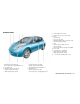
EXTERIOR FRONT 6. Power windows (P. 2-55) 7. Child safety rear door lock (P. 3-4) 8. Doors — Keys (P. 3-2) — Door locks (P. 3-4) — NISSAN Intelligent Key® system (P. 3-6) — Security system (P. 2-35) 9. Tires — Wheels and tires (P. 8-27, 9-6) — Flat tire (P. 6-3) — Tire Pressure Monitoring System (TPMS) (P. 2-16, 5-2) 10. Fog lights (if so equipped) — Switch operation (P. 2-45) — Bulb replacement (P. 8-22) 11. License plate installation (P. 9-10) 1. Charge port lid —Charging lid switch (P.
EXTERIOR REAR 6. Antenna — Satellite radio antenna (P. 4-57) 7. Rear combination lights — Bulb replacement (P. 8-22) 8. Rear hatch (P. 3-18) 1. Rear view camera (P. 4-3, 4-11) 2. Rear wiper and washer switch — Switch operation (P. 2-38) — Windshield-washer fluid (P. 8-11) 0-4 Illustrated table of contents 3. High-mounted stop light — Bulb replacement (P. 8-22) 4. Rear window defroster (P. 2-41) 5. Solar cell module (if so equipped) (P.
PASSENGER COMPARTMENT 6. Front heated seat switch (P. 2-47) 7. Front cup holders (P. 2-51) 8. Door armrest — Power window switch (P. 2-56) — Power door lock switch (P. 3-4) — Outside mirror remote control switch (P. 3-23) 9. Console box (P. 2-51) 10. Emergency tire puncture repair kit (P. 6-3) 11. Cargo area — Tonneau cover (if so equipped) (P. 2-51) — EVSE (Electric Vehicle Supply Equipment) (P. CH-27) 1. Room light (P. 2-58) 2. Sun visors (P. 3-22) 3. Map lights — Switch operation (P.
COCKPIT 1. TRIP switch for twin trip odometer (P. 2-5) 2. Trip computer switch (P. 2-22) 3. Instrument brightness control switch (P. 2-41) 4. Headlight, fog light and turn signal switch — Headlight (P. 2-42) — Turn signal light (P. 2-42) — Fog light (if so equipped) (P. 2-45) 5. Steering-wheel-mounted controls (left side) — Audio control (P. 4-56) — Bluetooth® Hands-Free Phone System control (P. 4-59) 6. Steering wheel — Power steering system (P. 5-19) — Horn (P. 2-46) — Driver’s supplemental air bag (P.
16. Vehicle Dynamic Control (VDC) OFF switch (P. 2-48) 17. Heated steering wheel switch (if so equipped) (P. 2-45) 18. Fuse box cover (P.
INSTRUMENT PANEL 10. Front passenger air bag status light, Approaching Vehicle Sound for Pedestrians (VSP) system warning light (P. 1-38, 2-14) 11. Auxiliary input jack (P. 4-38) 12. Power outlet (P. 2-50) 13. iPod® connector/USB connector (P. 4-38) 14. Push-button power switch (P. 5-7) 15. Hood release handle (P. 3-17) 1. Side vents (P. 4-22) 2. Meters and gauges (P. 2-5) 3.
METERS AND GAUGES This vehicle is equipped with an upper display and a lower display. 1. 2. 3. 4. 5. 6. 7. 8. Master warning lights (P. 2-18) ECO indicator (P. 2-10) Speedometer (P. 2-6) Clock (P. 2-11) Outside air temperature (P. 2-10) Turn signal/Hazard indicator light (P. 2-21) Li-ion battery capacity level gauge (P. 2-10) Li-ion battery available charge gauge (P. 2-9) 9. Driving range (P. 2-8) 10. Vehicle information display (P. 2-22) 11. READY to drive indicator light (P. 2-20) 12.
MOTOR COMPARTMENT 1. 2. 3. 4. 5. 6. 7. 0-10 Illustrated table of contents Brake fluid reservoir (P. 8-10) 12-volt battery (P. 8-12) Fuse holder (P. 8-17) Fuse/Fusible link holder (P. 8-17) Coolant reservoir cap (P. 8-8) Windshield-washer fluid reservoir (P. 8-11) Fuse/Fusible link holder (P.
WARNING AND INDICATOR LIGHTS Warning light Name Page 12-volt battery charge warning light 2-13 Anti-lock Braking System (ABS) warning light 2-14 2-14 BRAKE system warning light (yellow) 2-14 Electric shift control system warning light Name Page EV system warning light 2-16 Headlight warning light 2-16 Low battery charge warning light Approaching Vehicle Sound for Pedestrians (VSP) system warning light BRAKE warning light (red) Warning light Low tire pressure warning light Name Suppleme
Indicator light Name Page Plug-in indicator light 2-20 Power limitation indicator light 2-20 READY to drive indicator light 2-20 Security indicator light 2-20 Slip indicator light 2-21 Turn signal/hazard indicator lights 2-21 Vehicle Dynamic Control (VDC) OFF indicator 2-21 light 0-12 Illustrated table of contents
EV Overview The EV (Electric Vehicle) system . . . . . . . . . . . . .EV-2 Li-ion battery . . . . . . . . . . . . . . . . . . . . . . . . .EV-2 Driving with a discharged Li-ion battery . . . . . . .EV-3 Charging the 12-volt battery. . . . . . . . . . . . . .EV-5 Li-ion battery warmer (if so equipped) . . . . . . . .EV-5 High voltage precautions. . . . . . . . . . . . . . . . . .EV-7 High-voltage components . . . . . . . . . . . . . . .EV-7 Road accident precautions . . . . . . . . . . . . . . . .
THE EV (ELECTRIC VEHICLE) SYSTEM The LEAF is an electric vehicle. Some of the vehicle’s systems operate differently and have different operating characteristics than vehicles equipped with an internal combustion engine. It is important to carefully review the entire Owner’s Manual for this reason. The main difference is the LEAF is powered by electricity. The LEAF does not require and it is not capable of using gasoline like a vehicle powered by a traditional internal combustion engine.
NOTE: • If the outside temperature is −13°F (−25°C) or less, the Li-ion battery may freeze and it cannot be charged or provide power to run the vehicle. Move the vehicle to a warm location. • The capacity of the Li-ion battery in your vehicle to hold a charge will, like all such batteries, decrease with time and usage. As the battery ages and capacity decreases, this will result in a decrease from the vehicle’s initial mileage range.
on the vehicle information display at the same time to indicate low Li-ion battery charge: • The low battery charge warning light • The master warning light • “Li-ion battery level is Low” warning message is displayed on the vehicle information display • For additional information, refer to “Li-ion battery low charge warning” in the “Instruments and controls” section of this manual. • Messages are displayed on navigation system screen (if so equipped) 1 .
hicle. Contact Roadside assistance service shown in your NISSAN Warranty Information Booklet. For additional information, refer to “If the Li-ion battery becomes completely discharged” in the “In case of emergency” section of this manual. CHARGING THE 12-VOLT BATTERY The 12-volt battery is charged automatically using electricity stored in the Li-ion battery. 2. If the vehicle is driven and the Li-ion battery continues to discharge, the driving range on 2 .
The Li-ion battery warmer uses electrical power from an external source when a charger is connected to the vehicle. The Li-ion battery warmer uses electrical power from the Li-ion battery when the charger is not connected to the vehicle. NOTE: • Connect the charger to the vehicle and place the power switch in the OFF position when parking the vehicle if temperatures may go below -1°F (-17°C).
HIGH VOLTAGE PRECAUTIONS HIGH-VOLTAGE COMPONENTS WARNING • The EV (Electric Vehicle) system uses high voltage up to approximately DC 400 volt. The system can be hot during and after starting and when the vehicle is shut off. Be careful of both the high voltage and the high temperature. Follow the warning labels that are attached to the vehicle.
ROAD ACCIDENT PRECAUTIONS WARNING In case of a collision: • If your vehicle is drivable, pull your vehicle off the road, push the P (Park) position switch on the shift lever, apply the parking brake and turn the EV (Electric Vehicle) system off. • Check your vehicle to see if there are exposed high-voltage parts or cables. For their locations, refer to “High voltage components” in this section.
EV (ELECTRIC VEHICLE) CHARACTERISTICS NOTE: EMERGENCY SHUT-OFF SYSTEM The emergency shut-off system is activated and the high-voltage system automatically turns off in the following conditions: - Front and side collisions in which the air bags are deployed. - Certain rear collisions. - Certain EV (Electric Vehicle) system malfunctions For the above collisions and certain other EV system malfunctions, the READY to drive indicator light will turn off.
LIFE WITH AN EV (SCENE GUIDE) • Less deceleration is provided by the regenerative brake system when the Li-ion battery is fully charged. The regenerative brake is automatically reduced when the Li-ion battery is fully charged to prevent the Li-ion battery from becoming overcharged. The regenerative brake is also automatically reduced when the battery temperature is high/low (indicated by the red/blue zones on the Li-ion battery temperature gauge) to prevent Li-ion battery damage.
EV Overview EV-11
EV-12 EV Overview
BEFORE DRIVING YOUR VEHICLE (MODELS WITH NAVIGATION SYSTEM) The Li-ion battery charging status and the Li-ion battery warmer (if so equipped) operation can be checked using an internet enabled smart phone or personal computer at home. You may also choose to have SMS messages (text messages) sent to a cellular phone. Additionally, the heater and air conditioner of the vehicle can be set to operate using the Climate Ctrl. Timer function or A/C-heater remote function, if necessary.
Checking Li-ion battery charging status The Li-ion battery charge status can be checked on the NISSAN Data Center website via an internet enabled smart phone or personal computer. EV-14 EV Overview If the Li-ion battery is not sufficiently charged, you can start charging the Li-ion battery via the remote charge function. For additional information, refer to “Charging related remote function” in the “Charging” section of this manual.
Operating the climate control system before driving The vehicle heating and air conditioning system can be turned on via remote control with an internet enabled smart phone or personal computer. This allows the interior of the vehicle to be heated or cooled while the vehicle is charging. This reduces the load on the Li-ion battery while the vehicle is being driven and can help increase the vehicle driving range.
Notification of the Li-ion battery warmer operation (if so equipped) You can be notified with the status of the Li-ion battery warmer operation on the NISSAN Data Center website via an internet enabled smart phone or personal computer. EV-16 EV Overview When the power switch is in the OFF position and the charge connector is not connected, if the Li-ion battery warmer starts or stops, it notifies you to connect the charger to the vehicle.
5. Check the Li-ion battery level and the estimated driving range shown on the meter. For additional information, refer to “Driving range” in the “Instruments and controls” section of this manual. NOTE: STARTING YOUR VEHICLE 1. Depress the brake pedal. 2. Press the power switch. 3. Check that the READY to drive indicator light illuminates and the start up sound is audible. For additional information, refer to “Ready to drive indicator light” in the “Instruments and controls” section of this manual. 4.
DRIVING THE VEHICLE 1. Depress the brake pedal. 2. Release the parking brake. 3. Move the shift lever into the D (Drive) position. When released, the shift lever returns to its original center position. 4. Confirm that the vehicle is in the D (Drive) position. The indicator next to the “D” by the shift lever illuminates and “D” is displayed on the meter. EV-18 EV Overview 5. Release the brake pedal. 6. Depress the accelerator pedal and start driving.
NOTE: The regenerative brake converts the vehicle’s forward motion to electric power to help slow the vehicle. Use the ECO mode for maximum vehicle range and for city driving. The ECO mode helps reduce power consumption by reducing acceleration when compared to the same accelerator pedal position in the D (Drive) position. While the vehicle is being driven you can check your own ECO drive level on the ECO indicator.
If the low battery charge warning light illuminates, the Li-ion battery charge is too low for travel. For additional information, refer to ⬙Low battery charge warning light” in the “Instruments and controls” section of this manual. Charge the Li-ion battery as soon as possible.
Parking the vehicle 1. When stopping the vehicle, push the P (Park) position switch on the shift lever while depressing the brake pedal. Confirm that the vehicle is in the P (Park) position by checking the shift indicator located near the shift lever on the vehicle information display. 2. Apply the parking brake. 3. Push the power switch to the OFF position. 4. If a parking lot is equipped with charging facilities, charge the Li-ion battery as necessary.
NOTE: CHARGING AFTER DRIVING Charging the Li-ion battery When you return home, connect the vehicle to the charging station installed at your home using the normal charge connector. Charge the vehicle or set the charging timer function to have the vehicle charge at a specific time. For additional information, refer to “Charging timer” in the “Charging” section of this manual. 1. When the power switch is turned off, the settings of the charging timer, and the Climate Ctrl.
EFFICIENT USE OF YOUR VEHICLE RANGE The distance you can drive the vehicle (range) varies considerably depending upon available charge, weather, temperature, usage, battery age, topography, and driving style. Refer to the Monroney label (window sticker) for the official EPA range. Your actual range can vary, either initially or as the battery ages and with use over time.
• Release the accelerator pedal to slow down and do not apply the brakes when traffic and road conditions allow. – This vehicle is equipped with a regenerative brake system. The primary purpose of the regenerative brake system is to provide some power to recharge the Li-ion battery and extend driving range. A secondary benefit is “engine braking” that operates based on Li-ion battery conditions.
LI-ION BATTERY MAINTENANCE In addition to the regular maintenance recommended by NISSAN, the LEAF requires some special Li-ion battery inspections. • Refer to the NISSAN Warranty Information Booklet for significant limitations, exclusions and possible voiding of your warranty resulting from failure to have these necessary inspections, repairs and/or adjustments performed. • Refer to the NISSAN Service and Maintenance Guide for a detailed explanation of the Li-ion battery inspection and intervals.
ECO indicator: Lower display Power meter: This indicator provides instant information about how efficiently the vehicle is being operated. You can see how changing your driving style or operation of vehicle accessories affects power consumption. Li-ion battery temperature gauge: This meter displays the actual traction motor power consumption and the regenerative brake power provided to the Li-ion battery.
Driving range: Li-ion battery available charge gauge: Li-ion battery capacity level gauge: This indicator displays the estimated driving range (calculated based on a program that accounts for current driving style and operational conditions) that can be driven before recharging is necessary. This gauge displays the available Li-ion battery power remaining to drive the vehicle. This gauge displays the available capacity of the Li-ion battery remaining to store power.
3. 12-volt battery charge warning light 4. Plug-in indicator light 5. READY to drive indicator light 6. Power limitation indicator light 7. EV system warning light 8. Electric shift control system warning light 9. Brake system warning light (yellow) 10. Low battery charge warning light 11. Headlight warning light (if so equipped) 12.
For additional information, refer to “Driving the vehicle” in the “Starting and driving” section of this manual. The sound stops when the vehicle stops. The sound does not stop with the vehicle in the R (Reverse) position even if the vehicle stops. LED HEADLIGHT (LOW BEAM) (IF SO EQUIPPED) WARNING • If the sound cannot be heard, pedestrians may not notice the oncoming vehicle, which may cause an accident resulting in serious injury or death.
NOTE: The solar cell may not provide full charging power in the following situations. • When the intensity of sunlight is weak. • When the solar cell module is in the shade. • When the solar cell module is covered by leaves or dirt. DRIVING RANGE (IF SO EQUIPPED) Solar cell module on the rear spoiler SOLAR CELL MODULE (IF SO EQUIPPED) This vehicle uses a solar cell module to provide power to the 12-volt battery.
Charging Precautions on charging. . . . . . . . . . . . . Types of charge and how to charge the Li-ion battery . . . . . . . . . . . . . . . . . . . . . . . How to normal charge . . . . . . . . . . . . How to trickle charge. . . . . . . . . . . . . How to quick charge (if so equipped) . . . Charge connector lock switch . . . . . . . Charging methods . . . . . . . . . . . . . . . . Charging timer . . . . . . . . . . . . . . . . Immediate charge . . . . . . . . . . . . . . . . . . . .CH-2 . . . . . . . . .
PRECAUTIONS ON CHARGING WARNING • If you use any medical electric devices, such as an implantable cardiac pacemaker or an implantable cardiovascular defibrillator, check with the electric medical device manufacturer concerning the effects that charging may have on implanted devices before starting the charge operation. Charging may affect the operation.
– Do not store and use charging equipment in locations where the temperature is over 185°F (85°C). – Do not place the charging equipment close to a heater or other heat source. • Make sure the cap is closed on the charge port when charging is finished. If the charge port lid is closed when the cap is open, water or foreign materials may enter the charge port. • Do not charge when a vehicle body cover is in use. This may cause damage to the charge connector.
• If the vehicle will not be used for an extended period of time, charge the Li-ion battery using the long life mode once every three months. Do not operate the charging timer repeatedly while the charge connector is connected to the vehicle after the Li-ion battery charging is completed. Doing so may discharge the 12-volt battery. For additional information, refer to the long life mode charging method, in the “Charging timer” section of this manual.
TYPES OF CHARGE AND HOW TO CHARGE THE LI-ION BATTERY Charging CH-5
CH-6 Charging
This vehicle is an electric vehicle and it requires electricity to operate. The Li-ion battery is the only source of power to operate the vehicle. It is important to conserve power and plan your charging needs when you drive to avoid completely discharging the Li-ion battery and being unable to drive.
A vehicle equipped with a quick charge port is compatible with most CHAdeMO (Japanese industry standard) connectors on charging stations. Charging stations using this standard are UL certified and safe to use in the US. While supported by NISSAN, this connector may not become the US SAE standard. charging infrastructure to be developed in your area.
Li-ion battery tem- Estimated charge perature gauge time 10 or more seg- More than approxiE 䊊 ments illuminated mately 60 minutes NOTE: Charging time is typically limited to 60 minutes when using a quick charger. Press the start switch on the quick charger after it stops if additional charge time is necessary to reach an 80% charge. For additional information, refer to “How to quick charge” in this section. Power Limitation Mode This mode protects the health and operation of the vehicle’s Li-ion battery.
• Immediate charge, charging timer and remote charge (models with navigation system) can be performed in the normal charge mode. For additional information, refer to “Charging methods” in this section. • The Genuine NISSAN charging equipment communicates with the vehicle before Li-ion battery charging starts. If this communication does not occur because other equipment is used, the Li-ion battery will not charge.
HOW TO TRICKLE CHARGE WARNING To stop normal charge: 1. Ensure that the charge connector lock is not engaged. For additional information, refer to “Charge connector lock switch” in this section. 2. Press the button on the charge connector, release the lock and remove the charge connector from the charge port and properly store it. 3. After closing the charge port cap on the charge port, close the charge port lid. NOTE: To stop charging mid-charge, remove the charge connector. Charging automatically stops.
– The device has parts that may spark inside. Do not use it where gasoline, paint, or flammable liquids are used or stored. – Do not use if a malfunction occurs or if the charger has been damaged in any manner. Return to a NISSAN certified LEAF dealer for replacement. – The charger contains no user serviceable parts. Do not attempt to repair the charger, doing so will void your warranty.
To start trickle charging: A on the *:You can pass a rope through the hole 䊊 control box in order to hang it up while the Li-ion battery is charging. 1. Push the P (Park) position switch to place the vehicle in the P (Park) position and apply the parking brake. 2. When charging the Li-ion battery, place the power switch in the OFF position. When the power switch is in the ON position, the Li-ion battery will not start charging. 3. Open the charge port lid.
8. Connect the charge connector to the charge port. If it is connected normally, a beep will sound once. 9. If charging has started, or if the Li-ion battery is waiting for the charging timer, a beep will sound twice and the charging status indicator light display will change. For additional information, refer to “Charging status indicator lights” in this section. CH-14 Charging 10. When recharging outside, such as in your driveway, use a commercially available padA to prevent theft.
c. Place the charge cable and charge connector into the case in front of the EVSE (Electric Vehicle Supply Equipment) control box. WARNING Pass the lower side belt of the EVSE (Electric Vehicle Supply Equipment) case securely through the fastener on the bottom of the luggage board. If the case suddenly becomes loose, it may cause serious injury or death. 5. Store in its case. NOTE: Perform the following procedure to store the EVSE (Electric Vehicle Supply Equipment) in the case. a.
NOTE: Quick charging is possible (even several times a day) if the battery temperature is not near the red zone. If the battery temperature reaches the red zone, in order to protect the battery, quick charging is not allowed and the power limitation mode will be triggered.
NOTE: CAUTION • Be sure to insert the charge connector straight into the quick charge port right up to the base. Failure to do so may result in the Li-ion battery not charging or could cause damage to the charging equipment. 5. Grasp the lock lever and lock the charge connector. 6. Follow the instructions on the quick charge equipment to start charging. When the equipment is properly installed and ready to charge a beep sounds twice and the charging status indicator light will change.
CAUTION • As the quick charge connector is heavier in comparison to the other charge connectors, allowing it to drop could cause damage to the vehicle or charge connector or personal injury. When removing the connector, be sure to pull it out straight and as carefully as possible. To finish charging: 1. Confirm charging is stopped by looking at the indicators on the dash. The charge connector can be disconnected from the vehicle when charging is stopped. 2.
AUTO mode UNLOCK mode 1 of To select AUTO mode, push the AUTO side 䊊 the charge connector lock switch. The indicator 3 will illuminate. light on the switch 䊊 To select UNLOCK mode, return the charge connector lock switch to the level position. Make sure the indicator light on the switch turns off. When AUTO mode is selected, the charge connector is locked while charging is in process. The charge connector will be unlocked automatically when charging is complete.
NOTE: Unlock operation using charge port lid opener switch 1. Push the charge port lid opener switch. 2. The charging status indicator light flashes three times and a beep sounds three times. The charge connector lock is unlocked for 30 seconds. 3. After 30 seconds, the charge connector lock is locked. CH-20 Charging • Depending on the charging station, the lock mechanism established by local standards may not be compatible with your vehicle.
CHARGING METHODS CHARGING TIMER NOTE: Use charging timer to schedule when the Li-ion battery charges. The vehicle automatically begins charging at the scheduled times when the charge connector is connected to the vehicle. The timers do not need to be reset each time the Li-ion battery needs charging. Charging timer Use the charging timer to schedule when the Li-ion battery will be charged.
• When only the charging timer end time is set, the system automatically stops charging when the Li-ion battery charges to a full charge. Charging may stop before the scheduled end time. • If charging timer and the Climate Ctrl. Timer are operating at the same time due to an overlap of the timer settings, you can prioritize which function receives electrical power first. For additional information, refer to “Leaf Navigation System Owner’s Manual”.
• +: Touch or touch and hold to increase the time. • x: Touch to delete the numbers entered in the corresponding column. 4. Touch the keys to set the days of the week you wish to start charging. 5. Touch to save the settings. Timer Charge setting screen: Two different timer settings can be registered (one on the left side and another on the right side of the screen). 1. Touch to turn on/of the timer. The indicator light will turn on when the timer setting is turned on. 2.
• When the Charging Timer and the Climate Ctrl. Timer are set at the same time, the charging start time moves to an earlier time. • Depending on the Li-ion battery condition and the power source status, charging may end earlier than the charging end time. This is not a malfunction. A on the left side of 1. Push the switch 䊊 the combination meter panel. B to highlight “Chargswitch 䊊 2. Push the ing Timer” on the vehicle information display and then push the switch. CH-24 Charging 3.
IMMEDIATE CHARGE When a charging timer is not turned on, charging automatically starts when a normal or trickle charge connector is connected to the vehicle. Use the immediate charge mode anytime you want to start charging when a charging timer is turned on by performing the following: 1. Place the power switch in the OFF position. To turn the timer on or off, use the switch to highlight “On” or “Off” and then push the switch.
NOTE: 2. Press the immediate charge switch. 3. Connect the normal or trickle charge cable when the charging status indicator light changes to display immediate charge mode. For additional information, refer to “Charging status indicator lights” in this section. CH-26 Charging • You have 15 minutes to connect a normal or trickle charge connector to the vehicle after the immediate charge switch is pressed.
CHARGING RELATED INDICATOR LIGHTS NOTE: • Establishing the NissanConnectSM EV service is necessary before using this service. For additional information, refer to the LEAF Navigation System Owner’s Manual. • To check the Li-ion battery charging status using an internet enabled smart phone or personal computer, the following conditions must be met: – The vehicle must be located in a cellular phone coverage area. – The cellular phone must be located in an area with cellular phone coverage.
When the normal charge connector lock is unlocked 1 to 䊊 3 , will flash and All of the indicator lights, 䊊 a beep will sound three times when the normal charge connector lock switch on the Intelligent Key or the charge port lid opener switch is pushed. When the normal charge connector is connected incorrectly 1 to 䊊 3 , will flash and All of the indicator lights, 䊊 a beep will sound three times within 30 seconds when the charge connector is connected incorrectly to the normal charge port.
When charging When the Li-ion battery is being charged, the charging status indicator lights will change depending on the amount the Li-ion battery is charged. *: This value is also displayed by the illumination of segments of the Li-ion battery available charge gauge on the instrument panel. When fully charged All of the indicator lights 䊊 to 䊊 illuminate when the Li-ion battery is fully charged to the selected charging mode level.
The indicator will also flash for up to 5 minutes if the electrical power to the EVSE is interrupted during charging. Charging will restart automatically when the electrical power to the EVSE is restored if the charging connector is connected. The charge start beep will not sound when charging restarts. The indicator will also flash when the following systems are operating: • Climate Ctrl.
READY CHARGE FAULT 䡩 䡩 䡩 Status and action to be taken Every time the EVSE plug is connected to an outlet, all indicator lights illuminate for 0.5 seconds. After initial processing is completed, when the EVSE is not connected to the vehicle, or the EVSE is connected to the vehicle but charging is not being performed. 䡩 쏹 쏹 䡩 䡩 쏹 While the battery is being charged When the ground cable is disconnected Check the grounding of the outlet being used.
CHARGING TROUBLESHOOTING GUIDE Symptom Possible cause The vehicle power switch is in the ON position. Possible solution Before charging, place the vehicle power switch in the OFF position. Both the normal charge connector and the quick charge (if so equipped) connector are connected The normal charge connector and the quick charge connector cannot be connected at the same time. at the same time.
Symptom Charging timer cannot be performed. Possible cause Possible solution The charge cable is not connected. Connect the charge cable. The time on the clock is wrong. The charging timer function does not start charging based on the clock located on the upper display. Confirm that the date and time shown on the charging timer screen are the same as the GPS time and date. If the 12-volt battery is discharged or if the Li-ion battery is disconnected, the time setting must be updated.
Symptom Normal charge stops in the middle of charging. Possible cause Possible solution There is no power coming from the outlet. There may have been a electrical power failure, or the breaker may have failed. Charging will resume when the power source is reset. The charge cable has been disconnected. Check that the charge cable has not been disconnected.
1 Safety–Seats, seat belts and supplemental restraint system Seats . . . . . . . . . . . . . . . . . . . . . . . . . . . Front seats . . . . . . . . . . . . . . . . . . . . . . Rear seats . . . . . . . . . . . . . . . . . . . . . . Head restraints/headrests . . . . . . . . . . . . . . . Adjustable head restraint/headrest components Non-adjustable head restraint/headrest components . . . . . . . . . . . . . . . . . . . . . Remove. . . . . . . . . . . . . . . . . . . . . . . . Install . . . . . . . . . . . .
SEATS WARNING • Do not ride in a moving vehicle when the seatback is reclined. This can be dangerous. The shoulder belt will not be against your body. In an accident, you could be thrown into it and receive neck or other serious injuries. You could also slide under the lap belt and receive serious internal injuries. • For the most effective protection when the vehicle is in motion, the seat should be upright.
FRONT SEATS Front manual seat adjustment Your vehicle seats can be adjusted manually. For additional information about adjusting the seats, refer to the steps outlined in this section. Forward and backward: Pull the bar up and hold it while sliding the seat forward or backward to the preferred position. Release the bar to lock the seat in position. Reclining: Seat lifter (driver’s seat): To recline the seatback, pull the lever up and lean back.
• Properly secure all cargo with ropes or straps to help prevent it from sliding or shifting. Do not place cargo higher than the seatbacks. In a sudden stop or collision, unsecured cargo could cause personal injury. • When returning the seatbacks to the upright position, be certain they are completely secured in the latched position. If they are not completely secured, passengers may be injured in an accident or sudden stop.
HEAD RESTRAINTS/HEADRESTS WARNING Head restraints/headrests supplement the other vehicle safety systems. They may provide additional protection against injury in certain rear end collisions. Adjustable head restraints/ headrests must be adjusted properly, as specified in this section. Check the adjustment after someone else uses the seat. Do not attach anything to the head restraint/headrest stalks or remove the head restraints/headrests. Do not use the seat if the head restraint/headrest has been removed.
ADJUSTABLE HEAD RESTRAINT/ HEADREST COMPONENTS 1. 2. 3. 4. Removable head restraint/headrest Multiple notches Lock knob Stalks NON-ADJUSTABLE HEAD RESTRAINT/HEADREST COMPONENTS REMOVE 1. 2. 3. 4. 1. Pull the head restraint/headrest up to the highest position. 2. Push and hold the lock knob. 3. Remove the head restraint/headrest from the seat. 4. Store the head restraint/headrest properly in a secure place so it is not loose in the vehicle. 5.
INSTALL 1. Align the head restraint/headrest stalks with the holes in the seat. Make sure the head restraint/headrest is facing the correct direc1 tion. The stalk with the notch (notches) 䊊 must be installed in the hole with the lock 2 . knob 䊊 2. Push and hold the lock knob and push the head restraint/headrest down. 3. Properly adjust the head restraint/headrest before an occupant uses the seating position.
SEAT BELTS PRECAUTIONS ON SEAT BELT USAGE If you are wearing your seat belt properly adjusted, and you are sitting upright and well back in your seat with both feet on the floor, your chances of being injured or killed in an accident and/or the severity of injury may be greatly reduced. NISSAN strongly encourages you and all of your passengers to buckle up every time you drive, even if your seating position includes a supplemental air bag. Raise Lower To raise the head restraint/headrest, pull it up.
Safety–Seats, seat belts and supplemental restraint system 1-9
WARNING • Every person who drives or rides in this vehicle should use a seat belt at all times. Children should be in the rear seats and in an appropriate restraint. • The seat belt should be properly adjusted to a snug fit. Failure to do so may reduce the effectiveness of the entire restraint system and increase the chance or severity of injury in an accident. Serious injury or death can occur if the seat belt is not worn properly. • Always route the shoulder belt over your shoulder and across your chest.
PREGNANT WOMEN NISSAN recommends that pregnant women use seat belts. The seat belt should be worn snug, and always position the lap belt as low as possible around the hips, not the waist. Place the shoulder belt over your shoulder and across your chest. Never put the lap/shoulder belt over your abdominal area. Contact your doctor for specific recommendations. INJURED PERSONS SEAT BELT WARNING LIGHT Both the driver’s and passenger’s front seats are equipped with a seat belt warning light.
The front passenger seat and the rear seating positions three-point seat belts have two modes of operation: • Emergency Locking Retractor (ELR) • Automatic Locking Retractor (ALR) The ELR mode allows the seat belt to extend and retract to allow the driver and passengers some freedom of movement in the seat. The ELR locks the seat belt when the vehicle slows down rapidly or during certain impacts. The ALR mode (child restraint mode) locks the seat belt for child restraint installation.
The ALR mode should be used only for child restraint installation. During normal seat belt use by an occupant, the ALR mode should not be activated. If it is activated, it may cause uncomfortable seat belt tension. It can also change the operation of the front passenger air bag. For additional information, refer to “Front passenger air bag and status light” in this section.
WARNING • After adjustment, release the adjustment button and then try to move the shoulder belt anchor up and down to make sure that it is securely fixed in position. • The shoulder belt anchor height should be adjusted to the position that is best for you. Failure to do so may reduce the effectiveness of the entire restraint system and increase the chance or severity of injury in an accident.
SEAT BELT EXTENDERS SEAT BELT MAINTENANCE If, because of body size or driving position, it is not possible to properly fit the lap/shoulder belt and fasten it, an extender that is compatible with the installed seat belts is available for purchase. The extender adds approximately 8 in (200 mm) of length and may be used for either the driver or front passenger seating position. See a NISSAN certified LEAF dealer for assistance with purchasing an extender if an extender is required.
CHILD SAFETY WARNING Do not allow children to play with the seat belts. Most seating positions are equipped with Automatic Locking Retractor (ALR) mode seat belts. If the seat belt becomes wrapped around a child’s neck with the ALR mode activated, the child can be seriously injured or killed if the seat belt retracts and becomes tight. This can occur even if the vehicle is parked. Unbuckle the seat belt to release the child.
INFANTS LARGER CHILDREN Infants up to at least 1 year old should be placed in a rear-facing child restraint. NISSAN recommends that infants be placed in child restraints that comply with Federal Motor Vehicle Safety Standards or Canadian Motor Vehicle Safety Standards. You should choose a child restraint that fits your vehicle and always follow the manufacturer’s instructions for installation and use.
CHILD RESTRAINTS WARNING Never let a child stand or kneel on any seat and do not allow a child in the cargo areas. The child could be seriously injured or killed in an accident or sudden stop. If you answered no to any of these questions, the child should remain in a booster seat using a three-point type seat belt. PRECAUTIONS ON CHILD RESTRAINTS NOTE: Laws in some communities may follow different guidelines.
– The child restraint must be used and installed properly. Always follow all of the child restraint manufacturer’s instructions for installation and use. – Infants and children should never be held on anyone’s lap. Even the strongest adult cannot resist the forces of a collision. – Do not put a seat belt around both a child and another passenger. – NISSAN recommends that all child restraints be installed in the rear seat.
Several manufacturers offer child restraints for infants and small children of various sizes. When selecting any child restraint, keep the following points in mind: • Choose only a restraint with a label certifying that it complies with Federal Motor Vehicle Safety Standard 213 or Canadian Motor Vehicle Safety Standard 213. • Check the child restraint in your vehicle to be sure it is compatible with the vehicle’s seat and seat belt system.
seat belt (not the lower anchors) to install the child restraint. Be sure to follow the child restraint manufacturer’s instructions for installation. The LATCH lower anchor points are provided to install child restraints in the rear outboard seating positions only. Do not attempt to install a child restraint in the center position using the LATCH lower anchors.
Top tether anchor WARNING LATCH webbing-mounted attachment Installing child restraint LATCH lower anchor attachments LATCH compatible child restraints include two rigid or webbing-mounted attachments that can be connected to two anchors located at certain seating positions in your vehicle. With this system, you do not have to use a vehicle seat belt to secure the child restraint. Check your child restraint for a label stating that it is compatible with the LATCH system.
REAR-FACING CHILD RESTRAINT INSTALLATION USING LATCH • Child restraint anchorages are designed to withstand only those loads imposed by correctly fitted child restraints. Under no circumstances are they to be used to attach adult seat belts, or other items or equipment to the vehicle. Doing so could damage the child restraint anchorages. The child restraint will not be properly installed using the damaged anchorage, and a child could be seriously injured or killed in a collision.
Rear-facing webbing-mounted — step 2 2. Secure the child restraint anchor attachments to the LATCH lower anchors. Check to make sure that the LATCH attachment is properly attached to the lower anchors. Rear-facing rigid-mounted — step 2 1-24 Safety–Seats, seat belts and supplemental restraint system Rear-facing — step 3 3. For child restraints that are equipped with webbing-mounted attachments, remove any additional slack from the anchor attachments.
5. Check to make sure that the child restraint is properly secured prior to each use. If the child restraint is loose, repeat steps 2 through 4. REAR-FACING CHILD RESTRAINT INSTALLATION USING THE SEAT BELTS Do not use the lower anchors if the combined weight of the child and child restraint exceeds 65 lbs (29.5 kg). If the combined weight of the child and child restraint is greater than 65 lbs (29.5 kg), use the vehicle’s seat belt (not the lower anchors) to install the child restraint.
Rear-facing — step 1 Follow these steps to install a rear-facing child restraint using the vehicle seat belt in the rear seats: 1. Child restraints for infants must be used in the rear-facing direction and therefore must not be used in the front seat. Position the child restraint on the seat. Always follow the child restraint manufacturer’s instructions. Rear-facing — step 2 2. Route the seat belt tongue through the child restraint and insert it into the buckle until you hear and feel the latch engage.
Rear-facing — step 4 4. Allow the seat belt to retract. Pull up on the shoulder belt to remove any slack in the belt. Rear-facing — step 5 5. Remove any additional slack from the child restraint. Press downward and rearward firmly in the center of the child restraint with your hand to compress the vehicle seat cushion and seatback while pulling up on the seat belt. Rear-facing — step 6 6. After attaching the child restraint, test it before you place the child in it.
7. Check to make sure that the child restraint is properly secured prior to each use. If the seat belt is not locked, repeat steps 1 through 6. After the child restraint is removed and the seat belt fully retracted, the ALR mode (child restraint mode) is canceled. FORWARD-FACING CHILD RESTRAINT INSTALLATION USING LATCH For additional information, refer to all Warnings and Cautions in “Child safety” and “Child restraints” sections of this manual before installing a child restraint.
If the seating position does not have an adjustable head restraint/headrest and it is interfering with the proper child restraint fit, try another seating position or a different child restraint. Forward-facing — step 4 4. For child restraints that are equipped with webbing-mounted attachments, remove any additional slack from the anchor attachments.
Rear bench seat 7. Check to make sure the child restraint is properly secured prior to each use. If the child restraint is loose, repeat steps 1 through 6. OUTBOARD SEATING POSITIONS Installing top tether strap 1 Top tether strap 䊊 2 Tether anchor point 䊊 The child restraint top tether strap must be used when installing the child restraint with the LATCH lower anchor attachments. First, secure the child restraint with the LATCH lower anchors (rear bench outboard seating positions only).
CENTER SEATING POSITION 1. Position the top tether strap 䊊 over the seatback. 2. Secure the tether strap to the tether anchor 2 on the bottom of the seatback bepoint 䊊 hind the child restraint. 3. Tighten the tether strap according to the manufacturer’s instructions to remove any slack. 1 If you have any questions when installing a top tether strap, consult a NISSAN certified LEAF dealer for details.
Follow these steps to install a forward-facing child restraint using the vehicle seat belt in the rear seat or in the front passenger seat: 1. If you must install a child restraint in the front seat, it should be placed in the forward-facing direction only. Move the seat to the rearmost position. Child restraints for infants must be used in the rear-facing direction and therefore must not be used in the front seat. 2. Position the child restraint on the seat.
Forward-facing — step 5 5. Allow the seat belt to retract. Pull up on the shoulder belt to remove any slack in the belt. Forward-facing — step 6 6. Remove any additional slack from the seat belt. Press downward and rearward firmly in the center of the child restraint with your knee to compress the vehicle seat cushion and seatback while pulling up on the seat belt. 7. Tighten the tether strap according to the manufacturer’s instructions to remove any slack. Forward-facing — step 8 8.
9. Check to make sure the child restraint is properly secured prior to each use. If the seat belt is not locked, repeat steps 2 through 8. 10. If the child restraint is installed on the front passenger seat, push the power switch to the ON position. The front passenger air bag status light should illuminate. If this light does not illuminate, refer to “Front passenger air bag and status light” in this section. Move the child restraint to another seating position.
Rear bench seat OUTBOARD SEATING POSITIONS 1. Remove the head restraint/headrest and store it in a secure place. Be sure to reinstall the head restraint/headrest when the child restraint is removed. For additional information about head restraint/headrest adjustment, removal and installation, refer to “Head restraints/headrestsⴖ in this section. 1 over the 2. Position the top tether strap 䊊 seatback. 3.
Booster seats of various sizes are offered by several manufacturers. When selecting any booster seat, keep the following points in mind: • Choose only a booster seat with a label certifying that it complies with Federal Motor Vehicle Safety Standard 213 or Canadian Motor Vehicle Safety Standard 213. • Check the booster seat in your vehicle to be sure it is compatible with the vehicle’s seat and seat belt system. • Make sure the child’s head will be properly supported by the booster seat or vehicle seat.
Booster seat installation WARNING To avoid injury to a child, do not use the lap/shoulder belt Automatic Locking Retractor (ALR) mode when using a booster seat with the seat belts. For additional information, refer to all Warnings and Cautions in “Child safety”, “Child restraints” and “Booster seats” sections of this manual before installing a child restraint. Follow these steps to install a booster seat on the rear seat or in the front passenger seat: Front passenger seat 1.
If the seating position does not have an adjustable head restraint/headrest and it is interfering with the proper booster seat fit, try another seating position or a different booster seat. 4. Position the lap portion of the seat belt low and snug on the child’s hips. Be sure to follow the booster seat manufacturer’s instructions for adjusting the seat belt routing. 5. Pull the shoulder belt portion of the seat belt toward the retractor to take up extra slack.
Roof-mounted curtain side-impact supplemental air bag system This system can help cushion the impact force to the head of occupants in front and rear outboard seating positions in certain side impact collisions. In a side impact, the curtain air bags are designed to inflate on the side where the vehicle is impacted. The SRS is designed to supplement the crash protection provided by the driver and passenger seat belts and are not a substitute for them.
WARNING • The front air bags ordinarily will not inflate in the event of a side impact, rear impact, rollover or lower severity frontal collision. Always wear your seat belts to help reduce the risk or severity of injury in various kinds of accidents. • The front passenger air bag will not inflate if the passenger air bag status light is lit or if the front passenger seat is unoccupied. For additional information, refer to “Front passenger air bag and status light” in this section.
WARNING • Never let children ride unrestrained or extend their hands or face out of the window. Do not attempt to hold them in your lap or arms. Some examples of dangerous riding positions are shown in the illustrations. • Children may be severely injured or killed when the front air bags, side air bags or curtain air bags inflate if they are not properly restrained. Pre-teens and children should be properly restrained in the rear seat, if possible.
Do not lean against doors or windows. WARNING Front seat-mounted side-impact supplemental air bags and roof-mounted curtain side-impact supplemental air bags: • The side air bags and curtain air bags ordinarily will not inflate in the event of a frontal impact, rear impact, rollover or lower severity side collision. Always wear your seat belts to help reduce the risk or severity of injury in various kinds of accidents.
• The seat belts, the side air bags and curtain air bags are most effective when you are sitting well back and upright in the seat. The side air bag and curtain air bag inflate with great force. Do not allow anyone to place their hand, leg or face near the side air bag on the side of the seatback of the front seat or near the side roof rails. Do not allow anyone sitting in the front seats or rear outboard seats to extend their hand out of the window or lean against the door.
NISSAN ADVANCED AIR BAG SYSTEM (FRONT SEATS) WARNING To ensure proper operation of the front passenger’s NISSAN Advanced Air Bag System, please observe the following items. • Do not allow a passenger in the rear seat to push or pull on the seatback pocket. • Do not place heavy loads heavier than 9 lb (4 kg) on the seatback, head restraint/headrest or in the seatback pocket. • Do not store luggage behind the seat that can press into the seatback.
the crash severity. Additionally, the front passenger air bag may be automatically turned OFF under some conditions, depending on the weight detected on the passenger seat and how the seat belt is used. If the front passenger air bag is OFF, the passenger air bag status light will be illuminated (if the seat is unoccupied, the light will not be illuminated, but the air bag will be off). For additional information, refer to “Front passenger air bag and status light” in this section.
Front passenger air bag status light Status light The front passenger seat is equipped with an occupant classification sensor (weight sensor) that turns the front passenger air bag on or off depending on the weight applied to the front passenger seat. The status of the front passenger air bag (ON or OFF) is indicated by the front passenger air bag status light which is located on the instrument panel.
passenger air bag to be automatically turned OFF. For small adults it may be turned OFF, however if the occupant takes his/her weight off the seat cushion (for example, by not sitting upright, by sitting on an edge of the seat, or by otherwise being out of position), this could cause the sensors to turn the air bag OFF. Always be sure to be seated and wearing the seat belt properly for the most effective protection by the seat belt and supplemental air bag.
If a malfunction occurs in the front passenger air bag system, the supplemental air bag warning light , located in the meter and gauges area of the instrument panel, will blink. Have the system checked by a NISSAN certified LEAF dealer. Normal operation In order for the occupant classification sensor system to classify the front passenger based on weight, please follow the precautions and steps outlined below: Precautions • Make sure that there are no objects weighing over 2.
NOTE: A system check will be performed during which the front passenger air bag status light will remain lit for about 7 seconds initially. If the light is ON after this, the vehicle should be checked by a NISSAN certified LEAF dealer as soon as possible. 2. If the light is ON with an adult occupying the front passenger seat: • Occupant is a small adult — the air bag light is functioning as intended. The front passenger air bag is suppressed.
the above conditions. Restart the vehicle and wait 1 minute. NOTE: A system check will be performed during which the front passenger air bag status light will remain lit for about 7 seconds initially. If the light is still OFF after this, the small adult, child or child restraint should be repositioned in the rear seat and the vehicle should be checked by a NISSAN certified LEAF dealer as soon as possible.
• No unauthorized changes should be made to any components or wiring of the seat belt system. This may affect the front air bag system. Tampering with the seat belt system may result in serious personal injury. • Work on and around the front air bag system should be done by a NISSAN certified LEAF dealer. Installation of electrical equipment should also be done by a NISSAN certified LEAF dealer. The Supplemental Restraint System (SRS) wiring harnesses* should not be modified or disconnected.
The seat belts should be correctly worn and the driver and passenger seated upright as far as practical away from the side air bags. Rear seat passengers should be seated as far away as practical from the door finishers and side roof rails. The side air bags and curtain air bags inflate quickly in order to help protect the occupants in the outboard seating positions.
SEAT BELT WITH PRETENSIONER(S) (FRONT SEATS) WARNING • The pretensioner(s) cannot be reused after activation. They must be replaced together with the retractor and buckle as a unit. • If the vehicle becomes involved in a collision but pretensioner(s) are not activated, be sure to have the pretensioner system checked and, if necessary, replaced by a NISSAN certified LEAF dealer. • No unauthorized changes should be made to any components or wiring of the pretensioner system.
When the power switch is in the ON position, the supplemental air bag warning light illuminates for about 7 seconds and then turns off. This means the system is operational. SUPPLEMENTAL AIR BAG WARNING LABELS A. Supplemental front-impact air bag system warning labels SRS air bag warning labels The warning labels are located on the surface of the sun visors.
WARNING If the supplemental air bag warning light is on, it could mean that the front air bag, side air bag, curtain air bag and/or pretensioner systems will not operate in an accident. To help avoid injury to yourself or others, have your vehicle checked by a NISSAN certified LEAF dealer as soon as possible. Repair and replacement procedure The front air bags, side air bags, curtain air bags and pretensioner(s) are designed to activate on a one-time-only basis.
NOTES 1-56 Safety–Seats, seat belts and supplemental restraint system
2 Instruments and controls Cockpit . . . . . . . . . . . . . . . . . . . . . . Instrument panel. . . . . . . . . . . . . . . . . Meters and gauges . . . . . . . . . . . . . . . Speedometer and odometer. . . . . . . . Li-ion battery temperature gauge . . . . . Power meter . . . . . . . . . . . . . . . . . Driving range. . . . . . . . . . . . . . . . . Li-ion battery available charge gauge . . Li-ion battery capacity level gauge . . . . Outside air temperature . . . . . . . . . . ECO indicator . . . . . . .
Seatback Pocket (if so equipped). Sunglasses holder. . . . . . . . . . Glove box. . . . . . . . . . . . . . . Console box . . . . . . . . . . . . . Tonneau cover (if so equipped) . . Stowing golf bags . . . . . . . . . . Windows . . . . . . . . . . . . . . . . . Power windows . . . . . . . . . . . Interior lights . . . . . . . . . . . . . . . Map lights . . . . . . . . . . . . . . Room light . . . . . . . . . . . . . . . . . . . . . . . . . . . . . . . . . . . . . . . . . . . . . . . . . . . . . . . . .
COCKPIT 6. Steering wheel — Power steering system (P. 5-19) — Horn (P. 2-46) — Driver’s supplemental air bag (P. 1-38) 7. Wiper and washer switch (P. 2-38) 8. Steering-wheel-mounted controls (right side) — Cruise control switches (P. 5-16) — ECO button (P. 2-47) 9. Console box (P. 2-51) 10. Shift lever (P. 5-12) 11. Front heated seat switch (P. 2-47) 12. Tilting steering wheel lever (P. 3-21) 13. Charge port lid switch (P. 3-19) 14. Charge connector lock switch (P. CH-5) 15. Charge timer OFF switch (P.
INSTRUMENT PANEL 9. Front passenger air bag status light, Approaching Vehicle Sound for Pedestrians (VSP) system warning light (P. 1-38, 2-14) 10. Auxiliary input jack (P. 4-38) 11. Power outlet (P. 2-50) 12. Heater and air conditioner control (P. 4-22 ) 13. iPod® connector/USB connector (P. 4-38) 14. Push-button power switch (P. 5-7) 15. Hood release handle (P. 3-17) 1. Side vents (P. 4-22) 2. Meters and gauges (P. 2-5) 3.
METERS AND GAUGES 11. READY to drive indicator light (P. 2-20) 12. ECO mode indicator light —ECO switch (P. 2-47 — Odometer/twin trip odometer (P. 2-6) — Trip computer (P. 2-27) — Shift “P” warning (P. 2-26) — Indicator for timer (P. 2-35) 13. Power meter (P. 2-7) 14. Warning and indicator lights (P. 2-12) 15. Li-ion battery temperature gauge (P. 2-6) This vehicle is equipped with an upper display and a lower display. 1. 2. 3. 4. Master warning lights (P. 2-18) ECO indicator (P. 2-10) Speedometer (P.
Changing the display: 3 located on the left Pushing the TRIP switch 䊊 side of the combination meter panel changes the display as follows: TRIP A → TRIP B → TRIP A For additional information about the vehicle information display, refer to “Vehicle information display” in this section. Resetting the trip odometer: 3 for approximately 1 Pushing the TRIP switch 䊊 second resets the trip odometer to zero.
• If the outside temperature is extremely low, the Li-ion temperature gauge may not display a temperature reading. The vehicle may not be able to be put in the READY to drive mode. Contact a NISSAN certified LEAF dealer. NOTE: POWER METER • If the display indicates that the temperature of the Li-ion battery is near the red zone end of the normal range, reduce vehicle speed to decrease the temperature.
The Power meter also indicates if the power provided to the motor is limited or if regenerative braking is limited. When power or regenerative braking is limited, the circles on the display 2 . change from a double circle to a single circle 䊊 NOTE: Regenerative braking is automatically reduced when the Li-ion battery is fully charged to prevent the Li-ion battery from becoming overcharged.
minates, there is a very small reserve of Li-ion battery charge remaining. NOTE: LI-ION BATTERY AVAILABLE CHARGE GAUGE 1 indicates the approximate availThe gauge 䊊 able Li-ion battery charge to run the vehicle. Charge the Li-ion battery before the display reaches the bottom line. The low battery charge warning light illuminates when the Li-ion battery available charge gauge is getting low. Charge as soon as it is convenient, preferably before the display reaches the bottom line.
LI-ION BATTERY CAPACITY LEVEL GAUGE This gauge indicates the amount of charge the Li-ion battery is capable of storing. When the capacity of the Li-ion battery decreases with age and usage, the level of the gauge will also decrease. 2-10 Instruments and controls OUTSIDE AIR TEMPERATURE ECO INDICATOR The outside air temperature is displayed in °F or °C. The ECO indicator displays how economically the vehicle is being operated.
For models with navigation system: • Time the vehicle is not moving while the vehicle is in the READY to drive mode and accessories are on. This clock is synchronized with the clock displayed on the navigation system screen. For additional information, refer to the LEAF Navigation System Owner’s Manual. Instant ECO driving level 1 is displayed by The instant ECO driving level 䊊 the number of bars that increase (more economical driving) or decrease (less economical driving) depending on vehicle operation.
WARNING LIGHTS, INDICATOR LIGHTS AND AUDIBLE REMINDERS or or 12-volt battery charge warning light Low battery charge warning light Front passenger air bag status light Anti-lock Braking System (ABS) warning light Low tire pressure warning light High beam indicator light (blue) Approaching Vehicle Sound for Pedestrians (VSP) system warning light Master warning light (red/yellow) Plug-in indicator light BRAKE system warning light (yellow) Power steering warning light Power limitation indicator l
Headlight warning light CHECKING LIGHTS With all doors closed, apply the parking brake, fasten the seat belts and place the power switch for Leaf to the ON position without starting the engine. The following lights (if so equipped) will come on: , The following lights (if so equipped) come on briefly and then turn off: (yellow), , , , , (red), , , , If any light does not come on or operate in a way other than described, it may indicate a burned-out bulb and/or a system malfunction.
• The DC/DC converter system may not be functioning properly if the 12-volt warning light illuminates continuously when the power switch is in the READY to drive position. Do not charge the 12-volt battery while this warning light is illuminated. It may lead to a malfunction of the DC/DC converter system. Contact a NISSAN certified LEAF dealer.
cooperative regenerative brake and/or the electronically driven intelligent brake systems are not functioning properly. Have the system checked by a NISSAN certified LEAF dealer. If the BRAKE warning light (red) also illuminates, stop the vehicle immediately and contact a NISSAN certified LEAF dealer. For additional information, refer to“Brake system” in the “Starting and driving” section of this manual.
• Pressing the brake pedal when the power switch position is not in the ON or READY to drive position and/or low brake fluid level may increase the stopping distance and braking will require greater pedal effort as well as pedal travel. • If the brake fluid level is below the minimum or MIN mark on the brake fluid reservoir, do not drive until the brake system has been checked at a NISSAN certified LEAF dealer.
When the low tire pressure warning light illuminates, you should stop and adjust the tire pressure to the recommended COLD tire pressure shown on the Tire and Loading Information label. The low tire pressure warning light does not automatically turn off when the tire pressure is adjusted. After the tire is inflated to the recommended pressure, the vehicle must be driven at speeds above 16 mph (25 km/h) to activate the TPMS and turn off the low tire pressure warning light.
• Since the spare tire is not equipped with the TPMS, when a wheel is replaced, the TPMS will not function and the low tire pressure warning light will flash for approximately 1 minute. The light will remain on after 1 minute. Contact a NISSAN certified LEAF dealer as soon as possible for tire replacement and/or system resetting. • Replacing tires with those not originally specified by NISSAN could affect the proper operation of the TPMS.
For additional information, refer to “Seat belts” in the “Safety — Seats seat belts and supplemental restraint system” section of this manual for precautions on seat belt usage. Supplemental air bag warning light For additional information, refer to “Supplemental restraint system (SRS)” in the “Safety — Seats seat belts and supplemental restraint system” section of this manual.
Plug-in indicator light This light illuminates when the charge connector is connected to the vehicle and blinks during charging. NOTE: If the charge connector is connected to the vehicle, the power switch can not be placed in the READY to drive position. Power limitation indicator light When the power limitation indicator light is illuminated, the power provided to the traction motor is reduced.
If the security system is malfunctioning, this light will remain on while the power switch is in the ON position. For additional information, refer to “Security systems” in this section. Slip indicator light This indicator will blink when the VDC system or the traction control system is operating, thus alerting that the vehicle is nearing its traction limits. The road surface may be slippery. You may feel or hear the system working; this is normal.
VEHICLE INFORMATION DISPLAY For additional information about the cruise control, refer to “Cruise control” in the “Starting and driving” section of this manual. Power switch reminder chime The power switch reminder chime will sound when the driver’s door is opened while the power switch is in the ON or READY to drive position. Push the power switch to the OFF position.
INDICATORS FOR OPERATION 1. READY to drive position operation indicator This indicator appears while the vehicle is in the P (Park) position. This indicator means that the EV system will start when the power switch is pressed with the brake pedal depressed. 2. Key is not detected warning This warning appears in either of the following conditions.
4. EV system operation for discharged Intelligent Key® system indicator This indicator appears when the Intelligent Key battery is running out of power and when the Intelligent Key system and vehicle are not communicating normally. If this indicator appears, touch the power switch with the Intelligent Key while depressing the brake pedal. For additional information, refer to “NISSAN Intelligent Key® battery discharge” in the “Starting and driving” section of this manual. 5.
12. Remove charge connector warning This warning appears when the power switch is in the ACC or ON position and if the power switch is pushed to the READY to drive position with the brake pedal depressed, while the charge connector is inserted to the vehicle. Remove the charge connector. 13. Electric shift control system warning This message appears if there is a malfunction in the electric shift control system.
19. Apply parking brake warning 21. Cruise control indicator 23. SHIFT ⬙P⬙ warning This warning appears if the DC/DC converter system is not functioning properly after the “Stop the vehicle” message above. If this warning appears on the display, stop the vehicle in a safe location and push the P (Park) position switch on the shift lever. If the parking brake is applied, the display turns off. Contact a NISSAN certified LEAF dealer.
A is pushed, the Each time the switch 䊊 display will change as follows: Charging time → Energy economy → State of charge → Average speed → Driving distance and elapsed time→ Setting → Warning check* Note * This item is available only when a warning is displayed. Select this menu to see details of warnings. TRIP COMPUTER Switches for the trip computer are located on the left side of the combination meter panel.
NOTE: Instant energy economy: • Immediately after charging has finished, the charge time will be displayed as “--:--”. • The estimated charging time stops updating if the air conditioner is turned on while the Li-ion battery is charging. The estimated charging time updates approximately 15 minutes after the air conditioner is turned off. • The 6 kW and the 3 kW charging time typically shows different times to reach a full charge.
State of charge (%) Average speed Driving distance and elapsed time Displays the vehicles current state of charge. The average speed mode shows the average vehicle speed (mph or km/h) since the last reset. The average speed (mph or km/h) can be reset by B for longer than 1 pushing the switch 䊊 second. Driving distance: The driving distance mode shows the total distance (miles or km) the vehicle has been driven since the last reset. The distance can be reset by pushing the B for longer than 1 second.
A and B are The switch 䊊 switch 䊊 used in the settings mode. B to scroll through the switch 䊊 Push the menus. A to select a menu. switch 䊊 Push the Skip: Push the check mode. Push the A to move to the warning switch 䊊 B to select other menus. switch 䊊 Clock: The clock can be adjusted in this menu. • Back Select this submenu to return to the top page of the settings mode. • Set Clock Adjust the time (hour and minute) of the clock. Settings Settings cannot be accessed while driving.
• Outside temp Select this submenu to display the low outside temperature (On or Off). Units: Units displayed can be set for the following items on this menu. • Back Select this submenu to return to the top page of the settings mode. • Temperature • Speed Language: • Back Select this submenu to return to the top page of the settings mode. • Sound 1 • Sound 2 • Sound 3 • Off Factory settings: Select this menu to reset all values to the factory default settings except for the odometer settings.
WARNING INFORMATION DISPLAYS Low battery warning When the low battery charge warning light and the master warning light (yellow) illuminate, the system displays a message on the navigation screen that warns the driver that the Li-ion battery power level is low. 1. The notification is displayed on the upper left side of the STATUS screen. Touch [Show] to display the screen showing detailed information. 2-32 Instruments and controls 2.
NOTE: • The low battery warning can be set to off. Refer to LEAF Electric Vehicle Information System Owner’s Manual. • When the battery power level is low, the system automatically obtains charging station information.
tional information, refer to “Trip computer” in this section. WARNING INDICATORS FOR MAINTENANCE 1. Tire replacement indicator This indicator appears when the customer set distance comes for replacing tires. You can set or reset the distance for replacing tires. For addi- 2-34 Instruments and controls The tire replacement indicator is not a substitute for regular tire checks, including tire pressure checks.
SECURITY SYSTEMS 1. Timer setting status (charging and Climate Ctrl.) and charge connector lock setting status The timer setting status (ON or OFF) of the charge and the climate control and the charge connector lock setting status (AUTO, LOCK or UNLOCK) can be checked. 2. Charging Timer setting confirmation The “Charging Timer” starting hours, minutes and days for the next charge time that has been set can be checked. 3.
• the power door lock switch • the mechanical key 4. Confirm that the security indicator light illuminates. The security indicator light stays on for about 30 seconds. The vehicle security system is now pre-armed. After about 30 seconds the vehicle security system automatically shifts into the armed phase. The security light begins to flash once every approximately 3 seconds.
• The alarm automatically turns off after approximately 50 seconds. However, the alarm reactivates if the vehicle is tampered with again. The alarm is activated by: • Unlocking the door without using the Intelligent Key, the request switch or the key. (Even if the door is opened by releasing the door inside lock knob, the alarm will activate.) • Opening the hood.
WIPER AND WASHER SWITCH If the light still remains on and/or the power switch cannot be placed in the READY to drive position, see a NISSAN certified LEAF dealer for NISSAN Vehicle Immobilizer System service as soon as possible. Please bring all registered keys that you have when visiting a NISSAN certified LEAF dealer for service. WARNING In freezing temperatures the washer solution may freeze on the windshield and obscure your vision which may lead to an accident.
WASHER OPERATION • Pre-mix windshield-washer fluid concentrates with water to the manufacturer’s recommended levels before pouring the fluid into the windshieldwasher fluid reservoir. Do not use the windshield-washer fluid reservoir to mix the windshield-washer fluid concentrate and water. If the windshield wiper operation is interrupted by snow or ice, the wiper may stop moving to protect its motor.
CAUTION REAR WIPER OPERATION WARNING In freezing temperatures the windshieldwasher fluid may freeze on the rear window glass and obscure your vision. Warm the rear window with the defroster before you wash the rear window. 2-40 Instruments and controls • Do not operate the washer continuously for more than 30 seconds. • Do not operate the washer if the windshield-washer fluid reservoir is empty.
REAR WINDOW AND OUTSIDE MIRROR (IF SO EQUIPPED) DEFROSTER SWITCH INSTRUMENT BRIGHTNESS CONTROL To defrost the rear window glass and outside mirrors, place the power switch in the ON posi1 on. The indicator tion and push the switch 䊊 light will illuminate. Push the switch again to turn the defroster off. It will automatically turn off in approximately 15 minutes. CAUTION When cleaning the inner side of the rear window, be careful not to scratch or damage the rear window defroster.
1 is pushed again, the instrument If the switch 䊊 lights are turned on to the lowest brightness setting. HEADLIGHT AND TURN SIGNAL SWITCH HEADLIGHT SWITCH Lighting 1 䊊 Rotate the switch to the position, the front parking, tail, license plate, and instrument panel lights come on. 2 Rotate the switch to the position, the 䊊 headlights come on and all the other lights remain on. Autolight system (if so equipped) The autolight system allows the headlights to be set so they turn on and off automatically.
The autolight system can turn on the headlights automatically when it is dark and turn off the headlights when it is light. For US models: The headlights will also be turned on automatically at twilight or in rainy weather (when the windshield wiper is operated continuously). If the power switch is placed in the OFF position and one of the doors is opened and this condition continues, the headlights remain on for 45 seconds.
Battery saver system • When the headlight switch is in the or position while the power switch is in the ON position, the lights will automatically turn off 45 seconds after the power switch has been placed in the OFF position. • When the headlight switch remains in the or position after the lights automatically turn off, the lights will turn on when the power switch is placed in the ON position.
FOG LIGHT SWITCH (IF SO EQUIPPED) HEATED STEERING WHEEL SWITCH (IF SO EQUIPPED) To turn the fog lights on, rotate the headlight switch to the position, then rotate the switch to the position. To turn them off, rotate the switch to the OFF position. The heated steering wheel system is designed to operate only when the surface temperature of the steering wheel is below approximately 68°F (20°C). The headlights must be on for the fog lights to operate.
HORN If the surface temperature of the steering wheel is below approximately 68°F (20°C), the system will heat the steering wheel and cycle off and on to maintain a temperature above 68°F (20°C). The indicator light will remain on as long as the system is on. • The heated steering wheel consumes less power than the heater and can be used to either help extend vehicle range by reducing heater use or to maximize comfort by supplementing the heater.
ECO SWITCH To activate the ECO mode, push the ECO switch 1 on the right side of the steering wheel. The 䊊 “ECO indicator” on the instrument cluster will illuminate. To deactivate the ECO mode, push the ECO 1 again. The “ECO indicator” on the switch 䊊 instrument cluster will go out.
VEHICLE DYNAMIC CONTROL (VDC) OFF SWITCH The heater is controlled by a thermostat, automatically turning the heater on and off. The indicator light will remain on as long as the switch is on. When the vehicle’s interior is warmed, or before you leave the vehicle, be sure to turn the switch off. NOTE: The heated seats consume less power than the heater and can be used to either help extend vehicle range by reducing heater use or to maximize comfort by supplementing the heater.
CHARGE PORT LID SWITCH CHARGE CONNECTOR LOCK SWITCH To open the charge port lid, push the charge port lid switch. For additional information, refer to “Charge port lid” in the “Pre-driving checks and adjustments” section of this manual. To lock or unlock the charge connector, push the charge connector lock switch. For additional information, refer to “Charge connector lock switch” in the “Charging” section of this manual.
CHARGE TIMER OFF SWITCH To turn off the charge timer, push the charge timer OFF switch. For additional information, refer to “Charging timer” in the “Charging” section of this manual. POWER OUTLET The power outlet is located in the instrument panel. CAUTION • The outlet and plug may be hot during or immediately after use. • Do not use with accessories that exceed a 12-volt, 120W (10A) power draw. Do not use double adapters or more than one electrical accessory.
STORAGE Front CUP HOLDERS Soft bottle holder CAUTION CAUTION • Avoid abrupt starting and braking when the cup holder is being used to prevent spilling the drink. If the liquid is hot, it can scald you or your passenger. • Use only soft cups in the cup holder. Hard objects can injure you in an accident. • Do not use the bottle holder for any other objects that could be thrown about in the vehicle and possibly injure people during sudden braking or an accident.
CAUTION • Do not use for anything other than sunglasses. • Do not leave sunglasses in the sunglasses holder while parking in direct sunlight. The heat may damage the sunglasses. SEATBACK POCKET (IF SO EQUIPPED) The seatback pocket is located on the back of the passenger’s seat. The pocket can be used to store maps. SUNGLASSES HOLDER To open the sunglasses holder, push and release. Only store one pair of sunglasses in the holder.
TONNEAU COVER (IF SO EQUIPPED) WARNING GLOVE BOX To open the glove box, pull the handle. To close, push the lid in until it latches. WARNING Keep the glove box lid closed while driving to prevent injury in case of an accident or a sudden stop. CONSOLE BOX A and To open the console box, pull up the lever 䊊 pull up the lid. To close, push the lid down until it is latched. • Never put anything on the tonneau cover, no matter how small. Any object on it could cause an injury in an accident or sudden stop.
– If the tonneau cover contacts the top tether strap when it is attached to the top tether anchor, remove the tonneau cover from the vehicle or secure it on the cargo floor below its attachment location. If the tonneau cover is not removed, it may damage the top tether strap during a collision. – Do not allow cargo to contact the top tether strap when it is attached to the top tether anchor. Properly secure the cargo so it does not contact the top tether strap.
WINDOWS POWER WINDOWS WARNING STOWING GOLF BAGS Normally, two standard golf bags can be stowed in the cargo area. Insert the top of the golf bag 1 then rotate into the right side of the cargo area 䊊 2 . Insert the top of the secthe bag backward 䊊 3 ond golf bag into right side of the cargo area 䊊 and stow the bottom of golf bag forward all the 4 . way 䊊 In some cases, you may not be able to stow two golf bags in your vehicle, depending on their sizes or types.
Locking passengers’ windows C is pushed in, only the When the lock button 䊊 driver side window can be opened or closed. Push it in again to cancel. Main power window switch (driver’s side) 1. 2. 3. 4. 5. Driver side window Front passenger side window Rear left passenger side window Rear right passenger side window Window lock button A or pull To open or close a window, push down 䊊 B the corresponding switch and hold it. The up 䊊 main switches, on the driver’s side, will open or close all the windows.
Auto-reverse function WARNING There are some small distances immediately before the closed position which cannot be detected. Make sure that all passengers have their hands, etc., inside the vehicle before closing the window. If the control unit detects something caught in the window as it is closing, the window will be immediately lowered. Automatic operation The automatic operation is available for the switch that has an mark on its surface.
INTERIOR LIGHTS CAUTION Do not use for extended periods of time with the power switch in the OFF position. This could result in a discharged 12-volt battery. MAP LIGHTS Press the button to turn the map lights on. To turn them off, press the button again. ROOM LIGHT The room light switch has three positions: ON, DOOR and OFF. ON position 1 , the When the switch is in the ON position 䊊 ceiling light will illuminate.
HOMELINK® UNIVERSAL TRANSCEIVER (IF SO EQUIPPED) DOOR position 2 , the When the switch is in the DOOR position 䊊 ceiling light will illuminate under the following conditions: • the power switch is placed in the LOCK position – remains on for about 15 seconds. • doors are unlocked by pushing the UNLOCK button or the request switch, with the power switch in the LOCK position – remains on for about 15 seconds.
PROGRAMMING HOMELINK® WARNING • Do not use the HomeLink® Universal Transceiver with any garage door opener that lacks safety stop and reverse features as required by federal safety standards. (These standards became effective for opener models manufactured after April 1, 1982.) A garage door opener that cannot detect an object in the path of a closing garage door and then automatically stop and reverse, does not meet current federal safety standards.
3. Press and hold the programmed HomeLink® button and observe the indicator light. 1 is solid/ • If the indicator light 䊊 continuous, programming is complete and your device should activate when the HomeLink® button is pressed and released. 1 blinks rapidly for • If the indicator light 䊊 two seconds and then turns to a solid/ continuous light, continue with Steps 4-6 for a rolling code device. A second person may make the following steps easier. Please use a ladder or other device.
stop transmitting. Continue to press and hold the desired HomeLink® button while you press and re-press (“cycle”) your hand-held transmitter every two seconds until the frequency signal has been learned. The HomeLink® indicator light will flash slowly and then rapidly after several seconds upon successful training. DO NOT release until the HomeLink® indicator light flashes slowly and then rapidly. When the indicator light flashes rapidly, both buttons may be released.
REPROGRAMMING A SINGLE HOMELINK® BUTTON To reprogram a HomeLink® Universal Transceiver button, complete the following: 1. Press and hold the desired HomeLink® button. DO NOT release the button. 2. The indicator light will begin to flash after 20 seconds. Without releasing the HomeLink® button, proceed with “Programming HomeLink®” - Step 1. For questions or comments, contact HomeLink® at: www.homelink.com or 1–800–355–3515. The HomeLink® Universal Transceiver button has now been reprogrammed.
NOTES 2-64 Instruments and controls
3 Pre-driving checks and adjustments Keys. . . . . . . . . . . . . . . . . . . . . . . . . . . . . NISSAN Intelligent Key® . . . . . . . . . . . . . . NISSAN Vehicle Immobilizer System keys. . . . . Doors . . . . . . . . . . . . . . . . . . . . . . . . . . . . Locking with mechanical key (driver’s side only) . Locking with inside lock knob . . . . . . . . . . . . Locking with power door lock switch. . . . . . . . Automatic door locks . . . . . . . . . . . . . . . . . Child safety rear door lock . . . . . .
KEYS A key number plate is supplied with your keys. Record the key number and keep it in a safe place (such as your wallet), not in the vehicle. If you lose your keys, see a NISSAN certified LEAF dealer for duplicates by using the key number. NISSAN does not record any key numbers so it is very important to keep track of your key number plate. vehicle.
• Do not place the Intelligent Key near an electric appliance such as a television set, personal computer or cellular phone. • Do not allow the Intelligent Key to come into contact with water or salt water, and do not wash it in a washing machine. This could affect the system function. If an Intelligent Key is lost or stolen, NISSAN recommends erasing the ID code of that Intelligent Key. This will prevent the Intelligent Key from unauthorized use to unlock the vehicle.
DOORS LEAF dealer for registration. This is because the registration process will erase the memory of all key codes previously registered into the NISSAN Vehicle Immobilizer System. After the registration process, these components will only recognize keys coded into the NISSAN Vehicle Immobilizer System during registration. Any key that is not given to the dealer at the time of registration will no longer be able to start your vehicle.
• Turning the driver’s door key cylinder, once to2 , will unlock the wards the rear of the vehicle 䊊 driver’s door. After returning the key to the neutral position, turning it towards the rear again within five seconds will unlock all doors and the rear hatch. • For models equipped with navigation, you can switch the lock system to the mode that allows you to open all the doors when the key is turned once. For additional information, refer to the LEAF Navigation System Owner’s Manual.
NISSAN INTELLIGENT KEY® SYSTEM Lockout protection WARNING When the power door lock switch is moved to the lock position while any door is open, all doors will unlock automatically and a chime will sound after the door is closed. This function help to prevent the Intelligent Key from being accidentally locked inside the vehicle. AUTOMATIC DOOR LOCKS • All doors lock automatically when the vehicle speed reaches 15 mph (24 km/h).
CAUTION • Be sure to carry the Intelligent Key with you when operating the vehicle. • Never leave the Intelligent Key in the vehicle when you leave the vehicle. The Intelligent Key is always communicating with the vehicle because it receives radio waves. The Intelligent Key system transmits weak radio waves. Environmental conditions may interfere with the operation of the Intelligent Key system under the following operating conditions.
The operating range is within 31.50 in (80 cm) 1 . from each request switch 䊊 If an Intelligent Key is lost or stolen, NISSAN recommends erasing the ID code of that Intelligent Key from the vehicle. This may prevent the unauthorized use of the Intelligent Key to operate the vehicle. For additional information, contact a NISSAN certified LEAF dealer. If the Intelligent Key is too close to the door glass, handle or rear bumper, the request switches may not function.
• To prevent the Intelligent Key from being left inside the vehicle, make sure you carry the key with you and then lock the doors. • Do not pull the door handle before pushing the door handle request switch. The door will be unlocked but will not open. Release the door handle once and pull it again to open the door. DOOR LOCKS/UNLOCKS PRECAUTION • Do not push the door handle request switch with the Intelligent Key held in your hand as illustrated.
Locking doors 1. Push the power switch into the OFF position and make sure you carry the Intelligent Key with you. 2. Close all the doors and the rear hatch. 3. Push the door handle request switch (driver’s A or the rear hatch or front passenger’s) 䊊 B while carrying the Intellirequest switch 䊊 gent Key with you.*1 4. All the doors and the rear hatch will lock. 5. The hazard indicator flashes twice and the outside chime sounds twice.
All doors will be locked automatically unless one of the following operations is performed within one minute after pushing the request switch while the doors are locked. • Opening any door. • Pushing the power switch. During this one minute time period, if the UNLOCK button on the Intelligent Key is pressed, all doors will be locked automatically after another one minute. Opening rear hatch 1. Carry the Intelligent Key. C. 2. Push the rear hatch opener switch 䊊 3. The rear hatch will unlock and open.
TROUBLESHOOTING GUIDE Verify the location of all Intelligent Keys that are programmed for the vehicle. If another Intelligent Key is in range or inside the vehicle, the vehicle system may respond differently than expected. Symptom When opening the driver’s door to The inside warning chime sounds continuously.
HOW TO USE REMOTE KEYLESS ENTRY FUNCTION WARNING • Radio waves could adversely affect electric medical equipment. Those who use a pacemaker should contact the electric medical equipment manufacturer for the possible influences before use. • The Intelligent Key transmits radio waves when the buttons are pushed. The FAA advises that the radio waves may affect aircraft navigation and communication systems. Do not operate the Intelligent Key while on an airplane.
Locking doors 1 䊊 2 䊊 3 䊊 4 䊊 LOCK button button UNLOCK CHARGE PORT UNLOCK PANIC button When you lock or unlock the doors, the hazard indicator will flash and the horn will sound as a confirmation. For additional information, refer to “Hazard warning flasher switch” in the “In case of emergency” section and “Horn” in the “Instruments and controls” sections of this manual. 3-14 Pre-driving checks and adjustments 1.
Using panic alarm If you are near your vehicle and feel threatened, you may activate the alarm to call attention as follows: 4 on the 1. Push the PANIC button 䊊 Intelligent Key for more than 1 second. 2. The theft warning alarm and headlights will stay on for a period of time. 3. The panic alarm stops when: • It has run for a period of time, or • Any of the buttons on the Intelligent Key is pushed. (Note: The PANIC button must be pushed for more than 1 second.
Hazard indicator and horn mode: Operation Pushing door handle request switch or rear hatch request switch Pressing or Switching procedure: DOOR LOCK button DOOR UNLOCK HAZARD - twice OUTSIDE CHIME - twice HAZARD - once OUTSIDE CHIME - once HAZARD - twice HORN - once HAZARD - once HORN - none Hazard indicator mode: Operation DOOR LOCK Pushing door handle request switch or rear hatch request switch Pressing or button DOOR UNLOCK HAZARD - twice OUTSIDE CHIME - none HAZARD - none OUTSIDE CHIME -
HOOD A when removing or Hold the coated part 䊊 resetting the support rod. Avoid direct contact with the metal parts because they may be hot immediately after the EV (Electric Vehicle) system has been stopped. When closing the hood: 1. Return the support rod to its original position. 2. Slowly move the hood down to latch the lock. 3. Push the hood down to lock the hood securely into place. When opening the hood: WARNING • Make sure that the hood is completely closed and latched before driving.
REAR HATCH WARNING • Always make sure that the rear hatch has been closed securely to prevent it from opening while driving. • Do not drive with the rear hatch open. • Make sure that all passengers have their hands, etc. inside the vehicle before closing the rear hatch. To open the rear hatch, unlock it and push the A . Pull up the rear rear hatch opener switch 䊊 hatch to open. 3-18 Pre-driving checks and adjustments The rear hatch can be unlocked by: • Pushing the rear hatch request switch.
CHARGE PORT LID OPENING CHARGE PORT LID CAUTION Make sure that the charge port lid is completely closed and latched before driving. Failure to do so could cause the lid to open suddenly during driving. Switch SECONDARY REAR HATCH RELEASE The secondary rear hatch release mechanism allows the rear hatch to be opened in the event of a discharged battery, etc. Push the lever to the right to open the rear hatch with a suitable tool.
When closing the charge port lid: 1. Slowly move the lid down. 2. Lock it securely into place. When opening the charge port lid perform one of the following: • Push the charge port lid opener switch located on the instrument panel, or • Press and hold the charge port lid unlock button on the Intelligent Key for more than one second. When opening the charge port lid: 1. The charging status indicator lights flash and a chime sounds three times and the charge port lid will then spring up slightly. 2.
STEERING WHEEL CAUTION • When charging is finished, be sure to close the charge port cap. If water or dust gets inside the charge port, this may cause a malfunction. • Pay particular attention when using the normal charge port as the charge port lid can be closed even when the normal charge port cap is open. • Close the quick charge (if so equipped) port cap before closing the charging lid. The quick charge port cap can be damaged if it is open when closing the charge port lid.
SUN VISORS 3 䊊 Slide the extension sun visor in or out as needed. CAUTION • Do not store the sun visor before returning the extension to its original position. • Do not pull the extension sun visor forcedly downward. VANITY MIRROR To use the front vanity mirror, pull down the sun visor and pull up the cover. 1 To block out glare from the front, swing down 䊊 the sun visor. 2 To block glare from the side, remove the sun 䊊 visor from the center mount and swing it to the side.
CARD HOLDER (DRIVER’S SIDE ONLY) MIRRORS Type A (if so equipped) To access the card holder, slide card in the card holder. Do not view information while operating the vehicle. INSIDE REARVIEW MIRROR Adjust the angle of the inside rearview mirror to the preferred position.
The inside mirror is designed so that it automatically changes reflection based on the intensity of the headlights of the vehicle behind. When the system is turned on, the indicator light A will illuminate and excessive glare from the 䊊 headlights of the vehicle behind you will be reduced. WARNING Use the night position only when necessary, because it reduces rear view clarity. Type A (if so equipped): The anti-glare system automatically turns on when the power switch is moved to the ON position.
The outside mirror control switch is located on the armrest. The outside mirror will operate only when the power switch is in the ACC or ON position. Turn the switch right or left to select the right or 1 , then adjust the mirror using left side mirror 䊊 2 . the control switch 䊊 Defrosting outside mirrors (if so equipped) The outside mirrors will be heated when the rear window defroster switch is operated.
NOTES 3-26 Pre-driving checks and adjustments
4 Display screen, heater, air conditioner, audio and phone systems RearView Monitor (if so equipped) . . . . . . . . . RearView Monitor system operation . . . . . . How to read the displayed lines. . . . . . . . . Difference between predicted and actual distances . . . . . . . . . . . . . . . . . . . . . . How to park with predicted course lines (models with navigation) . . . . . . . . . . . . . Adjusting the screen . . . . . . . . . . . . . . .
CD Care and cleaning . . . . . . . . . . . . . . . . .4-56 Steering wheel switch for audio control . . . . . . .4-56 Antenna . . . . . . . . . . . . . . . . . . . . . . . . . .4-57 NissanConnectsm Mobile Apps (models without navigation system). . . . . . . . . .4-57 Car phone or CB radio . . . . . . . . . . . . . . . . .4-58 Bluetooth® hands-free phone system without navigation system (if so equipped). . . . . . . . . . . . . . . . . . .4-59 Regulatory information . . . . . . . . . . . . . . . . .
REARVIEW MONITOR (IF SO EQUIPPED) 1.
REARVIEW MONITOR SYSTEM OPERATION WARNING Failure to follow the warnings and instructions for proper use of the RearView Monitor system could result in serious injury or death. • RearView Monitor is a convenience feature and is not a substitute for proper backing. Always turn and look out the windows and check mirrors to be sure that it is safe to move before operating the vehicle. Always back up slowly.
Predicted course lines (models with navi6 gation) 䊊 Indicate the predicted course when backing up. The predicted course lines will be displayed on the monitor when the shift lever is in the R (Reverse) position and the steering wheel is turned. The predicted course lines will move depending on how much the steering wheel is turned and will not be displayed while the steering wheel is in the straight-ahead position.
Backing up on a steep downhill Backing up near a projecting object When backing up the vehicle down a hill, the distance guide lines and the vehicle width guide lines are shown farther than the actual distance. Note that any object on the hill is closer than it appears on the monitor. The predicted course lines (models with navigaA do not touch the object in the display. tion) 䊊 However, the vehicle may hit the object if it projects over the actual backing up course.
HOW TO PARK WITH PREDICTED COURSE LINES (MODELS WITH NAVIGATION) WARNING • If the tires are replaced with different sized tires, the predicted course lines may be displayed incorrectly. • On a snow-covered or slippery road, there may be a difference between the predicted course line and the actual course line. • If the battery is disconnected or becomes discharged, the predicted course lines may be displayed incorrectly.
3. Slowly back up the vehicle adjusting the steering wheel so that the predicted course B enter the parking space 䊊 C . lines 䊊 4. Maneuver the steering wheel to make the D parallel to the vehicle width guide lines 䊊 C while referring to the preparking space 䊊 dicted course lines. 5. When the vehicle is parked in the space completely, move the shift lever to the P (Park) position and apply the parking brake. Note Do not adjust any of the display settings of the RearView Monitor while the vehicle is moving.
HOW TO TURN ON AND OFF PREDICTED COURSE LINES (MODELS WITH NAVIGATION) To toggle ON and OFF the predicted course lines while in the P (Park) position: 1. Touch the Settings key. 2. Touch the Camera key. 3. Touch the Predicted Course Lines key to turn the feature ON or OFF. To toggle ON and OFF the predicted course lines while in the R (Reverse) position: Models with navigation 1. While on a RearView Monitor screen, touch the touch-screen display. The Camera Setting screen will come up. 2.
• When washing the vehicle with high pressure water, be sure not to spray it around the camera. Otherwise, water may enter the camera unit causing water condensation on the lens, a malfunction, fire or an electric shock. • Do not strike the camera. It is a precision instrument. Otherwise, it may malfunction or cause damage resulting in a fire or an electric shock. • There may be a delay when switching between views.
AROUND VIEW® MONITOR (IF SO EQUIPPED) 1.
WARNING Failure to follow the warnings and instructions for proper use of the Around View® Monitor system could result in serious injury or death. • The Around View® Monitor is a convenience feature and is not a substitute for proper vehicle operation because it has areas where objects cannot be viewed. The four corners of the vehicle in particular, are areas where objects do not always appear in the bird’s-eye, front, or rear views.
Available views WARNING • The distance guide lines and the vehicle width lines should be used as a reference only when the vehicle is on a paved, level surface. The apparent distance viewed on the monitor may be different than the actual distance between the vehicle and displayed objects. • Use the displayed lines and the bird’s eye view as a reference. The lines and the bird’s-eye view are greatly affected by the number of occupants, cargo, fuel level, vehicle position, road condition and road grade.
5 : Vehicle width guide lines 䊊 Note When the monitor displays the front view and the steering wheel turns about 90 degrees or less from the straight-ahead position, both the right and left predicted 6 are displayed. When the course lines 䊊 steering wheel turns about 90 degrees or more, a line is displayed only on the opposite side of the turn. Rear view Birds-eye view: Indicate the approximate vehicle width when backing up.
The driver can check the approximate direction and angle of the tire on the display by the tire icon 3 when driving the vehicle forward or backward. 䊊 DIFFERENCE BETWEEN PREDICTED AND ACTUAL DISTANCES WARNING • Objects in the bird’s-eye view will appear further than the actual distance. • Tall objects, such as a curb or vehicle, may be misaligned or not displayed at the seam of the views. • Objects that are above the camera cannot be displayed.
Backing up on a steep uphill Backing up on a steep downhill When backing up the vehicle up a hill, the distance guide lines and the vehicle width guide lines are shown closer than the actual distance. Note that any object on the hill is further than it appears on the monitor. When backing up the vehicle down a hill, the distance guide lines and the vehicle width guide lines are shown farther than the actual distance. Note that any object on the hill is closer than it appears on the monitor.
A if the object projects over the the position 䊊 actual backing up course. HOW TO PARK WITH PREDICTED COURSE LINES WARNING Backing up behind a projecting object C is shown farther than the position The position 䊊 B in the display. However, the position 䊊 C is 䊊 A. actually at the same distance as the position 䊊 The vehicle may hit the object when backing up to • If the tires are replaced with different sized tires, the predicted course lines may be displayed incorrectly.
3. Slowly back up the vehicle adjusting the steering wheel so that the predicted course B enter the parking space 䊊 C . lines 䊊 4. Maneuver the steering wheel to make the D parallel to the vehicle width guide lines 䊊 C while referring to the preparking space 䊊 dicted course lines. 5. When the vehicle is parked in the space completely, move the shift lever to the P (Park) position and apply the parking brake.
WARNING ADJUSTING THE SCREEN 1. Touch the touch-screen display with the Around View® Monitor on. 2. Touch the “Brightness,” “Contrast,” “Tint,” “Color,” or “Black Level” key. 3. Adjust the item by touching the + or — key on the touch-screen display. Note Do not adjust any of the display settings of the Around View® Monitor while the vehicle is moving. Make sure the parking brake is firmly applied. AROUND VIEW® MONITOR SYSTEM LIMITATIONS Listed below are the system limitations for Around View® Monitor.
There are some areas where the system will not show objects and the system does not warn of moving objects. When in the front or rear view display, an object below the bumper or on the 1 . When in the ground may not be viewed 䊊 2 of bird’s-eye view, a tall object near the seam 䊊 the camera viewing areas will not appear in the monitor. • Do not use wax on the camera lens. Wipe off any wax with a clean cloth that has been dampened with a diluted mild cleaning agent, then wipe with a dry cloth.
VENTS When the “[X]” icon is displayed on the screen, the camera image may be receiving temporary electronic disturbances from surrounding devices. This will not hinder normal driving operation but the system should be inspected by a NISSAN certified LEAF dealer if it occurs frequently. SYSTEM MAINTENANCE CAUTION CENTER VENTS • Do not use alcohol, benzine or thinner to clean the camera. This will cause discoloration. • Do not damage the cameras as the monitor screen may be adversely affected.
HEATER AND AIR CONDITIONER (AUTOMATIC) WARNING Driver side Passenger side SIDE VENTS Open/close the vents by moving the control to either direction. : This symbol indicates that the vents are closed. Moving the side control to this direction will close the vents. : This symbol indicates that the vents are open. Moving the side control to this direction will open the vents. Adjust the air flow direction of the vents by moving the knob (up/down, left/right) until the desired position is achieved.
Note • Odors from inside and outside the vehicle can build up in the air conditioner unit. Odor can enter the passenger compartment through the vents. • When parking, set the heater or air conditioner controls to turn off air recirculation to allow fresh air into the passenger compartment. This should help reduce odors inside the vehicle. The climate control system (air conditioner and heater functions) can be operated when the READY to drive indicator light is illuminated.
NOTE: DISPLAYING CLIMATE CONTROL SYSTEM STATUS SCREEN (MODELS WITH NAVIGATION SYSTEM) Press the STATUS button to display the climate control system status on the navigation system screen. For additional information, refer to the separate Navigation Owner’s Manual. • If the READY to drive indicator light is illuminated and the EVSE (Electric Vehicle Supply Equipment) is connected to the vehicle, the power switch will change to the ON position.
• The climate control timer or remote climate control (for models with Navigation) may fog up windows depending on the set temperature (for models with Navigation) or outside temperature. • When turning on the seat heater switch prior to operating the climate control timer or the remote climate control (for models with Navigation), the seat heater will also turn on automatically when the outside temperature is low.
10. (HEAT) button 11. Climate control system OFF button Automatic operation (AUTO) The AUTO mode may be used year-round as the system automatically controls constant temperature, air flow distribution and fan speed. 1. Press the AUTO button. The AUTO indicator will be illuminated. 2. Turn the temperature control knob to set the desired temperature. When any of the following functions are operated, the AUTO indicator will turn off. • The (HEAT) or A/C button is pressed.
Note • If the fan speed control button, MODE button, or intake air control button is operated while AUTO is in use, all the other buttons operate in AUTO mode. • While the AUTO indicator is illuminated, electric power consumption of the air conditioner can be economized compared to the amount consumed while the AUTO indicator is not illuminated. The HEAT indicator light and the A/C indicator light illuminates according to the operation modes of the climate control system.
Note Fan speed control: • The ventilation mode requires a lower power consumption, so cruising distance will increase. • In ventilation mode, temperature is not indicated on the navigation monitor or on the air conditioner display. Press the fan speed control manually control the fan speed. Dehumidified defrosting/defogging: Press the front defroster button (the indicator light will illuminate).
To turn the system off To turn off the climate control, press the Climate control system OFF button. The same operating mode (Heater or A/C) that was active when the system is turned off is active when system is turned back on. Climate Ctrl. Timer While the charger is connected to the vehicle, this function pre-heats or pre-cools the passenger compartment of the vehicle to the temperature set by default before driving. This helps reduce power consumption from the Li-ion battery.
3. The “Climate Ctrl. Timer” screen is displayed. To change the time of day and the day of the week that the climate control timer turns on or off, or to turn the climate control timer on or off, push the switch. 4. To turn the timer on or off, use the switch to highlight “On” or “Off” and then push the switch. If “On” is selected, an additional screen is displayed that allows you to change the time or the climate control timer.
5. The hour portion of the time is highlighted on the screen. Push the switch to change the hour field in increments of one hour. Push and hold the switch to fast forward the hours. Push the switch to move to the minutes field. switch to change the minute 6. Push the field in increments of ten minutes. Push and hold the switch to fast forward the minutes. Push the switch to move to the day of the week setting. 7. Push the switch to set the day to on or off.
8. The settings confirmation screen will be displayed. To confirm and finish setting the climate control timer, push the switch.
10. MODE (manual air flow control) button 11. A/C (air conditioner) ON·OFF button Automatic operation (AUTO) The AUTO mode may be used year-round as the system automatically controls constant temperature, air flow distribution and fan speed. 1. Press the AUTO button. The AUTO indicator will be illuminated. 2. Turn the temperature control knob to set the desired temperature. When any of the following functions are operated, the AUTO indicator will turn off. • The (HEAT) or A/C button is pressed.
Note • If the fan speed control button, MODE button, or intake air control button is operated while AUTO is in use, all the other buttons operate in AUTO mode. • While the AUTO indicator is illuminated, electric power consumption of the air conditioner can be economized compared to the amount consumed while the AUTO indicator is not illuminated. The HEAT indicator light and the A/C indicator light illuminates according to the operation modes of the climate control system.
Note • The ventilation mode requires a lower power consumption, so cruising distance will increase. • In ventilation mode, temperature is not indicated on the navigation monitor or on the air conditioner display. Dehumidified defrosting/defogging: Press the front defroster button (the indicator light will illuminate). • To remove moisture or fog on the front window quickly, set the temperature to the high temperature and the fan speed to their maximum level.
Remote climate control This vehicle incorporates a communication device that is called a TCU (Telematics Communication Unit). The communication connection between this unit and Nissan Data Center allows for various remote function services. Even when away from the vehicle, climate control can be started by accessing the Nissan Data Center website using a cellular phone or a personal computer. When operation is started, or at the set start time, the Nissan Data Center accesses the vehicle.
• Communication becomes unavailable when the vehicle is not used for two weeks or more. When the power switch is placed in the ON position, communication with the Nissan Data Center can be restored. • Air conditioning is limited to the capacity of the electric power when the charge connector is connected to the vehicle.
• The Climate Ctrl. Timer operates the climate control function so that a comfortable temperature is provided in the passenger compartment at the scheduled time of departure. The climate control is set to stop at the scheduled time of departure. SERVICING CLIMATE CONTROL 3. Set the temperature and the touch “OK”. Note • The temperature in the passenger compartment may not be comfortable if entering the vehicle too soon before or too long after the scheduled time of departure.
Static and flutter: During signal interference from buildings, large hills or due to antenna position (usually in conjunction with increased distance from the station transmitter), static or flutter can be heard. This can be reduced by adjusting the treble control to reduce treble response. when the finest equipment is used. These characteristics are completely normal in a given reception area and do not indicate any malfunction in your NISSAN radio system.
SATELLITE RADIO RECEPTION CAUTION When the satellite radio is used for the first time or the battery has been replaced, the satellite radio may not work properly. This is not a malfunction. Wait more than 10 minutes with satellite radio ON and the vehicle outside of any metal or large building for satellite radio to receive all of the necessary data.
• CDs that are in poor condition or are dirty, scratched or covered with fingerprints may not work properly. • The following CDs may not work properly. – Copy control compact discs (CCCD) – Recordable compact discs (CD-R) – Rewritable compact discs (CD-RW) • Do not use the following CDs as they may cause the CD player to malfunction: – 3.
• If there is a file in the top level of the disc, “Root Folder” is displayed. • The playback order is the order in which the files were written by the writing software. Therefore, the files might not play in the desired order. Playback order chart Playback order Musical playback order of a CD with MP3 or WMA files is as illustrated. • The names of folders not containing MP3 or WMA files are not shown in the display.
Specification chart Supported media CD, CD-R, CD-RW Supported file systems ISO9660 LEVEL1, ISO9660 LEVEL2, Apple ISO, Romeo, Joliet * ISO9660 Level 3 (packet writing) is not supported. MP3 Supported versions*1 WMA Version MPEG1, MPEG2, MPEG2.5 Sampling frequency 8 kHz - 48 kHz Bit rate 32 kbps - 320 kbps, VBR Version WMA7, WMA8, WMA9 Sampling frequency 32 kHz - 48 kHz Bit rate 32 kbps - 320 kbps, VBR Tag information ID3 tag VER1.0, VER1.1, VER2.2, VER2.3 (MP3 only) VER2.
Troubleshooting guide Symptom Cause and Countermeasure Check if the disc was inserted correctly. Check if the disc is scratched or dirty. Check if there is condensation inside the player. If there is, wait until the condensation is gone (about 1 hour) before using the player. If there is a temperature increase error, the CD player will play correctly after it returns to the normal temperature.
USB (Universal Serial Bus) connection port WARNING Do not connect, disconnect or operate the USB device while driving. Doing so can be a distraction. If distracted you could lose control of your vehicle and cause an accident or serious injury. CAUTION • Do not force the USB device into the USB port. Inserting the USB device tilted or up-side-down into the port may damage the port. Make sure that the USB device is connected correctly into the USB port.
Bluetooth® streaming audio • Some Bluetooth® audio devices may not be recognized by the in-vehicle audio system. • It is necessary to set up the wireless connection between a compatible Bluetooth® audio device and the in-vehicle Bluetooth® module before using the Bluetooth® audio. • Operating procedure of the Bluetooth® audio will vary depending on the devices. Make sure how to operate your audio device before using it with this system.
14. XM button 15. FM·AM button For additional information, refer to “Audio operation precautions” in this section. • No satellite radio reception is available when the SAT band option is selected unless a SiriusXM® Satellite Radio subscription is active. • The satellite radio is not available in Alaska, Hawaii and Guam. Audio main operation FM-AM-SAT RADIO WITH COMPACT DISC (CD) PLAYER 1. 2. 3. 4. 5. 6.
Audio Bass Treble Balance Fade Speed Sens Vol. (Speed Sensitive Volume) AUX Vol. Brightness Contrast Clock Adjust On-Screen Clock RDS Display Language Select Adjusts the bass to the desired level. Adjusts the treble to the desired level. Adjusts the balance to the desired level. Balance adjusts the sound level between the left and right speakers. Adjusts the fade to the desired level. Fade adjusts the sound level between the front and rear speakers.
Bass, treble, balance and fade can also be adjusted by pressing the ENTER/SETTING button and turning the TUNE/SCROLL control knob to select the item to adjust. When the desired item is shown on the display, turn the tuning to adjust and then press the ENTER/SETTING button until the display returns to the main audio screen. If the button is not pressed for approximately 10 seconds, the radio or CD display will automatically reappear.
1 to 6 Station memory operations Compact disc (CD) player operation Repeat (RPT) Six stations can be set for the AM band. Twelve stations can be set for the FM band (6 for FM1, 6 for FM2). Eighteen channels can be set for the satellite radio (6 for XM1, 6 for XM2, 6 for XM3). Place the power switch in the ACC or ON position and insert the Compact Disc (CD) into the slot with the label side facing up. The CD will be guided automatically into the slot and start playing.
If the CD comes out and is not removed, it will be pulled back into the slot to protect it. AUX IN jack The AUX IN jack is located under the control panel. The AUX IN audio jack accepts any standard analog audio input such as from a portable cassette tape/CD player, MP3 player or laptop computer. MEDIA The track number and total number of tracks in the current folder or on the current disc are displayed on the screen as well.
SEEK/CAT buttons WARNING Do not connect, disconnect or operate the USB device while driving. Doing so can be a distraction. If distracted you could lose control of your vehicle and cause an accident or serious injury. CAUTION • Do not force the USB device into the USB port. Inserting the USB device tilted or up-side-down into the port may damage the port. Make sure that the USB device is connected correctly into the USB port.
vehicle, the iPod® music library can only be operated by the vehicle audio controls. * iPod® and the iPhone® are a trademark of Apple Inc., registered in the U.S. and other countries. WARNING Do not connect, disconnect or operate the USB device while driving. Doing so can be a distraction. If distracted you could lose control of your vehicle and cause an accident or serious injury.
• Second generation iPod nano® (Firmware version 1.1.3) • Third generation iPod nano® (Firmware version 1.0.0 or 1.1.3) • Fourth generation iPod nano® (Firmware version 1.0.2 or 1.0.4) • Fifth generation iPod nano® (Firmware version 1.0.1 or 1.0.2) • Sixth generation iPod nano® (Firmware version 1.0 or 1.2) • Seventh generation iPod nano® (Firmware version 1.0.0 or 1.0.1) The iPod touch® may not respond quickly with the system in some cases. Make sure that the iPod® firmware is updated.
RANDOM (RDM) Connecting Bluetooth® audio AUX DEVICE PLAYER OPERATION When the RDM play button is pressed while a track is being played, the play pattern can be changed as follows: To connect your Bluetooth® audio device to the vehicle, follow the procedure below: The AUX input jack is located on the lower part of the instrument panel. The AUX input jack accepts any standard analog audio input such as from a portable cassette tape/CD player, MP3 player or laptop computer.
* These modes are only available when compatible media storage is inserted into the device or connected to the system. Volume control switch Push the volume control switch to increase or decrease the volume. Tuning switch CD CARE AND CLEANING • Handle a CD by its edges. Do not bend the disc. Never touch the surface of the disc. • Always place the discs in the storage case when they are not being used. • To clean a disc, wipe the surface from the center to the outer edge using a clean, soft cloth.
iPod®: • Tilt up/down for less than 1.5 seconds to increase or decrease the track number. CAUTION CD: • Tilt up/down for less than 1.5 seconds to increase or decrease the track number. • Tilt up/down for more than 1.5 seconds to increase or decrease the folder number (if playing compressed audio files). USB: • Tilt up/down for less than 1.5 seconds to increase or decrease the track number. • Tilt up/down for more than 1.5 seconds to increase or decrease the folder number.
Registering with NissanConnectsm Mobile Apps To use the Smartphone Integration feature, it is necessary for the user to register. In order to register, visit the NissanConnectsm Mobile Apps website, www.nissanusa.com/connect/ or https://canada.nissanconnect.com and sign up or create an account through the prompts on the NissanConnect Mobile Apps. Once registered, download the NissanConnect Mobile Apps from your compatible phone’s application download source and then log into the application.
BLUETOOTH® HANDS-FREE PHONE SYSTEM WITHOUT NAVIGATION SYSTEM (IF SO EQUIPPED) CAUTION • Keep the antenna as far away as possible from the electronic control modules. • Keep the antenna wire more than 8 in (20 cm) away from the electronic control system harnesses. Do not route the antenna wire next to any harness. • Adjust the antenna standing-wave ratio as recommended by the manufacturer. • Connect the ground wire from the CB radio chassis to the body. • For details, consult a NISSAN certified LEAF dealer.
phone module when the power switch is placed in the ON position with the previously connected cellular phone turned on and carried in the vehicle. NOTE: Some devices require the user to accept specific connections for certain features (such as phonebook download). If your phone does not connect automatically to the system, consult the phone’s Owner’s Manual for details on device operation. You can connect up to 5 different Bluetooth® cellular phones to the in-vehicle phone module.
• You will not be able to use a hands-free phone under the following conditions: – Your vehicle is outside of the cellular service area. – Your vehicle is in an area where it is difficult to receive a cellular signal; such as in a tunnel, in an underground parking garage, near a tall building or in a mountainous area. – Your cellular phone is locked to prevent it from being dialed.
Initialization Giving voice commands When the power switch is placed in the ON position, NISSAN Voice Recognition is initialized, which takes a few seconds. If the button is pressed before the initialization completes, the system will announce “Hands-free phone system not ready” and will not react to voice commands. To operate NISSAN Voice Recognition, press and release the button located on the steering wheel. After the tone sounds, speak a command.
Phone/end While the Voice Recognition system is active, press and hold the button for 5 seconds to quit the Voice Recognition system at any time. Tuning switch While using the Voice Recognition system, tilt the tuning switch up or down to manually control the phone system. 1. Phone/send button 2. Phone/end button 3. Tuning switch CONNECTING PROCEDURE NOTE: Press the button to initiate a Voice Recognition session or answer an incoming call.
Menu Item Bluetooth ON/OFF Result Allows user to switch Bluetooth® on and off. Bluetooth® must be turned on in order to connect device. On Turns Bluetooth® functionality on. Off Turns Bluetooth® functionality off. Add Phone or Device Upon pressing this button, a message with a PIN appears on the screen. Operate the Bluetooth® phone to enter the PIN and complete the connection process. Replace Phone Replace the phone currently connected to the system.
“Recent Calls” The following commands are available under “Recent Calls”: • Incoming Speak this command to list the last five incoming calls to the vehicle. If the call is from an entry in the phonebook, the name will be displayed. Otherwise, the phone number of the incoming call will be displayed. Say “Dial” to call the number or “Send Text” to send a text message to that number. Say “Next Entry” or “Previous Entry” to move through the list of incoming calls.
• “Number” — Speak this command to place a call by inputting numbers. • For 7- and 10-digit phone numbers, speak the numbers. When finished, say “Dial” to initiate the call. Say “Correction” at any time in the process to correct a misspoken or misinterpreted number. • For phone numbers with more digits or special characters, say “Special Number”, then speak the digits. Up to 24 digits can be entered. Available special characters are “star”, “pound”, “plus” and “pause”.
TEXT MESSAGING WARNING • Laws in some jurisdictions may restrict the use of “Text-to-Speech”. Check local regulations before using this feature. • Laws in some jurisdictions may restrict the use of some of the applications and features, such as social networking and texting. Check local regulations for any requirements. • Use the text messaging feature after stopping your vehicle in a safe location.
For additional information on setting and managing custom text messages, refer to “Bluetooth® settings” in this section. Reading a received text message: 1. Press the button on the steering wheel. 2. Say “Messaging” after the tone. 3. Say “Read Text” after the tone. The text message, sender and delivery time are shown on the screen. Use the tuning switch to scroll through all text messages if more than one button to exit the are available. Press the text message screen.
• Select to delete a phone from the displayed list. The system will ask to confirm before deleting the phone. • Replace Phone • Select to replace a phone from the displayed list. When a selection is made, the system will ask to confirm before proceeding. The recorded phonebook for the phone being deleted will be saved as long as the new phone’s phonebook is the same as the old phone’s phonebook. • Select Phone or Device • Select to connect to a previously connected phone from the displayed list.
Operating tips • To enter manual control mode, start the Voice Recognition system and tilt the tuning ( ) switch up or down. The system will speak “Showing Manual Options” when manual controls are initially activated. • To browse the menu options, tilt the tuning ( ) switch up or down. The system will always speak the current menu option. Depend- ing on the audio display, it will also show the current menu option. • To select the current menu option, press the PHONE/SEND ( ) button.
BLUETOOTH® HANDS-FREE PHONE SYSTEM WITH NAVIGATION SYSTEM (IF SO EQUIPPED) NISSAN VOICE RECOGNITION SYSTEM (IF SO EQUIPPED) For additional information, refer to the separate Navigation Owner’s Manual. For additional information, refer to the separate Navigation Owner’s Manual.
NOTES 4-72 Display screen, heater, air conditioner, audio and phone systems
5 Starting and driving Precautions when starting and driving . . . . . . Tire Pressure Monitoring System (TPMS) . . Avoiding collision and rollover . . . . . . . . . Off-road recovery . . . . . . . . . . . . . . . . Rapid air pressure loss . . . . . . . . . . . . . Drinking alcohol/drugs and driving . . . . . . Push-button power switch . . . . . . . . . . . . . NISSAN Intelligent Key® system . . . . . . . Operating range for EV start function . . . . Power switch operation . . . . . . . . . . . .
PRECAUTIONS WHEN STARTING AND DRIVING WARNING • Do not leave children or adults who would normally require the support of others alone in your vehicle. Pets should not be left alone either. They could accidentally injure themselves or others through inadvertent operation of the vehicle. Also, on hot, sunny days, temperatures in a closed vehicle could quickly become high enough to cause severe or possibly fatal injuries to people or animals.
speeds above 16 mph (25 km/h) to active the TPMS and turn off the low tire pressure warning light. Use a tire pressure gauge to check the tier pressure. The CHECK TIRE PRESSURE warning also appears on the vehicle information display when the low tire pressure warning light is illuminated oand low tire pressure is detected. The CHECK TIRE PRESSURE warning turns off when the low tire pressure waning light turns off.
• Replacing tires with those not originally specified by NISSAN could affect the proper operation of the TPMS. • Do not inject any tire liquid or aerosol tire sealant into the tires, as this may cause a malfunction of the tire pressure sensors. CAUTION • The TPMS may not function properly when the wheels are equipped with tire chains or the wheels are buried in snow. • Do not place metalized film or any metal parts (antenna, etc.) on the windows.
Operation: 1. Add air to the tire. 2. After a few seconds, the hazard indicators will start flashing. 3. When the designated pressure is reached, the horn beeps once and the hazard indicators stop flashing. 4. Perform the above steps for each tire. • If the tire is over-inflated more than approximately 4 psi (30 kPa), the horn beeps and the hazard indicators flash three times. To correct the pressure, push the core of the valve stem on the tire briefly to release pressure.
OFF-ROAD RECOVERY While driving, the right side or left side wheels may unintentionally leave the road surface. If this occurs, maintain control of the vehicle by following the procedure below. Please note that this procedure is only a general guide. The vehicle must be driven as appropriate based on the conditions of the vehicle, road and traffic. 1. Remain calm and do not overreact. 2. Do not apply the brakes. 3. Maintain a firm grip on the steering wheel with both hands and try to hold a straight course.
PUSH-BUTTON POWER SWITCH DRINKING ALCOHOL/DRUGS AND DRIVING WARNING Never drive under the influence of alcohol or drugs. Alcohol in the bloodstream reduces coordination, delays reaction time and impairs judgement. Driving after drinking alcohol increases the likelihood of being involved in an accident injuring yourself and others. Additionally, if you are injured in an accident, alcohol can increase the severity of the injury. NISSAN is committed to safe driving.
If the Intelligent Key is within the operating range, it is possible for anyone, even someone who does not carry the Intelligent Key, to push the power switch to start the EV system. • The cargo area is not included in the operating range but the Intelligent Key may function. • If the Intelligent Key is placed on the instrument panel, inside the glove box or door pocket, the Intelligent Key may not function.
POWER SWITCH OPERATION When the power switch is pushed without depressing the brake pedal, the power switch position will change as follows. • Push once to change to ACC. • Push two times to change to ON. • Push three times to change to OFF. • Push four times to return to ACC. • Open or close any door to return to LOCK while in the OFF position. A on the power switch illumiThe indicator light 䊊 nates when the power switch is in the ACC or ON position.
POWER SWITCH POSITIONS LOCK (Normal parking position) The power switch can only be locked in this position. The power switch will be unlocked when it is pushed to the ACC position while the driver is carrying the Intelligent Key. ACC (Accessories) This position activates electrical accessories, such as the radio, when the EV system is off. ON This position turns on the EV system and electrical accessories.
4. Push the power switch while depressing the brake pedal within 10 seconds after the chime sounds. The power switch position changes to the READY to drive mode. After step 3 is performed, if the power switch is pushed without depressing the brake pedal, the power switch position will change to ACC.
DRIVING THE VEHICLE ELECTRIC SHIFT CONTROL SYSTEM This vehicle is electronically controlled to produce maximum available power and smooth operation. The recommended operating procedures for this vehicle are shown on the following pages. Starting vehicle 1. After placing the vehicle in the READY to drive position, fully depress the foot brake pedal before moving the shift lever to the D (Drive) position.
NOTE: NOTE: • Confirm that the vehicle is in the desired shift position by checking the shift indica1 located near the shift lever or the tor 䊊 vehicle information display in the meter. • To place the vehicle into the D (Drive) position from the B position, move the shift lever into the D (Drive) position. The vehicle automatically applies the P (Park) position when the power switch is in the OFF position.
P (Park): Use this shift position when the vehicle is parked or when placing the vehicle in the READY to drive position. Make sure that the vehicle is completely stopped. In order to switch to the P (Park) position, press the P (Park) position switch as shown in the illustration above once the vehicle has come to a complete stop. If the P (Park) position switch is pressed while the vehicle is in motion, a chime sounds and the current shift position is maintained.
PARKING BRAKE ECO mode: Use ECO in order to help extend the driving range. In comparison to the D (Drive) position, ECO consumes less power for the traction motor and enables the range of the vehicle to be extended. For additional information, refer to “ECO switch” in the “Instruments and controls” section of this manual. B-mode: The B-mode engages the regenerative braking system more aggressively on downhill slopes, and helps reduce brake use. It is activated by moving the shift lever left and down.
CRUISE CONTROL PRECAUTIONS ON CRUISE CONTROL To engage: Firmly depress the parking brake. To release: 1. Firmly apply the foot brake. 2. Firmly depress the parking brake and it will release. 3. Before driving, be sure the brake warning light goes out. 5-16 Starting and driving • If the cruise control system malfunctions, it will cancel automatically. The SET indicator on the vehicle information display will then blink to warn the driver.
To set the cruising speed, accelerate the vehicle to the preferred speed, push the COAST/SET switch and release it. Take your foot off the accelerator pedal. The vehicle will maintain the set speed. • To pass another vehicle, depress the accelerator pedal. When you release the pedal, the vehicle will return to the previously set speed. • The vehicle may not maintain the set speed on winding or hilly roads. If this happens, drive without using the cruise control. CRUISE CONTROL OPERATION 1.
INCREASING POWER ECONOMY Vehicle range depends on a number of factors. Actual vehicle range will vary depending upon: • speed • vehicle load • electrical load from vehicle accessories • traffic and road conditions NISSAN recommends the following driving habits to help maximize vehicle range: Before driving: • Follow recommended periodic maintenance. • Keep tires inflated to correct pressure. • Keep wheels in correct alignment. • Pre-heat or pre-cool the interior cabin while the vehicle is charging.
POWER STEERING SYSTEM WARNING • If the READY to drive indicator light is OFF while driving, the power assist for the steering will not work. Steering will be harder to operate. • When the power steering warning light illuminates while the READY to drive indicator light is ON, the power assist for the steering will cease operation. You will still have control of the vehicle but the steering will be harder to operate. 1. Firmly apply the parking brake. 2. Push the P (Park) position switch on the shift lever.
You may hear a noise when the steering wheel is operated quickly. However, this is not a malfunction. If the power steering warning light illuminates while the READY to drive indicator light is ON, it may indicate the power steering system is not functioning properly and may need servicing. Have the power steering system checked by a NISSAN certified LEAF dealer. For additional information, refer to “Power steering warning light” in the “Instruments and controls” section of this manual.
• If the power switch position is in a position other than ON or READY to drive, you can stop the vehicle by depressing the brake pedal. However, greater foot pressure on the brake pedal will be required to stop the vehicle, and the stopping distance will be longer. • When depressing the brake pedal, the braking pedal feel will not be smooth or may change when the cooperative regenerative brake system activates.
ANTI-LOCK BRAKING SYSTEM (ABS) WARNING • The Anti-lock Braking System (ABS) is a sophisticated device, but it cannot prevent accidents resulting from careless or dangerous driving techniques. It can help maintain vehicle control during braking on slippery surfaces. Remember that stopping distances on slippery surfaces will be longer than on normal surfaces even with ABS. Stopping distances may also be longer on rough, gravel or snow covered roads, or if you are using tire chains.
VEHICLE DYNAMIC CONTROL (VDC) SYSTEM The VDC system uses various sensors to monitor driver inputs and vehicle motion. Under certain driving conditions, the VDC system helps to perform the following functions. • Controls brake pressure to reduce wheel slip on one slipping drive wheel so power is transferred to a drive wheel on the same axle that is not slipping. • Controls brake pressure and traction motor output to reduce drive wheel slip based on vehicle speed (traction control function).
HILL START ASSIST SYSTEM • Do not modify the vehicle’s suspension. If suspension parts such as shock absorbers, struts, springs, stabilizer bars, bushings and wheels are not NISSAN recommended for your vehicle or are extremely deteriorated the VDC system may not operate properly. This could adversely affect vehicle handling performance, and the warning may flash or may illuminate.
COLD WEATHER DRIVING The hill start assist system automatically keeps the brakes applied to help prevent the vehicle from rolling backwards in the time it takes the driver to release the brake pedal and apply the accelerator when the vehicle is stopped on a hill. Hill start assist will operate automatically under the following conditions: • The shift lever is shifted into D (Drive), B, or R (Reverse) position. • The vehicle is stopped completely on a hill by applying the brake.
FREEING A FROZEN DOOR LOCK To prevent a door lock from freezing, apply deicer through the key hole. If the lock becomes frozen, heat the key before inserting it into the key hole or use the remote keyless entry key fob. ANTIFREEZE In the winter when it is possible that the outside temperature will drop below 32°F (0°C), check the antifreeze to ensure proper winter protection. For additional information, refer to “Cooling system” in the “Maintenance and do-it-yourself” section of this manual.
• Allow greater following distances on slippery roads. • Watch for slippery spots (glare ice). These may appear on an otherwise clear road in shaded areas. If a patch of ice is seen ahead, brake before reaching it. Try not to brake while on the ice, and avoid any sudden steering maneuvers. • Do not use cruise control on slippery roads. FREEING A FROZEN CHARGE PORT LID When the charge port is frozen, melt the ice using a hair dryer.
NOTES 5-28 Starting and driving
6 In case of emergency Hazard warning flasher switch . . . . . . . . . Roadside assistance program. . . . . . . . . . Emergency EV (Electric Vehicle) shut off . . . Flat tire . . . . . . . . . . . . . . . . . . . . . . . Tire Pressure Monitoring System (TPMS) . Repairing flat tire . . . . . . . . . . . . . . . . . . . . . . . . . . . . . . . . . . . . . . . . . . . . . .6-2 .6-2 .6-3 .6-3 .6-3 .6-4 Jump starting . . . . . . . . . . . . . . . . . . . . . . . .
HAZARD WARNING FLASHER SWITCH ROADSIDE ASSISTANCE PROGRAM WARNING • If stopping for an emergency, be sure to move the vehicle well off the road. • Do not use the hazard warning flashers while moving on the highway unless unusual circumstances force you to drive so slowly that your vehicle might become a hazard to other traffic. • Turn signals do not work when the hazard warning flasher lights are on. The flasher can be actuated with the power switch in any position.
EMERGENCY EV (ELECTRIC VEHICLE) SHUT OFF To shut off the EV (Electric Vehicle) system in an emergency situation while driving, perform the following procedure. • Rapidly push the power switch three consecutive times in less than 1.5 seconds, or • Push and hold the power switch for more than 2 seconds. FLAT TIRE TIRE PRESSURE MONITORING SYSTEM (TPMS) This vehicle is equipped with TPMS. It monitors tire pressure of all tires.
• Replacing tires with those not originally specified by NISSAN could affect the proper operation of the TPMS. • The Genuine NISSAN Emergency Tire Repair Sealant or equivalent can be used for temporarily repairing a tire. Do not inject any other tire liquid or aerosol tire sealant into the tires, as this may cause a malfunction of tire pressure sensors. • NISSAN recommends using only NISSAN Genuine Emergency Tire Sealant provided with your vehicle.
• Do not use the emergency tire puncture repair kit under the following conditions. Contact a NISSAN certified LEAF dealer or professional road assistance. – when the sealant has passed its expiration date (shown on the label attached to the bottle) – when the cut or the puncture is approximately 0.
Before using emergency tire puncture repair kit • If any foreign object (for example, a screw or nail) is embedded in the tire, do not remove it. • Check the expiration date of the sealant (shown on the label attached to the bottle). Never use a sealant whose expiration date has passed. • The emergency repair compound may cause a malfunction of the tire pressure sensors and cause the low tire pressure warning light to illuminate. Have the tire pressure sensor replaced as soon as possible.
3. Remove the cap from the tire sealant bottle, and screw the bottle clockwise onto the bottle holder. (Leave the bottle seal intact. Screwing the bottle onto the bottle holder will pierce the seal of the bottle.) 4. Remove the cap from the tire valve on the flat tire. 1 and the power plug 䊊 2 out 2. Take the hose 䊊 of the air compressor. Remove the cap of the bottle holder from the air compressor.
NOTE: The compressor tire pressure gauge may show a pressure reading of 87 psi (600 kPa) for about 30 seconds while inflating the tire. The pressure gauge is indicating the pressure inside the sealant can. When the sealant has been injected into the tire the pressure gauge will drop and indicate actual tire pressure. A of the hose 5. Remove the protective cap 䊊 and screw the hose securely onto the tire valve. Make sure that the pressure release B is securely tightened.
WARNING To avoid serious personal injury while using the emergency tire puncture repair kit: • Securely tighten the compressor hose to the tire valve. Failure to do so can cause the sealant to spray into the air and get into your eyes or on the skin. • Do not stand directly beside the damaged tire while it is being inflated because of the risk of the rupture. If there are any cracks or bumps, turn the compressor off immediately.
JUMP STARTING • If you used the Emergency Tire Sealant to repair a minor tire puncture, a NISSAN certified LEAF dealer will also need to replace the TPMS sensor in addition to repairing or replacing the tire. • NISSAN recommends using only NISSAN Genuine Emergency Tire Sealant provided with your vehicle. Other tire sealants may damage the valve stem seal which can cause the tire to lose air pressure. To start your EV system with a booster battery, the instructions and precautions below must be followed.
2. Apply the parking brake. WARNING • Always follow the instructions below. Failure to do so could result in damage to the DC/DC converter and cause personal injury. • Do not attempt to perform a jump start on the 12-volt battery at the same time that the Li-ion battery is being charged. Doing so may damage the vehicle or charging equipment and could cause an injury. 3. 4. 5. 6. 7. CAUTION LEAF cannot be used as a booster vehicle because it cannot supply enough power to start a gasoline engine.
B engine is run9. While the booster vehicle 䊊 ning, place the EV system in the READY to drive position. CAUTION If the system does not start right away, push the power switch to the OFF position and wait 10 seconds before trying again. 10. After starting your EV system, carefully disconnect the negative cable and then the 4 →䊊 3 →䊊 2 →䊊 1 ) and positive cable ( 䊊 keep the READY to drive position over 20 minutes to charge the 12-volt battery. 11.
PUSH STARTING TOWING YOUR VEHICLE Do not attempt to start the system by pushing the vehicle. When towing your vehicle, all State (Provincial in Canada) and local regulations for towing must be followed. Incorrect towing equipment could damage your vehicle. Towing instructions are available from a NISSAN certified LEAF dealer. Local service operators are familiar with the applicable laws and procedures for towing.
VEHICLE RECOVERY (FREEING A STUCK VEHICLE) There are two options to recover a stuck vehicle: pulling and rocking. For additional information regarding these options, please refer to the following sections. WARNING TOWING RECOMMENDED BY NISSAN NISSAN recommends that your vehicle be towed with the driving (front) wheels off the ground or that the vehicle be placed on a flatbed truck as illustrated.
• Do not use the vehicle tie-downs to tow or free a stuck vehicle. • Only use devices specifically designed for vehicle recovery and follow manufacturer’s instructions • Always pull the recovery device straight out from the vehicle. Never pull on the vehicle at an angle. • Route recovery devices so they do not touch any part of the vehicle except the attachment point. If your vehicle is stuck in sand, snow, mud, etc., use a tow strap or other device designed specifically for vehicle recovery.
NOTES 6-16 In case of emergency
7 Appearance and care Cleaning exterior . . . . . . . . . . . . Washing . . . . . . . . . . . . . . . Waxing . . . . . . . . . . . . . . . . Removing spots . . . . . . . . . . . Underbody . . . . . . . . . . . . . . Glass . . . . . . . . . . . . . . . . . Solar cell module (if so equipped) Wheels . . . . . . . . . . . . . . . . Chrome parts . . . . . . . . . . . . Tire dressing . . . . . . . . . . . . . . . . . . . . . . . . . . . . . . . . . . . . . . . . . . . . . . . . . . . . . . . . . . . . . . .
CLEANING EXTERIOR In order to maintain the appearance of your vehicle, it is important to take proper care of it.
REMOVING SPOTS Remove tar and oil spots, industrial dust, insects, and tree sap as quickly as possible from the paint surface to avoid lasting damage or staining. Special cleaning products are available at a NISSAN certified LEAF dealer or any automotive accessory stores. UNDERBODY In areas where road salt is used in winter, the underbody must be cleaned regularly. This will prevent dirt and salt from building up and causing the acceleration of corrosion on the underbody and suspension.
CLEANING INTERIOR CAUTION Follow the directions below to avoid staining or discoloring the wheels: • Do not use a cleaner that uses strong acid or alkali contents to clean the wheels. • Do not apply wheel cleaners to the wheels when they are hot. The wheel temperature should be the same as ambient temperature. • Rinse the wheel to completely remove the cleaner within 15 minutes after the cleaner is applied. CHROME PARTS Clean chrome parts regularly with a non- abrasive chrome polish to maintain the finish.
CAUTION • Never use benzine, thinner, or any similar material. • Small dirt particles can be abrasive and damaging to the leather surfaces and should be removed promptly. Do not use saddle soap, car waxes, polishes, oils, cleaning fluids, solvents, detergents or ammonia-based cleaners as they may damage the leather’s natural finish. • Never use fabric protectors unless recommended by the manufacturer. • Do not use glass or plastic cleaner on meter or gauge lens covers. It may damage the lens cover.
WARNING Do not allow wet seat belts to roll up in the retractor. NEVER use bleach, dye, or chemical solvents to clean the seat belts, since these materials may severely weaken the seat belt webbing. Bracket position The illustration shows the location of floor mat brackets. SEAT BELTS The seat belts can be cleaned by wiping them with a sponge dampened in a mild soap solution. Allow the belts to dry completely in the shade before using them.
Temperature A temperature increase will accelerate the rate of corrosion to those parts which are not well ventilated. Air pollution Industrial pollution, the presence of salt in the air in coastal areas, or heavy road salt use will accelerate the corrosion process. Road salt will also accelerate the disintegration of paint surfaces. PROTECT YOUR VEHICLE FROM CORROSION • Wash and wax your vehicle often to keep the vehicle clean.
NOTES 7-8 Appearance and care
8 Maintenance and do-it yourself Maintenance requirement . . . . . . . Scheduled maintenance . . . . . . General maintenance . . . . . . . . Where to go for service . . . . . . General maintenance . . . . . . . . . . Explanation of maintenance items Maintenance precautions . . . . . . . Motor compartment check locations . Cooling system . . . . . . . . . . . . . Checking coolant level . . . . . . . Changing coolant . . . . . . . . . . Reduction gear fluid. . . . . . . . . . . Brake fluid . . . . . . . . .
MAINTENANCE REQUIREMENT Your new NISSAN has been designed to have minimum maintenance requirements with long service intervals to save you both time and money. However, some day-to-day and regular maintenance is essential to maintain your NISSAN’s fine mechanical condition, and its Electric Vehicle (EV) system performance. GENERAL MAINTENANCE eration. It is your responsibility to perform these procedures regularly as prescribed.
keeps the motor hood from opening when the primary latch is released. When driving in areas using road salt or other corrosive materials, check lubrication frequently. Lights*: Clean the headlights on a regular basis. Make sure that the headlights, stop lights, tail lights, turn signal lights and other lights are all operating properly and installed securely. Also check the aim of the headlights.
Seat belts: Check that all parts of the seat belt system (for example, buckles, anchors, adjusters and retractors) operate properly and smoothly, and are installed securely. Check the belt webbing for cuts, fraying, wear or damage. Steering wheel: Check for changes in the steering conditions, such as excessive free play, hard steering or strange noises. tions require frequent checks of the 12–volt battery fluid level.
MAINTENANCE PRECAUTIONS When performing any inspection or maintenance work on your vehicle, always take care to prevent serious accidental injury to yourself or damage to the vehicle. The following are general precautions that should be closely observed. WARNING • The EV system uses high voltage up to approximately DC 400 volt. The system can be hot during and after starting and when the vehicle is shut off. Be careful of both the high voltage and the high temperature.
– The Climate Ctrl. Timer is not active or operating. For additional information, refer to “Climate Ctrl. Timer” in the “Display screen, heater, air conditioner, audio and phone system” section of this manual. – The 12-volt battery is not being charged by the Li-ion battery and that all charging status indicator lights are off. For additional information, refer to “Charging the 12volt battery” in the “EV overview” section and “Charging status indicator lights” in the “Charging” section of this manual.
MOTOR COMPARTMENT CHECK LOCATIONS 1. 2. 3. 4. 5. 6. 7.
COOLING SYSTEM The cooling system is filled at the factory with a pre-diluted mixture of 50% Genuine NISSAN Long Life Antifreeze/Coolant (blue) and 50% water to provide year-round antifreeze and coolant protection. The antifreeze solution contains rust and corrosion inhibitors. Additional cooling system additives are not necessary. WARNING • Never remove the coolant tank cap when the motor compartment is hot. Wait until the motor compartment cool down.
For additional information on the location of the engine coolant reservoir, refer to “Motor compartment check locations” in this section. If the cooling system frequently requires coolant, have it checked by a NISSAN certified LEAF dealer. CHANGING COOLANT • Avoid direct skin contact with used coolant. If skin contact is made, wash thoroughly with soap or hand cleaner as soon as possible. • Keep coolant out of reach of children and pets. Coolant must be disposed of properly. Check your local regulations.
REDUCTION GEAR FLUID BRAKE FLUID When checking or replacement is required, we recommend a NISSAN certified LEAF dealer for servicing. For additional brake fluid information, refer to “Recommended fluids/lubricants and capacities” in the “Technical and consumer information” section of this manual. CAUTION • Use only Genuine NISSAN Matic S ATF. Do not mix with other fluids.
WINDSHIELD-WASHER FLUID the “Instruments and controls” section of this manual. To fill the windshield-washer fluid reservoir, lift 1 and pour the windshield-washer fluid the cap 䊊 into the reservoir opening. Add a windshield-washer solvent to the reservoir for better cleaning. In the winter season, add a windshield-washer antifreeze. Follow the manufacturer’s instructions for the mixture ratio. Fill the windshield-washer fluid reservoir periodically.
12-VOLT BATTERY • Keep the 12-volt battery surface clean and dry. Clean the 12-volt battery with a solution of baking soda and water. • Make certain the terminal connections are clean and securely tightened. NOTE: Care should be taken to avoid situations that can lead to potential battery discharge and potential no-start conditions such as: 1. Installation or extended use of electronic accessories that consume battery power when the motor is not running (Phone chargers, GPS, DVD players, etc.) 2.
Vehicles operated in high temperatures or under severe conditions require frequent checks of the 12-volt battery fluid level. JUMP STARTING Jump starting provides power to the 12 volt system to allow the electrical systems to operate. The electrical systems must be operating to allow the Li-ion battery to be charged. Jump starting does not charge the Li-ion battery. The Li-ion battery must be charged before the vehicle can be driven.
REPLACING CAUTION Replace the wiper blades if they are worn. Do not operate the windshield wiper while arm is pulled up. The wiper arm or hood may be damaged. Pulling up the wiper arm The wiper arm should be in the up position when replacing the wiper. Pull up the wiper arm manually or using the wiper rise-up function. Wiper rise-up function: 1 within 1 To pull up the wiper arm, pull the lever 䊊 minute after the power switch is turned off.
Replacing A , and move the wiper 1. Push the release tab 䊊 B while pushing blade down the wiper arm 䊊 the release tab to remove. 2. Insert the new wiper blade onto the wiper arm until a click sounds. 3. Rotate the wiper blade so that the dimple is in the groove. CAUTION • After wiper blade replacement, return the wiper arm to its original position; otherwise it may be damaged when the hood is opened. • Make sure the wiper blades contact the glass; otherwise the arm may be damaged from wind pressure. A .
BRAKES REAR WINDOW WIPER BLADE Contact a NISSAN certified LEAF dealer if checking or replacement is required. If the brakes do not operate properly, have the brakes checked by a NISSAN certified LEAF dealer. WARNING Do not adjust the height of the brake pedal. Doing so could alter the effectiveness of the brakes, which could result in a serious accident and personal injury. If adjustment is required, contact a NISSAN certified LEAF dealer.
FUSES 4. Locate the fuse that needs to be replaced. 5. Remove the fuse using the fuse puller located in the passenger compartment fuse box. MOTOR COMPARTMENT WARNING • Never touch, disassemble, remove or replace the high-voltage parts and cables, as well as their connectors. High-voltage cables are colored orange. Touching, disassembling, removing or replacing those parts and cables can cause severe burns or electric shock that may result in serious injury or death.
A , replace it with a new 6. If the fuse is open 䊊 B. fuse 䊊 7. If a new fuse also opens, have the electrical system checked, and if necessary, repaired by a NISSAN certified LEAF dealer. Fusible links If any electrical equipment does not operate and the fuses are in good condition, check the fusible 1 ,䊊 2 and 䊊 3 . If any of these links in the holders 䊊 8-18 Maintenance and do-it yourself fusible links are melted, replace only with Genuine NISSAN parts.
PASSENGER COMPARTMENT WARNING Never use a fuse of a higher or lower amperage rating than that specified on the fuse box cover. This could damage the electrical system or cause a fire. 2. Insert a screwdriver wrapped with the cloth C into the slit 䊊 1 . 䊊 C to protect the fuse box cover. Use a cloth 䊊 2 . 3. Then pull to remove the fuse box cover 䊊 3 . 4. Remove the fuse with the fuse puller 䊊 A , replace it with a new 5. If the fuse is open 䊊 B. fuse 䊊 6.
NISSAN INTELLIGENT KEY® BATTERY REPLACEMENT CAUTION • Be careful not to allow children to swallow the battery and removed parts. • An improperly disposed battery can harm the environment. Always confirm local regulations for battery disposal. • When changing batteries, do not let dust or oil get on the components. • There is danger of explosion if the lithium battery is incorrectly replaced. Replace only with the same or equivalent type.
FCC Notice: For USA: This device complies with Part 15 of the FCC Rules. Operation is subject to the following two conditions: (1) This device may not cause harmful interference, and (2) this device must accept any interference received, including interference that may cause undesired operation. NOTE: 1 , 4. Align the tips of the upper and lower parts 䊊 2 until it is and then push them together 䊊 securely closed. 5. Operate the buttons to check that it is functioning properly.
LIGHTS 1. 2. 3. 4. 5. 6. 7. 8. 9. Headlight assembly Map light Room light High-mounted stop light Rear combination light Cargo light License plate light Side marker light Fog light (if so equipped) Fog may temporarily form inside the lens of the exterior lights in the rain or in a car wash. A temperature difference between the inside and the outside of the lens causes the fog. This is not a malfunction. If large drops of water collect inside the lens, contact a NISSAN certified LEAF dealer.
HEADLIGHTS Replacing Halogen headlight (high-beam): The headlight high-beam is a semi-sealed beam type that uses a replaceable headlight (halogen) bulb. CAUTION • Do not leave the bulb out of the headlight reflector for a long period of time. Dust, moisture, smoke, etc. entering the headlight body may affect bulb performance. • High-pressure halogen gas is sealed inside the halogen bulb. The bulb may break if the glass envelope is scratched or the bulb is dropped.
EXTERIOR AND INTERIOR LIGHTS Type B (if so equipped) Disconnect the battery negative cable before replacing bulbs. 1 . 1. Remove the connector 䊊 2. Turn the headlight bulb, and then remove the 2 .
Replacement procedures All other lights are either type A, B, C, D or E. When replacing a bulb, first remove the lens and/or cover.
License plate light 1. Remove the rear combination attachment bolt 1 . 䊊 2. Pull the rear combination assembly evenly 2 . toward rear of the vehicle 䊊 8-26 Maintenance and do-it yourself Rear combination light 3. Turn the bulb socket and then remove the 3 .
WHEELS AND TIRES If you have a flat tire, refer to “Flat tire” in the “In case of emergency” section. Cargo light TIRE PRESSURE Tire Pressure Monitoring System (TPMS) This vehicle is equipped with the Tire Pressure Monitoring System (TPMS). It monitors tire pressure of all tires. When the low tire pressure warning light is lit, and the CHECK TIRE PRESSURE warning appears on the vehicle information display, one or more of your tires is significantly under-inflated.
The TPMS with Easy Fill Tire Alert also provides visual and audible signals outside the vehicle for inflating the tires to the recommended COLD tire pressure. For additional information, refer to “TPMS with Easy Fill Tire Alert” in the “Starting and driving” section of this manual. Incorrect tire pressure, including under inflation, may adversely affect tire life and vehicle handling.
Tire and loading information label 1 Seating capacity: The maximum 䊊 number of occupants that can be seated in the vehicle. 2 Original size: The size of the tires 䊊 originally installed on the vehicle at the factory. 3 Cold tire pressure: Inflate the tires to 䊊 this pressure when the tires are cold. Tires are considered COLD after the vehicle has been parked for 3 or more hours, or driven less than 1 mile (1.6 km) at moderate speeds.
4. Read the tire pressure on the gauge stem and compare it to the specification shown on the Tire and Loading Information label. 5. Add air to the tire as necessary. If too much air is added, press the core of the valve stem briefly with the tip of the gauge stem to release pressure. Recheck the pressure and add or release air as necessary. 6. Install the valve stem cap. 7. Check the pressure of all of the tires.
䊊 1 Example Tire size (example: P215/ 60R16 94H) 3. Two-digit number (60): This number, known as the aspect ratio, gives the tire’s ratio of height to width. 4. R: The “R” stands for radial. 5. Two-digit number (16): This number is the wheel or rim diameter in inches. 6. Two- or three-digit number (94): This number is the tire’s load index. It is a measurement of how much weight each tire can support. You may not find this information on all tires because it is not required by law. 7.
2 䊊 Example TIN (Tire Identification Number) for a new tire (example: DOT XX XX XXX XXXX) 1. DOT: Abbreviation for the “Department of Transportation”. The symbol can be placed above, below or to the left or right of the Tire Identification Number. 2. Two-digit code: Manufacturer’s identification mark 3. Two-digit code: Tire size 8-32 Maintenance and do-it yourself 4. Three-digit code: Tire type code (Optional) 5. Four numbers represent the week and year the tire was built.
Other tire-related terminology: In addition to the many terms that are defined throughout this section, Intended Outboard Sidewall is (1) the sidewall that contains a whitewall, bears white lettering or bears manufacturer, brand and/or model name molding that is higher or deeper than the same molding on the other sidewall of the tire, or (2) the outward facing sidewall of an asymmetrical tire that has a particular side that must always face outward when mounted on a vehicle.
TIRE CHAINS Use of tire chains may be prohibited according to location. Check the local laws before installing tire chains. When installing tire chains, make sure they are the proper size for the tires on your vehicle and are installed according to the chain manufacturer’s suggestions. Use only SAE Class S chains. Class “S” chains are used on vehicles with restricted tire to vehicle clearance.
The wheel nuts must be kept tightened to the specification at all times. It is recommended that wheel nuts be tightened to the specification at each tire rotation interval. • The original tires have built-in WARNING • After rotating the tires, check and adjust the tire pressure. • Retighten the wheel nuts when the vehicle has been driven for 600 miles (1,000 km) (also in cases of a flat tire, etc.).
Replacing wheels and tires When replacing a tire, use the same size, tread design, speed rating and load carrying capacity as originally equipped. For additional information, refer to “Specifications” in the “Technical and consumer information” section of this manual for recommended types and sizes of tires and wheels.
Wheel balance Unbalanced wheels may affect vehicle handling and tire life. Even with regular use, wheels can get out of balance. Therefore, they should be balanced as required. Wheel balance service should be performed with the wheels off the vehicle. Spin balancing the wheels on the vehicle could lead to mechanical damage. For additional information regarding tires, refer to “Important Tire Safety Information” (US) or “Tire Safety Information” (Canada) in the Warranty Information Booklet.
NOTES 8-38 Maintenance and do-it yourself
9 Technical and consumer information Recommended fluids/lubricants and capacities . . . Air conditioning system refrigerant and lubricant recommendations . . . . . . . . . . . . . . . . . . . Specifications . . . . . . . . . . . . . . . . . . . . . . . Charging system . . . . . . . . . . . . . . . . . . . Motor . . . . . . . . . . . . . . . . . . . . . . . . . . Wheels and tires . . . . . . . . . . . . . . . . . . . Dimensions and weights . . . . . . . . . . . . . . .
RECOMMENDED FLUIDS/ LUBRICANTS AND CAPACITIES The following are approximate capacities. The actual refill capacities may be slightly different. When refilling, follow the procedure that is described in the “Maintenance and do-it-yourself” section to determine the proper refill capacity. Capacity (approximate) Recommended specifications US measure Imp measure Liter Cooling system • Pre-diluted Genuine NISSAN Long Life Antifreeze/ Coolant (blue) or equivalent With reservoir 5-5/8 qt 4-5/8 qt 5.
Capacity (approximate) US measure Imp measure Liter Air conditioning system refrigerant — — — Air conditioning system lubricants — — — 5/8 gal 1/2 gal 2.5 L 1–1/4 gal 1 gal 4.5 L Windshield washer fluid (US) Windshield washer fluid (Canada) Recommended specifications • HFC-134a (R-134a) • For additional information, refer to “Air conditioner specification label” in this section of the manual. See a NISSAN dealer for service • With heater pump use NISSAN A/C System Oil NDOIL11 or equivalent.
AIR CONDITIONING SYSTEM REFRIGERANT AND LUBRICANT RECOMMENDATIONS The air conditioning system in your NISSAN vehicle must be charged with the refrigerant, HFC-134a (R-134a) and the oil, compressor oil ND-OIL11 or the equivalents. CAUTION The use of any other refrigerant or oil will cause severe damage to the air conditioning system and will require the replacement of all air conditioner system components. The refrigerant, HFC-134a (R-134a), in your NISSAN vehicle will not harm the earth’s ozone layer.
SPECIFICATIONS CHARGING SYSTEM Rated input voltage AC120V (single phase), AC240V (single phase) Rated input frequency 60Hz Maximum rated current 12A AC120V, 18A (AC240V), 32A (AC220V; if so equipped) Charging modes/Types of connection AC Level 2 (Normal charge with home installation type EVSE (Electric Vehicle Supply Equipment)) DC Charging (Quick charge) Required installation (over current protection) The methods of protection against over current and over voltage shall be in accordance with natio
MOTOR DIMENSIONS AND WEIGHTS Model EM57 WHEELS AND TIRES Road wheel Type Size Steel Aluminum Aluminum 16 × 6 1/2J 16 × 6 1/2J 17 × 6 1/2J Offset in (mm) 1.57 (40) 1.57 (40) 1.
WHEN TRAVELING OR REGISTERING IN ANOTHER COUNTRY VEHICLE IDENTIFICATION When planning to travel in another country, you should first find out if the charging equipment is compatible with that country’s electrical system. When transferring the registration of your vehicle to another country, state, province or district, it may be necessary to modify the vehicle to meet local laws and regulations.
TRACTION MOTOR SERIAL NUMBER The serial number of the traction motor is stamped on the traction motor as shown.
F.M.V.S.S./C.M.V.S.S CERTIFICATION LABEL EMISSION CONTROL INFORMATION LABEL TIRE AND LOADING INFORMATION LABEL The Federal/Canadian Motor Vehicle Safety Standards (F.M.V.S.S./C.M.V.S.S.) certification label is affixed as shown. This label contains valuable vehicle information, such as: Gross Vehicle Weight Ratings (GVWR), Gross Axle Weight Rating (GAWR), month and year of manufacture, Vehicle Identification Number (VIN), etc. Review it carefully.
INSTALLING FRONT LICENSE PLATE 1 and 3. Remove the license plate bracket 䊊 connect the arcs from the ovals. Mark the point in the center of each oval. These are pilot drilling locations. Use a 0.49 in (12.5 mm) drill bit for the license plate screw holes and carefully open holes in the places marked. (Make sure that the drill only goes through the fascia.) 4. Install the license plate with two 0.23 in (6 mm) screws.
VEHICLE LOADING INFORMATION WARNING • It is extremely dangerous to ride in the cargo area inside the vehicle. In a collision, people riding in these areas are more likely to be seriously injured or killed. • Do not allow people to ride in any area of your vehicle that is not equipped with seats and seat belts. • Be sure everyone in your vehicle is in a seat and using a seat belt properly.
3. Subtract the combined weight of the driver and passengers from XXX kg or XXX lbs. 4. The resulting figure equals the available amount of cargo and luggage load capacity. For example, if the XXX amount equals 1400 lbs. and there will be five 150 lb. passengers in your vehicle, the amount of available cargo and luggage load capacity is 650 lbs. (1400 − 750 (5 x 150) = 650 lbs) or (640 − 340 (5 x 70) = 300 kg.) 5. Determine the combined weight of luggage and cargo being loaded on the vehicle.
Also check tires for proper inflation pressures. For additional information, refer to the Tire and Loading Information label. LOADING TIPS • The GVW must not exceed the GVWR or GAWR as specified on the F.M.V.S.S./C.M.V.S.S. certification label. • Do not load the front and rear axle to the GAWR. Doing so will exceed the GVWR. WARNING • Properly secure all cargo with ropes or straps to help prevent it from sliding or shifting. Do not place cargo higher than the seatbacks.
TOWING A TRAILER FLAT TOWING UNIFORM TIRE QUALITY GRADING Do not tow a trailer with your vehicle. Towing your vehicle with all four wheels on the ground is sometimes called flat towing. This method is typically used when towing a vehicle behind a recreational vehicle, such as a motor home. DOT (Department Of Transportation) Quality Grades: All passenger car tires must conform to federal safety requirements in addition to these grades.
REPORTING SAFETY DEFECTS TRACTION AA, A, B AND C The traction grades, from highest to lowest, are AA, A, B and C. Those grades represent the tire’s ability to stop on wet pavement as measured under controlled conditions on specified government test surfaces of asphalt and concrete. A tire marked C may have poor traction performance.
TELEMATICS OVERVIEW (MODELS WITH NAVIGATION SYSTEM) You may notify NISSAN by contacting our Consumer Affairs Department, toll-free, at 1-877-NOGASEV (1-877-664-2738). http://www.tc.gc.ca/fra/securiteautomobile/ VehiculesSecuritaires-Enquetes-index-76.htm (French speakers) For Canada Additional information concerning motor vehicle safety may be obtained from Transport Canada’s Road Safety Information Centre at 1-800-333-0371 or online at www.tc.gc.ca/roadsafety (English speakers) or www.tc.gc.
life; to offer you new or additional products or services; and as otherwise may be required by law. Such data may be shared with NISSAN’s parents, subsidiaries, affiliates, successors or assignees; authorized NISSAN certified LEAF dealers; NISSAN’s marketing partners; your fleet company, if your vehicle is a fleet vehicle; your rental company, if your vehicle is a rental vehicle; and third party service providers such as cellular, information systems and data management providers.
EVENT DATA RECORDERS (EDR) Telematics features are dependent on cellular data transmission. Some areas may have limited or no cellular connectivity, resulting in a loss or interruption of data transmission and, as a result, certain features may be temporarily unavailable. Even if areas with good signal reception, cellular connectivity can be adversely affected by things such as tall buildings, apartments, tunnels, underground parking, mountainous areas, etc.
OWNER’S MANUAL/SERVICE MANUAL ORDER INFORMATION NOTE: EDR data are recorded by your vehicle only if a nontrivial crash situation occurs; no data are recorded by the EDR under normal driving conditions and no personal data (for example, name, gender, age and crash location) are recorded. However, other parties, such as law enforcement, could combine the EDR data with the type of personally identifying data routinely acquired during a crash investigation.
CHARGING INFORMATION 9-20 Technical and consumer information
Technical and consumer information 9-21
COLD TIRE PRESSURES The label is typically located on the driver side center pillar or on the driver’s door. For additional information, refer to “Wheels and tires” in the “Maintenance and do-it-yourself” section of this manual.
10 Index A ABS (Anti-lock Braking System). . . . . . . .5-22 Advanced air bag system . . . . . . . . . . .1-44 Air bag system . . . . . . . . . . . . . . . . .1-44 Advanced air bag system . . . . . . . . . .1-44 Front passenger air bag and status light. .1-45 Front-seat mounted side-impact supplemental air bag system . . . . . . . .1-51 Roof-mounted curtain side-impact supplemental air bag system . . . . . . . .1-51 Air bag warning labels . . . . . . . . . . . . .1-54 Air bag warning light. . . . . . . . .
Top tether strap. . . . . . . . . . . . . . . .1-22 Child safety. . . . . . . . . . . . . . . . . . . .1-16 Child safety rear door lock . . . . . . . . . . . .3-6 Circuit breaker, Fusible link . . . . . . . . . . .8-18 Cleaning exterior and interior . . . . . . . .7-2, 7-4 Climate control . . . . . . . . . . . . . . . . . .4-38 Climate control service. . . . . . . . . . . .4-38 Climate control system refrigerant and lubricant recommendations . . . . . . . . .4-38 Climate control system . . . . . . . . . . .
Li-ion battery capacity level gauge Li-ion battery temperature gauge . Odometer. . . . . . . . . . . . . . Power meter . . . . . . . . . . . . Speedometer. . . . . . . . . . . . General maintenance . . . . . . . . . Glove box. . . . . . . . . . . . . . . . . . . . . . . . . . . . . . . . . . . . . . . . . . . . .2-10 . .2-6 . .2-6 . .2-7 . .2-6 . .8-2 .2-53 H Hazard warning flasher switch . . . . . . . . . .6-2 Headlights . . . . . . . . . . . . . . . . . . . .8-23 Bulb replacement. . . . . . . . . .
Automatic door locks . . . . . . . . . . . . .3-6 Door locks . . . . . . . . . . . . . . . . . . .3-4 Power door lock . . . . . . . . . . . . . . . .3-4 Rear hatch lock . . . . . . . . . . . . . . . .3-18 Low tire pressure warning light . . . . . . . . .2-16 Low tire pressure warning system (Refer to Tire Pressure Monitoring System (TPMS)) . . . . . .5-2 M Maintenance . . . . . . . . . . . . . . . . . . .8-12 12-volt battery . . . . . . . . . . . . . . . .8-12 General maintenance . . . . . . . . . . . . .
Rear center seat belt . . . . . . . . . . . . . .1-14 Rear door lock, Child safety rear door lock . . .3-6 Rear hatch . . . . . . . . . . . . . . . . . . . .3-18 Rear seats . . . . . . . . . . . . . . . . . . . . .1-4 RearView Monitor . . . . . . . . . . . . . . . . .4-3 Rear window and outside mirror defroster switch. . . . . . . . . . . . . . . . . . . . . . .2-41 Rear window wiper and washer switch . . . .2-40 Recommended fluids/lubricants and capacities . . . . . . . . . . . . . . . . . . . . .
Hazard warning flasher switch . . . . . . . .6-2 Headlight switch . . . . . . . . . . . . . . .2-42 Power door lock switch . . . . . . . . . . . .3-5 Rear window and outside mirror defroster switch . . . . . . . . . . . . . . . . . . . . .2-41 Turn signal switch . . . . . . . . . . . . . .2-44 Vehicle Dynamic Control (VDC) off switch . . . . . . . . . . . . . . . . . . . . .2-48 T Telematics overview . . . . . . . . . . . . . . .9-16 Temperature . . . . . . . . . . . . . . . . . . . .
Warning light . . . . . . . . . . . . . . . . . . .1-54 Air bag warning light . . . . . . . . .1-54, 2-19 Anti-lock braking system (ABS) warning light . . . . . . . . . . . . . . . . . . . . . .2-14 BRAKE system warning light (yellow). . . .2-14 BRAKE warning light (red). . . . . . . . . .2-15 Low tire pressure warning light . . . . . . .2-16 Seat belt warning light . . . . . . . . . . . .2-18 Washer switch . . . . . . . . . . . . . . . . . .2-40 Rear window wiper and washer switch . . .
2016 NISSAN LEAF ® 2016 L EAF OWNER’S MANUAL '16 ZEO-D ZEO-D Printing : July 2015 (14) Publication No.: OM16EA 0C11U0 0ZE0U0 Printed in U.S.A. For your safety, read carefully and keep in this vehicle.