MAXIMIZER-II Progressive Nitrous Controller INSTALLATION AND USER MANUAL MAXIMIZER-II rev A
i Table of Contents Page 1. Installation Overview....................................................................................................................................................................... 1 1.1 1.2 1.3 1.4 1.5 1.6 1.7 1.8 1.9 1.10 1.11 1.12 1.13 2. MAXIMIZER-II Power Input ..................................................................................................................................................... 1 SOLENOID DRIVER Ground ..............................
1 1. Installation Overview The purpose of this overview is to provide the user with some basic information about the installation and configuration. Note: The instructions in this manual take precedence over those included with other nitrous accessories. 1.1 MAXIMIZER-II Power Input Connect the MAXIMIZER-II's power to the same power source as the ECU (9~18 volts). Ensure the fuse rating is sufficient to power both.
2 1.6 TPS Signal Input The MAXIMIZER-II is designed to work with most throttle-position-sensors (TPS) and wide-openthrottle (WOT) switches. 1.7 Trigger Inputs 1 & 2 Grounding these inputs is considered the “ON” position. They can be used to enable or disable individual stages. See configuration section for more details. 1.8 General Purpose Outputs 1 & 2 These outputs can be used to turn on an LED or small panel lamp (0.
3 2. Software Updates and manuals are available from www.fjoracing.com Your PC will require a serial port to connect to the MAXIMIZER-II. Some newer laptops do not have an integrated serial port and will require an optional USB-Serial adapter or a PCMCIA serial adapter. Please contact your computer equipment supplier to purchase this adapter.
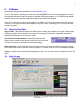
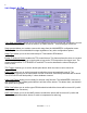
4 The main screen allows you to: - Configure the program preferences Configure the MAXIMIZER-II. Upload your saved configurations to the MAXIMIZER-II or download your configurations from the MAXIMIZER-II. Enter the monitor window for the MAXIMIZER-II. Log data to your PC 2.3 Program Set-up To open the program configuration menu, click on View and Options. 2.3.1 General Options Tab Serial Port allows you to select which COM port the software will use on your PC.
5 2.4 MAXIMIZER-II Configuration To start, click on File then New. 2.4.1 General Tab EGO Present allows you to select whether or not you have an O2 signal connected to the MAXIMIZER-II. A check mark in the box tells the MAXIMIZER-II that a signal is connected. Sensor Type allows you to set the type of sensor/controller being used. To set the type of sensor, click on the window to indicate “FJO Wideband” or “Narrow”. Note: For optimum performance and tuning capability, an FJO Racing Products (www.
6 b) Using a trigger signal from a coil - first determine how often it fires per revolution of the crankshaft. The correct setting would be: x1 for a waste-spark since it fires each revolution of the crankshaft x2 for a full-sequential since it fires every other revolution. MAP Present allows you to select whether or not you have the internal MAP sensor connected to the intake manifold of your engine. If connected, you can use the Map cutoff feature as well as log the MAP pressure.
7 AUTOMATIC PURGE – when the MAXIMIZER-II is armed, the output will automatically trigger your purge solenoid relay for the amount of time you set in the Purge Time setting. If you have the other GPO configured as BOTTLE OPENER, the AUTOMATIC PURGE will wait until the bottle open cycle is complete before doing a purge. If the bottle is already open (bottle heater enabled) it will purge immediately. Number of Gears allows you to set the number of gear profiles.
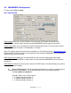
8 2.4.2 Stage 1 & 2 Tab Copy Data from Stage x allows you to copy all settings from the other stage and overwrite the current stage’s settings. Be careful as there is no UNDO function – current changes will be lost. Stage present allows you to add or remove this stage from the MAXIMIZER-II configuration menu. Removing the check mark disables this stage regardless of any other configuration options. Stage Type allows you to set the nitrous ramp to Time based or RPM based.
9 Trigger Switch #1 and Trigger Switch #2 can be configured to ENABLE, DISABLE or NOT CHANGE the arm status of a stage. (useful with a trans-brake, fuel pressure switch, or manual override) Choose Gear selects the gear that the current nitrous ramp profile is for. 2.4.2.1 Time Based Nitrous Configuration This mode uses the traditional Nitrous vs. time ramp. RPM Trigger allows you to set the minimum RPM required before the Nitrous can be triggered.
10 2.4.3 Saving and Uploading your Configuration It is recommended that you save your configuration and log files in the directory C:\Program Files\NX MAXIMIZER-II II To save your configuration on the PC, click on File then Save As… and enter a name for the configuration. It is possible to save multiple configurations on the PC, but only one config can be loaded into the MAXIMIZER-II. To upload a saved configuration to the MAXIMIZER-II, ensure the MAXIMIZER-II is turned on.
11 2.5.2 Data Logging To start logging click on the Logging button on the Main Screen or type L. You can data log with the Monitor screen open however it will reduce the number of data segments due to program overhead. For faster logging, close the monitor window. To turn off logging, toggle the logging button or type L. When logging is turned on, the automatically the PC creates a file using the following name format: “MAXIMIZER-II II 20050514-113305.
12 To begin, open the log file and then click the Analysis Plots button on the upper task bar. The X and Y-axis can be customized to display any combination of. This is done by selecting the items from the pull-down menus for each axis. For example, viewing EGO on the Y-axis and RPM on the X-axis will display your air-fuel ratio over your RPM range.
13 4. Disclaimer FJO Racing Products may not be held responsible for any damages, how so ever caused, to any persons or equipment during the installation or operation of its’ products. FJO’s products are meant for off-road use only, and make no claims as to the units' ability to meet local safety or emissions laws. 5. Warranty FJO Enterprises Inc. (FJO) warrants the material and workmanship of the equipment, components and parts manufactured by FJO against defects under normal use and service.
14 6.
15 6.2 Status LED 6.
16 6.4 Ignition Retard 6.
17 6.6 Automatic Purge 6.
18 6.8 WOT Switch Figure A illustrates how to connect a “HOT” wide-open-throttle switch. Set the WOT setting in the MAXIMIZER-II configuration to 4.5 volts, the TPS TRIGGER to 95%, and the IDLE to 0.5 volts. Figure B illustrates how to connect a “GROUND” wide-openthrottle switch. Set the WOT setting in the MAXIMIZER-II configuration to 0.5 volts, the TPS TRIGGER to 95%, and the IDLE to 4.5 volts. Note: The 1K ohm resistor is included in the kit. 6.