NX — rev A
i Table of Contents Page 1. Overview Overview................................................................ ................................................................... ................................................... 1 2. Software Installation ........................................................................... ................................................................... ................... 1 3. Software Software...............................................................
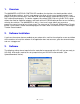
1 1. Overview The MAXIMIZER-3 NITROUS CONTROLLER combines the functions of a throttle position switch, two RPM window switches, and a 2 stage progressive driver all into a very compact module. It can progressively drive two channels, each with a 40 amp load capacity (continuous duty) or as 1 channel with a 80 amp load capacity .
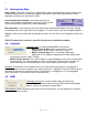
2 3 .1 Entering User Data Drag & Slide – data fields that have this feature have a down arrow button to the right. Clicking and holding the button causes a slider bar to appear. Moving the mouse left or right while the slider is displayed will decrease or increase the value. Increment/Decrement buttons - data fields that have this feature have up/down arrow buttons to the right. Click on either of these to increase or decrease the value accordingly.
3 a) Using a TACH signal - TACH signals will typically have 1 pulse per cylinder during 2 revolutions of the crankshaft (1 full cycle) and therefore the correct setting would be ÷(½ the number of cylinders) Example: When using a TACH signal 4 cylinder setting would be ÷2 6 cylinder setting would be ÷3 8 cylinder setting would be ÷4 Note: for LS1 tach signals set the multiplier to ÷2 b) Using a trigger signal from a coil - first determine how often it fires per revolution of the crankshaft.
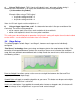
4 3.4.1 Time Based Curve Enable First-Gear Lockout disables the stage until the RPM has exceeded the RPM Cutoff at least once since it was powered on. T-Brake will determines what effect the transbrake will have on the applicable stage. Arm allows the stage to function normally while Disarm turns the stage off. If you are not using this input set it to Do NothingTo. RPM Cutoff allows you to set the upper RPM threshold above which the nitrous will be turned off.
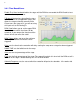
5 3.4.2 RPM Based Curve Enable First-Gear Lockout disables the stage until the RPM has exceeded the RPM Cutoff at least once since it was armed. T-Brake will determine what effect the transbrake will have on the applicable stage. Arm allows the stage to function normally while Disarm turns the stage off. If you are not using this input set it to Do NothingTo. RPM Cutoff allows you to set the upper RPM threshold above which the nitrous will be turned off.
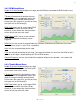
6 RPM Trigger allows you to set the minimum RPM required before the Nitrous can be triggered. Start sets the start percentage of the stage at 50% throttle. Final sets the final percentage of the stage at 100% throttle. Solenoid Frequency sets the rate at which the controller will pulse the solenoids. 14 hz works with most solenoids. 3 .5 Upload / Download Configuration DO NOT connect the controller to your PC until you have installed the software.
7 Blue Driver Wire (blue 12 awg) connects to the ground side of your stage 1 solenoids (fuel and nitrous) or the first 2 solenoids of a 4 solenoid single stage Red Driver Wire (red 12 awg) connects to the ground side of your stage 2 solenoids (fuel and nitrous) or the second 2 solenoids of a 4 solenoid single stage TACH Input (green) is designed to work with most Tachometer signals (down to 3 Volts), without the need for a separate adapter.
8 4.1.1 Wide-Open-Throttle Setup (Drive-by-wire) Note: It is recommended that you perform this on a test track or dynometer 1) Disconnect the solenoids from the relays to prevent them from firing. 2) Start the car and arm the MAXIMIZER-3. 3) With the engine idling, press and hold the TPS learn button until the RED, YELLOW and GREEN LEDs begin to flash. DO NOT change the throttle position until the GREEN LED stops flashing and goes out. If the GREEN LED begins to flash quickly, you have a bad TPS signal.
9 traction control module. For more details on this feature please refer to the Davis Technologies manual. 7. LED Indicators and Operation The LED’s, GREEN, YELLOW, RED are used to display the status of your MAXIMIZER-3 and are very useful in diagnosing problems. GREEN: FLASHING – indicates that the TPS WOT has not been programmed. In this case the unit will not fire any of the channels. Refer to the WOT set-up section for details on how to configure the box.
10 8. Software and Firmware Updates Free updates are available for the MAXIMIZER-3 and related software at www.nitrousexpress.com 9. Limited Warranty Nitrous Express (the warrantor) hereby warrants its product to the original purchaser thereof (the consumer) against any and all defects in workmanship and material under the following terms and conditions: The Limited Warranty is specifically limited to the original purchaser of the products and is enforceable only by such original purchaser.
Whi t e-