
Manual

N-TERCOOLER SYSTEM
INSTALLATION INSTRUCTIONS
The most important thing to do now is READ…
UNDERSTAND…AND …FOLLOW…these instruc-
tions. If there is something you don’t understand,
STOP! Call the factory tech department for help. 9:
00 AM to 4:00 PM CST 940-767-7694.
The installation procedures are divided into 5 sec-
tions. Please pay particular attention to each one:
1. Mounting the bottle
2. Routing the supply line.
3. Mounting the cooler ring
4. Wiring the system
5. Testing the system.
Before starting any installation steps:
1. Disconnect the negative battery terminal.
2. Never use Teon tape on any system ttings.
Tape debris will cause numerous problems rang-
ing from fouled solenoids to blocked jets. Use a
thread sealer such as Permatex 14AR or equiva-
lent Teon based sealant.
3. Have your bottle lled by a reliable source, being
sure it is lled to capacity with ltered “Nytrous
+” nitrous oxide or CO2. For lling station loca-
tions log on to: www.nitrousexpress.com.
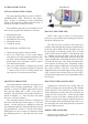
MOUNTING THE BOTTLE
The bottle should be mounted in the trunk area or
outside of the passenger compartment. If this is not
possible or practical a NHRA approved blow down
tube and vent tting (PN’s 11708, 11709) must be
installed. The positioning of the bottle should be as
shown in diagram “A”. This will allow the siphon
tube to be covered at all times.
The mounting brackets should be assembled on
the bottle with the short bracket approx. 2” from the
bottom.. Use this mock up as a template to locate the
four mounting bolt holes. The bottle should be secured
by a minimum of 4 “Grade 5” 5/16 bolts. Note: Before
drilling holes be sure to check for clearance beneath
the mounting surface i.e.: fuel tank, fuel lines, brake
lines.
DIAGRAM A
ROUTING THE FEED LINE
NOTE: Place a piece of tape over both ends of
the hose to prevent debris from entering the feed line
during the routing process.
The feed line may be routed to the engine com-
partment either through the passenger compartment or
under the vehicle. Route the line carefully to prevent
the possibility of restricting nitrous ow. If routed
under vehicle, locate and drill a inch diameter hole
in a suitable area near the bottle valve for the main
line. Starting at the bottle nipple route the line to the
engine compartment. Following the factory fuel lines
is usually the best path. Note: Keep maximum clear-
ance between all moving parts, suspension compo-
nents and hot engine components, securing the supply
line where possible (“Zip-Ties” work best here).
Tighten the line to the bottle nipple securely. Be espe-
cially careful of the feed line being near any “HOT”
electrical leads a spark will cause a permanent leak in
the feed line.
MOUNTING THE COOLING RING
Assemble the solenoid to the cooling ring, the
1/8 NPT discharge port on the bottom of the solenoid
mounts directly to the cooling ring. Thread the xD-
4 lter tting into the inlet port of the solenoid, the
supply line will connect here. Teon based sealant
should be used to avoid leaks. Mount the NX cooler
ring on your intercooler using the supplied zip ties, do
not over tighten, intercooler damage may result. Con-
nect the supply line to the inlet port on the solenoid at
this time, tighten securely.
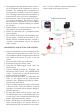
WIRING THE SOLENOIDS
1. Mount the red arming switch within easy reach,
and plain sight of the driver.