
User's Manual


ILD-IN’O User Guide
All Rights Reserved – nke Watteco® ILD-IN’O User Guide
Page 7 of 9
4 HUMAN MACHINE INTERFACE
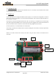
There is three leds on the ILD and IN’O devices:
ASS: blinking until the association to a network is done.
FNC: blinking each minute while an input is activated.
CNF: blinking in the configuration mode.
A button user is available to enter in configuration mode.
5 APPLICATIVE LAYER
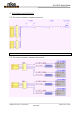
The ILD and IN’O device is a sleepy device. It implements “ON/OFF” and “Binary Input” clusters, associated to
their Outputs and Inputs. The corresponding between the connectors and the EndPoint is done below:
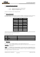
Connector
End Point
Cluster
Output 1+/1-
0
ON/OFF
Output 2+/2-
1
ON/OFF
Output 3+/3-
2
ON/OFF
Output 4+/4-
3
ON/OFF
Input 1+/1-
0
Binary Input
Input 2+/2-
1
Binary Input
Input 3+/3-
2
Binary Input
Input 4+/4-
3
Binary Input
Input 5+/5-
4
Binary Input
Input 6+/6-
5
Binary Input
Input 7+/7-
6
Binary Input
Input 8+/8-
7
Binary Input
Input 9+/9-
8
Binary Input
Input 10+/10-
9
Binary Input
All the End Points are avalaible by software on ILD or IN’O, only the hardware is different between the two kinds
of sensor. Grey field are not available on the ILD sensor.
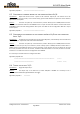
ILD and IN’O integrate clusters:
Cluster
Cluster name
Managed attributes
0x0000
Basic
All
0x0050
Configuration
All
0x0006
ON/OFF
All
0x000F
Binary Input
All
6 EXAMPLES
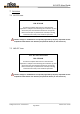
6.1 CONFIGURE A STANDARD REPORT ON THE CONNECTOR INPUT 1+/1-
Specification: Report immediately the counter all the 5 pulses on the connector Input 1+/1-. The counter has
to be reported at least each hour.
Solution: A counter on Input 1+/1 is the End Point 0, Cluster “Binary Input” is 0x000F, Attribut “Count”
is 0x0402. The maximum field has to be 0x0e10 to have a report all one hour and the minimum field has to be
0x0000 to have a report immediately after the right incrementation. The right incrementation, so the delta has
to be configured to 0x05 for a report all the 5 pulses.