
Datasheet

J
Series JB
Low Profile Process Sealed Tactiles
www.nkk.com
J21
Indicators
AccessoriesSupplement Tactiles KeylocksRotaries PushbuttonsIlluminated PBSlides Programmable Rockers
Touch
Tilt
Toggles
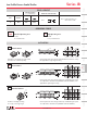
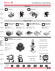
Special bracket for right angle mounting provides added design
variations.
Higher operating force type provides more pronounced
operating feel.
Rubber seal construction prevents contact contamination
and allows automated soldering and cleaning.
Choice of dimensions from PCB to top of cap allows
design flexibility.
Dome contact gives crisp tactile feedback to positively indicate
circuit transfer and assures high reliability and long life of up
to 5,000,000 operations.
Slanted terminals provide a spring type action which ensures secure
mounting and prevents dislodging during wave soldering.
Molded-in terminals are part of the sealed construction which allows
automated soldering and washing.
Terminal spacing conforms to standard .100” (2.54mm) PCB grid.
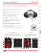
Actual Size
Distinctive Characteristics
1
2
3
65
4
7
8
9
B
0
A
9
13
10
6
11
8
12
72
1
3
4
5
1
2
3
4
5
6
7
8
9
0
A
B
1234 56789101112
13
= ON
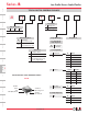
Keys (Switches)
PC Terminations
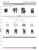
1
2
3
65
4
7
8
9
B
0
A
1
2
6
7
34
5
1
2
3
4
5
6
7
8
9
0
A
B
1234 567
= ON
Keys (Switches)
PC Terminations
Common Bus Matrix
These single pole, single throw switches can be used in a key-
board matrix and, using strapped terminals, achieve a com-
mon bus electrical configuration on a single-sided PC board.
X-Y Matrix
These single pole, single throw switches can be
arranged on a single-sided PC board matrix
with strapped terminals to achieve an X-Y type
electrical interconnection.
Red = PCB Trace Black = Switch Circuit