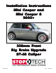
Installation Instr uctions Mini Cooper and Mini Cooper S 2002+ 328mm Front Big Brake Upgrade ST-40 Caliper 98-138-1430 Rev.
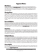
COMPONENT IDENTIFICA TION IDENTIFICATION AeroRotor and Hat Assemblies High-Performance Street Pads Caliper Brackets Calipers Stainless Steel Braided Lines and Hardware Front B ig B rake K it for the Big Brake Kit Mini Cooper and Mini Cooper S (This is a representative photograph. The actual components in your kit may appear slightly different.) 3541 Unit A, Lomita Boulevard, Torrance, CA 90505 (310) 325-4799 www.stoptech.
APPLICA TION DISCL AIMER APPLICATION DISCLAIMER Caliper Clearance Most 17” wheels will clear the outer diameter of the caliper for a 328mm or 332mm rotor kit. For a 355mm kit, a minimum 18” wheel is typically required, and for a 380mm rotor kit, a minimum 19” wheel is needed. The more critical clearance, however, is the gap between the spokes of the wheel and the face of the caliper. Do not assume that a larger-diameter wheel will automatically clear the face of the caliper.
APPLICA TION DISCL AIMER (Cont APPLICATION DISCLAIMER (Cont’’d.) Per manent R emo ust SShield hield ermanent Remo emovval of D Dust The dust shield must be permanently removed from both front wheels of the vehicle, to accommodate the AeroRotors. Brake N oise Noise Certain brake pad compounds make more noise than others. Proper anti-squeal shim plates between the caliper pistons and backing plate of the pad help to reduce the problem. Anti-squeal lubricants are also available, to reduce some of the noise.
Impor tant N otices mportant Notices Wheel F itment Fitment Do not assume that your wheels will fit. An outline drawing of your StopTech Big Brake kit is .stoptech.com available on our website at www www.stoptech.com .stoptech.com. Measure the distance from the outer face of your stock caliper to the inner face of your wheel spokes, or make a template according to the instructions on the website, to determine if a wheel spacer is necessary.
Front Axle K it for the Kit Mini Cooper and Mini Cooper S Note: IItt is impor tant to rread ead and understand this ENTIRE installation manual, including the important bed-in procedure, before starting the installation.
Front Axle K it for the Kit Mini Cooper and M ini Cooper S (Cont Mini (Cont’’d.) Tools and E quipment R equir ed Equipment Requir equired Different models and years of vehicle use different-sized fasteners, and every effort has been taken to correctly identify the proper sized tool for each step of the installation. Occasionally, however, manufacturers may use an alternate fastener, so it’s advisable to check that each tool correctly fits the fastener before loosening or tightening it.
Step 1 R aise Vehicle, and R emo Remo emovve Wheels Note: All photographs show a right-hand side installation, unless otherwise noted. Some of the images in this manual may not be of the vehicle noted, but tion of the corr ect installation. S topT ech rrecommends ecommends wor king correct StopT topTech working time, so that reference can be made to the other side, if any installation.
Step 2 Disconnect SStock tock B rake Line Brake War ning: S pilled br ake fluid will damage most painted sur faces, and should be cleaned off arning: Spilled brake surfaces, immediately ake car ely installed on the master cylinder immediately.. T Take caree to ensur ensuree that the cap is secur securely cylinder.. If it is loose or removed, it is likely that more fluid will drip during brake installation. Place a drip tray or several rags directly below the inboard brake line connection.
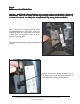
Step 3 Remo tock C aliper & R otor emovve SStock Caliper Rotor Remove the two stock caliper bolts, using a 16mm wrench or socket. Note: F actor y-installed caliper bolts may be Factor actory-installed very tight. Ensure that you have a good purchase on the bolt head, and that you are in a good position to turn the wrench or socket. Remove the caliper with the stock brake line attached.
Step 4 Remo ust SShield, hield, and IInstall nstall C aliper B racket emovve D Dust Caliper Bracket The dust shield must be permanently removed from each front wheel, to accommodate the AeroRotors. Remove the dust shield retaining screws, using a T-25 Torx wrench, then slide the dust shield off of the hub. Note: Due to their close proximity to the hub, an L-shaped wrench may be required to remove the dust shield retaining screws.
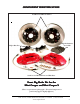
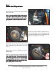
Step 5 Install AeroRotor Assembly AeroRotors MUST be cleaned with soap and water prior to installation. Not doing so will damage the rotors and pads, and will prevent the brakes from performing properly. Even though the rotors may look clean, the rust inhibitor is in place, and it must be removed. Not cleaning the rotors will severely impact the performance of your new brake system.
Left-Side Rotor Outboard Side Driv er river er’’s Left Right-Side Rotor Outboard Side Driv er river er’’s Right 3541 Unit A, Lomita Boulevard, Torrance, CA 90505 (310) 325-4799 www.stoptech.
3541 Unit A, Lomita Boulevard, Torrance, CA 90505 (310) 325-4799 www.stoptech.
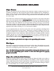
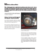
Caliper Component IIdentification dentification Bolt-in Bridge Pad Retaining Clip Cross Over Tube Bridge Bolts Bleed Screw Use a light film of anti-seize on the bridge bolt shafts and threads The ST-40 original equipment caliper uses a common Porsche-style pad. The Friction Materials Standards Institute (FMSI) number for the pad backing plate is D372. For further pad interchange information, please see the FAQ section of the StopTech website at: www.stoptech.
Step 6 Install C aliper and P ads Caliper Pads Note: The images in this section may not be of the vehicle noted, but they give a proper representation of the correct installation. Determine the left- and right-hand side calipers. They are clearly marked on the box, but as a check, the bleed screws are always positioned at the top of the caliper. If installing a four-wheel kit, with ST40 calipers on the front and rear of the vehicle, be sure that the correct caliper is on each corner.
Step 6 (Cont (Cont’’d.) Install C aliper and P ads Caliper Pads Install the caliper onto the adapter bracket, orienting it so that the bleed screws are positioned on the top side of the caliper. Take care to ensure that the caliper is square and evenly started on both studs. It may be necessary to use a mallet to gently tap the caliper into position. Install the Jet nuts onto each stud, with one 12mm washer under each nut. Tighten the Jet nuts to 40 lb-ft of torque, using a 1/2” socket.
Step 6 (Cont (Cont’’d.) Install C aliper and P ads Caliper Pads Apply a light film of anti-seize compound onto the bridge bolt shafts and threads. Install the bridge by sliding it into position, and rocking it until one of the bolt holes lines up. Take care to ensure that the bridge is slid straight and parallel into the caliper body opening. Note: The bridge is directional, and should be positioned so that the air-scoop opening is located in the top half of the bridge.
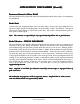
Step 7 Attach SStainless tainless SSteel teel B rake Line Brake Install the caliper end of the stainless steel brake line by first placing a copper crush washer on either side of the banjo fitting, then inserting the banjo bolt into the caliper. Copper crush washers Banjo bolt oximately 14 lbTorque the banjo bolt to appr appro ft ft, using a 14mm wrench or socket. Do not use a torque wrench, as overtightening the bolt can strip the aluminum threads, causing irreparable damage to the caliper.
Step 7 (Cont (Cont’’d.) Attach SStainless tainless SSteel teel B rake Line Brake Install the inboard end of the brake line by first placing a stainless steel washer over the end fitting. Remove the rubber cap from the chassis hard line. Then insert the stainless steel brake line fitting through the chassis bracket, and screw it onto the hard line fitting by hand for a few turns, to ensure that it is properly engaged.
Step 8 Bleed Brakes Complete the installation on both sides of the vehicle before bleeding the system. War ning: D ouble-check that the stainless steel br ake lines yyou ou arning: Double-check brake ou’’ve just installed ar aree not binding in any way, nor interfering with any suspension component, including the CV boot and the axle/ driv ealigning the br ake drivee shaft.
Step 9 Reinstall Wheels It is very important to check the wheel-to-caliper clearance before installing wheels! Note: S ome wheels ar e-backed lead w Some aree balanced on the inside, with adhesiv adhesive-backed weights. eights. If the fer weight is on the outboar d edge, behind the spokes, it may inter outboard interfer feree with the caliper caliper..
AeroRotor Installation & Bed-in Procedure READ THIS NOW FAIL URE TO READ, UNDERST AND AND FOLL OW THESE PR OCEDURES AILURE UNDERSTAND FOLLO PROCEDURES WILL CA USE P ERMANENT DAMA GE TO YOUR BRAKE R OTORS, AND WILL CAUSE PERMANENT DAMAGE RO KEEP THE SYSTEM FR OM WORKING A T IT S FULL CAP ACIT Y. FROM AT ITS CAPA CITY The majority of brake system problems are due to improper installation and/or bed-in of the rotors and pads.
Rotor and P ad Bed-in (Cont Pad (Cont’’d.) Note: B edding-in of pads should not be done in poor w eather conditions, nor on w et rroads. oads. Bedding-in weather wet After completing the installation, make a series of 10 stops from 60 to 5-10 MPH. At the end of each stop, immediately accelerate to 60 again for the next stop. Run all stops in one cycle. During the 60 to 5-10 MPH cycle of stops, the exact speed is not critical. Accelerate to approximately 60, then begin braking.
Thank yyou ou for selecting SStopT topT ech. topTech. We realize that you had a choice when selecting a big brake upgrade for your vehicle, and we know that you’ll be happy with our system. We proudly support our fine products. For any assistance or questions, please contact our Customer Service Department at (310) 325-4799 - extension 105 or e-mail us at support@stoptech.