
User manual


Installation
Electrical connection for UK only
Safety warnings for the electrician
Connect the hood to the mains supply via a double
pole switch which has 3 mm minimum separation
between the contacts.
The switch must be accessible at all times.
The following is valid in the United Kingdom
only:
- the wire which is coloured green and yellow
must be connected to the terminal which is
marked with the letter E or by the earth symbol
( ), or coloured green or green and yellow;
- the wire which is coloured blue must be
connected to the terminal which is marked with
the letter N or coloured black, -
- the wire which is coloured brown must be
connected to the terminal which is marked with
the letter L or coloured red.
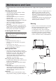
Installing the hood in a cabinet
The locking screws must be in place (x
2). If this is not the case, the hood could
drop.
1. Trace a line using the installation template to
guide you (Fig. 8). Saw along this line and cut a
groove at the base of the top part of the cabinet.
2. Measure the thickness of the cabinet walls
(Fig. 9). The most common wall thicknesses are
16 and 19 mm. If the thickness is any different,
choose the closest thickness.
3. Install the suspension bars (Fig. 9) on the
installation template. The drawings illustrate
the left-hand side of the cabinet. Fig. A for 16
mm cabinets and fig. B for 19 mm cabinets.
4. Push the installation template against the side
of the cabinet and secure the fastening bars with
screws (Fig. 10).
5. Turn the suspension bar by half a turn when it
is installed on the right-hand side of the cabinet.
6. Raise the hood and insert the hooks in the
special slots.
7. Push the hood against the wall. Check that all
the hooks are correctly inserted in the slots.
8. Install the locking screw (Fig. 11).
80 mm
A
B
1.
2.
3.
4.
~16
~19
3
2
1
Fig. 8
Fig. 9
Fig. 10
Fig. 11