
User manual

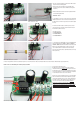


Now the first test of the building lighting is performed.
Make absolutely sure that the LEDs are not touching each other and that the traction power does not come in contact with the lead wires of the LEDs.
Connect the power supply of our switch (black and red cable of the connections BLACK / RED) to the continuous current output of the transformer (16 volts alternating current AC).
No matter which pole will be connected to which contact.
Immediately after switching on, the LED being connected to the resistance and to the contact R+ starts to light.
How does the programme of the microprocessor work exactly?
In the microprocessor a program is stored. This program turns the connected LEDs on or off in certain time series.
Transformed into the daily life, the program does the following:
In the kitchen the light is on (R+ at ON). After 5 seconds the light in the living-room will be turned on and the light in the kitchen will be turned off (L1 at ON and R+ at OFF). 8 seconds
elapse and the light in the bathroom will be turned on (L2 at ON). After further 10 seconds the light in the living room will be turned off and in the kitchen the light will go on (L1 at OFF
and R+ at ON). It takes 15 seconds, after this the light in the bathroom turns off. Now, after 10 seconds, finally: The TV will be turned on. During the TV is on, the light in the bathroom
will go on and right away off. After this, the lights in the living room and in the kitchen will be turned on again….
How the LEDs are installed into the light cases?
• Assemble the light cases.
• Open the holes for the LED.
• Glue them in front of the windows from inside.
• Install one or more LEDs and fix with glue.
FINISHED!!!
Is a life without TV possible?
Yes, it is: In the microprocessor two programs are stored. There is a programme “with TV” and one “without TV”.
How can I start the second programme?
First always switch off the power. Now, the jumper that leads from contact SW to -M- will be soldered in another way. As presented in the following (picture 20), now, the jumper leads
from SW to +.
At the beginning of the program the microprocessor tests the entry. Either the cable is located at -M- (minus) or like now at +. Thus the microprocessor knows that the second program
(without TV) shall be performed.
During this program the outlets will be turned on and off in certain time intervals. Only the lighting of the TV is missing now. Now, it’s better to install a white or even a yellow LED
instead of the blue one at the outlet.
I want to have a TV again!
First make sure that the power is turned off. Then connect the connection SW with the contact -M- again. Now the first program is used and the TV is lighting again.
We absolutely want to have a fireplace!
If you use a red LED instead of the blue LED, the flutter of the red LED can simulate a fireplace.
In the living room there shall be a yellow warning light.
For this two yellow LEDs will be interconnected parallel. Thus two long legs to the red cable and two short legs of the both LEDs to the black cable. Means, that the two minus poles
(cathodes) and the two plus poles (anodes) will be interconnected, a so-called parallel-connection.
The light in the living room shall be brighter now.
Now, the second resistor is used.
The second resistor will be connected parallel to the first. That means that the two connections will be interconnected. By using the resistors you can ignore the polarity in contrast to
the using of the LEDs. The effect results, that the value of the resistance will be cut in half. 330 Ohm divided by 2 = 165 Ohm. The connected yellow LEDs are brighter now.
We want to have an exterior lamp!
This exterior lamp shall light permanently. Therefore we need the resistor, which is connected parallel. So, desolder this resistance. Now, the contacts of the plug connector will be
formed for an easier soldering. The upper contact will be formed upwards and the middle contact a little bit to the right (picture 23).
The resistance to the middle contact and the resistance to the red cable on a LED. Solder the black cable on the upper contact of the plug connector.
We want to have homely warm white light.
It’s very easy with nail polish. Therefore, the LED will be colored. Here, light brown nail polish is used. You can remove it with a nail polish remover. Well suited is one “without acetone”.
How to interconnect LEDs?
As shown above, the LEDs can be connected parallel. You can connect two or three or more LEDs parallel.
You can also connect components parallel, which means the components will be connected in series (series connection). Important: Pay attention to the polarity of the LEDs. Solder the
short wire of the red LED on the long wire of the white LED. Then the red cable on the long wire of the red LED and the black cable on the short wire of the white LED.
Please work closely and carefully!!!
It works only in this way!
A parallel connection and a series connection look like this.
• A blue LED as “TV”.
• Three with nail polish colored LEDs connected parallel for the living room.
• Two yellow LEDs also connected parallel for the bathroom.
• A red and a white LED in series connection for the kitchen.
There are many possibilities to interconnect LEDs.
In general the white LEDs can be interconnected. Here you can connect up to four white LEDs parallel at an outlet.
IMPORTANT: Don’t connect more than 4 LEDs per outlet!