
Installation Guide

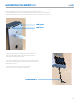

WIRING THE NOKĒ PAD
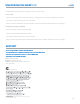
SETTING UP THE NOKĒ PAD
04
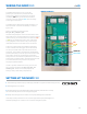
RELAY OUTPUTS
NC
COM
NO
+24V DC
GROUND
The Nokē Pad requires a 12V or 24V DC
power input. Connect the positive terminal
of the power supply to the push pin connector
marked by 24V. The ground terminal needs to
connect to the port marked GND. See the image
to the right for reference.
The Nokē Pad is designed to trigger the Relay 1 on
the board when a correct number key is entered
by the user.
Relay 1’s outputs are mentioned as:
RL1_NC, RL1_COM, RL1_NO.
Use this Relay output to connect to the electric lock
that needs to be controlled. Based on how the electric
lock functions, you would need to use either the NC
or NO port to operate the electric lock. Check the
wiring diagram of the electric lock you’re using to
understand how the lock needs to be connected.
There are 3 other Relays on board the Nokē Pad.
These could be used to trigger other locks based
on how you would want to provide access to the
end users. In the future, the Nokē Pro App/Desktop
portal would allow you to set up access control rules
such that a certain pin would trigger a particular
Relay, which is connected to a particular lock. These
extra Relays could be used to provide/restrict access
to certain doors/access points to only certain
employees/administrators.
If such a system needs to be set up, you can use
the connector ports that say RL2_xxx, RL3_xxx
and RL4_xxx. These are the relay outputs of
Relay 2, Relay 3 and Relay 4 respectively.
1. Install Storage Smart Entry by Nokē app (available in Apple and Android app stores).
2. Add keypad as new device.
3. SecurGuard powered by Nokē Mesh Hub (required, available from Janus)
will automatically discover and configure keypad.
4. Setup and manage access codes via Property Management Software.
Visit https://www.janusintl.com for a list of approved Property Management
Software packages or contact us for a custom integration quote.