
User Manual

6-58 Configuring, Installing, and Using Carrier Infrastructure
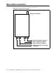
Ethernet/power connecting cable
Depending on your needs, you can order any of the following cables to connect the base
station to the TVS module.
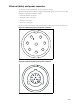
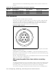
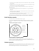
Table 6.2 describes the pins of the Ethernet/power cable that connects the base station to the
TVS device.
Table 6.3 describes the color and function of the wires in cable 597-6027-0xxx.
Table 6.1 Ethernet/power base station cable choices
Cable part number Length (feet)
597-6027-0002 2
597-6027-0004 4
597-6027-0006 6
597-6027-0010 10
597-6027-0025 25
597-6027-0050 50
597-6027-0100 100
597-6027-0200 200
597-6027-0300 300
Table 6.2 Ethernet/power cable pins
Pin TVS connection Base connection
1 Tx+ -48 VDC
2 Tx- -48 VDC
3 Rx+ +48 VDC
4 Rx- +48 VDC
5+48 VDC Rx-
6+48 VDC Rx+
7 -48 VDC not used
8 -48 VDC not used
9Tx-
10 Tx+
11 not used
12 not used
13 not used
Table 6.3 Function of wires in cable 597-6027-0xxx
Wire color Wire function
White/orange Tx+ Ethernet
Orange Tx- Ethernet
White/green Rx+ Ethernet
Green Rx- Ethernet
Red +48 VDC
Red/white +48 VDC
Black -48 VDC
Black/white -48 VDC