
User Manual

7-78 Configuring, Installing, and Using Carrier Infrastructure
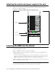
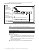
Base station connectors
This section describes the GPS connectors and the serial cable connectors. The serial cable is
used to configure the base station with information that is unique to the carrier.
GPS connectors
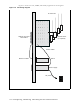
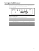
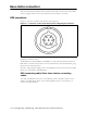
Figure 7.7 shows the connectors that the base station supports.
An RS-422 line feeds 1PPS+ and 1PPS- with the time synchronization pulse from the GPS
equipment to the base station.
An RS-422 line also feeds 422Data+ and 422Data-, to allow data communication from the
GPS device to the base station. This is one-way communication, with the GPS device giving
the base station time information.
The 18V+ and ground pin supply power to the GPS device from the base station. The GPS
device uses 18 volts DC at 150 milliamperes.
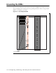
GPS connecting cable/Inter-base station connecting
cables
You need one GPS device per cell. You then directly connect one GPS connector on the
cabinet to the GPS device. Then, on the remaining GPS connector on the cabinet, you
connect the load termination.
Figure 7.7 Connector on the serial cable used in configuring base stations