
User Manual
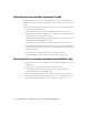
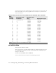
Table Of Contents
- Preface Overview
- About this guide
- Additional documentation
- Typographical conventions this guide uses
- Where to go for more help
- Chapter overview
- System overview
- Installation overview
- Planning the installation
- Chapter overview
- Before you begin
- Using Terminal Emulation or Telnet to help configure base stations
- Setting base station configuration parameters
- Chapter overview
- Before you begin
- Cell wiring
- Base station connectors
- Mounting the base station
- Connecting the antenna to the base station
- Connecting the GPS equipment to a base station
- Connecting to the backbone network
- Powering base stations
- Verifying system operation
- Appendix overview
- Appendix overview

2-9
Connecting through terminal emulation
The terminal emulation connection is a physical RS-232 cable connection, between
the base station and a PC. Once the connection is made, you can use a program
such as Hyperterminal under the Windows operating system to configure and
communicate with the station.
Before installing a base station, it is recommended that you assign the base station
a name, using terminal emulation and the “set name” and “set location”
commands in NNOS. Assigning a name makes it easier for you to identify the
device in the network. Also, depending on IP lease time, an IP address can change
each time you power on the base station or reset it.
Terminal emulation connection settings
To set up a terminal emulation connection, use these settings:
• 19.2 baud
•8 data bits
• No parity
• 1 stop bit
• no flow control
Setting base station configuration parameters
This section describes configuration parameters you must set for proper base
station functioning.
You can use Telnet, terminal emulation, the NNOS web interface, or an SNMP
session to configure the parameters on the base station.
When setting up the base station, you must:
1 Set the following parameters, in the order that follows:
• set airlink channel number
• set airlink downlink power
• set airlink downlink bias
• set airlink state
2 After setting the parameters, use the write command to write the settings into
the flash, non-volatile memory.