
User Manual
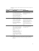
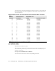
Table Of Contents
- Preface Overview
- About this guide
- Additional documentation
- Typographical conventions this guide uses
- Where to go for more help
- Chapter overview
- System overview
- Installation overview
- Planning the installation
- Chapter overview
- Before you begin
- Using Terminal Emulation or Telnet to help configure base stations
- Setting base station configuration parameters
- Chapter overview
- Before you begin
- Cell wiring
- Base station connectors
- Mounting the base station
- Connecting the antenna to the base station
- Connecting the GPS equipment to a base station
- Connecting to the backbone network
- Powering base stations
- Verifying system operation
- Appendix overview
- Appendix overview

2-11
set airlink downlink power
This parameter specifies the base station’s transmit power level. Specify a power
value from 0 to 31.
The maximum system power level is 10, which specifies +33 dB at 2 watts. The
other power levels are measured in 1 dB steps from the maximum.
Example:
set airlink downlink power 10
set downlink bias
This parameter specifies the portion of airtime (slots) available for use on the
downlink relative to the airtime for the uplink. There are always 6 slots available for
the uplink.
The higher the bias, the more bandwidth is available for the downlink, due to more
time allocated to the downlink.
Example:
set airlink downlink bias 9
Table 2.1
Base station transmit power level
Power value Power level
10 +33 dBm or 2.0 watts
.
.
13 +30 dBm 1.0 watt
.
.
16 +27 dBm 500 milliwatts
.
.
23 +20 dBm 100 milliwatts
.
.
31 +12 dBm 15.8 milliwatts