
User Manual
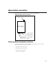
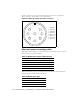
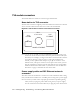
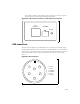
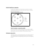
Table Of Contents
- Preface Overview
- About this guide
- Additional documentation
- Typographical conventions this guide uses
- Where to go for more help
- Chapter overview
- System overview
- Installation overview
- Planning the installation
- Chapter overview
- Before you begin
- Using Terminal Emulation or Telnet to help configure base stations
- Setting base station configuration parameters
- Chapter overview
- Before you begin
- Cell wiring
- Base station connectors
- Mounting the base station
- Connecting the antenna to the base station
- Connecting the GPS equipment to a base station
- Connecting to the backbone network
- Powering base stations
- Verifying system operation
- Appendix overview
- Appendix overview

3-15
Base station connectors
Figure 3.2 shows the connectors that the base station supports.
Ethernet (data) and power connector
The Ethernet and power connector supplies data and DC power to the base
station. The circular connector has 8 pins:
• Ethernet transmit uses 2 pins.
• Ethernet receive uses 2 pins.
• Power ground uses 2 pins
• Power V+ uses 2 pins.
Figure 3.2
Base station connectors
Base Station
Antenna Connector
J4 - Serial Connector
J3 - GPS Connector
J2 - GPS Connector
J1 - Ethernet/Power
Connector