
User Manual
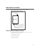
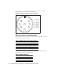
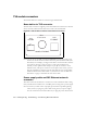
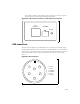
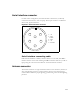
Table Of Contents
- Preface Overview
- About this guide
- Additional documentation
- Typographical conventions this guide uses
- Where to go for more help
- Chapter overview
- System overview
- Installation overview
- Planning the installation
- Chapter overview
- Before you begin
- Using Terminal Emulation or Telnet to help configure base stations
- Setting base station configuration parameters
- Chapter overview
- Before you begin
- Cell wiring
- Base station connectors
- Mounting the base station
- Connecting the antenna to the base station
- Connecting the GPS equipment to a base station
- Connecting to the backbone network
- Powering base stations
- Verifying system operation
- Appendix overview
- Appendix overview

3-16 Configuring, Installing, and Using Base Stations
Figure 3.3 shows the pins of the Ethernet and power connector on the base
station, looking at the connector on the base station.
Ethernet/power connecting cable
Depending on your needs, you can order any of the following cables to connect
the base station to the TVS module.
Table 3.2 describes the pins of the RJ-45 cable (the Ethernet/power cable) that
connects the base station to the TVS device.
Figure 3.3
Ethernet (data) and power connector
Table 3.1
RJ-45 base station cable choices
Cable part number Length (feet)
597-6013-0010 10
597-6013-0025 25
597-6013-0050 50
597-6013-0100 100
597-6013-0200 200
Table 3.2
RJ-45 cable pins
Pin Connection
1Tx+
2Tx-
3Rx+
28
1
6
7
4
5 3
1 - EN TD+
2 - EN TD-
3 - EN RD+
4 - EN RD-
5 - Power V+
6 - Power V+
7 - Power V-
8 - Power V-