
User Manual
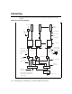
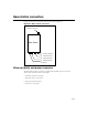
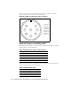
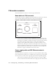
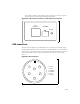
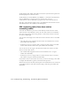
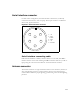
Table Of Contents
- Preface Overview
- About this guide
- Additional documentation
- Typographical conventions this guide uses
- Where to go for more help
- Chapter overview
- System overview
- Installation overview
- Planning the installation
- Chapter overview
- Before you begin
- Using Terminal Emulation or Telnet to help configure base stations
- Setting base station configuration parameters
- Chapter overview
- Before you begin
- Cell wiring
- Base station connectors
- Mounting the base station
- Connecting the antenna to the base station
- Connecting the GPS equipment to a base station
- Connecting to the backbone network
- Powering base stations
- Verifying system operation
- Appendix overview
- Appendix overview
3-20 Configuring, Installing, and Using Base Stations
An RS-422 line feeds 1PPS+ and 1PPS- with the time synchronization pulse from
the GPS equipment to the base station.
An RS-422 line also feeds 422Data+ and 422Data-, to allow data communication
from the GPS device to the base station. Currently, this is one-way
communication, with the GPS device giving the base station time information.
The 18V+ and ground pin supply power to the GPS device from the base station.
The GPS device uses 18 volts DC at 150 milliamperes.
GPS connecting cable/Inter-base station
connecting cables
You need one GPS device per cell. You then directly connect one base station
within that cell to the GPS device. Next, the other base stations are connected to
each other, using a daisy chain wiring scheme, so that all base stations in the cell
can receive a GPS signal.
You can choose the length of the cable that connects the base station to the GPS
receiver.
• The cable that comes standard in the base station site installation kit is 100 ft
(part number 597-6011-0100).
• If desired, you can use a shorter cable to connect the base station to the GPS
receiver. This alternate cable is 25 ft (part number 597-6011-0025).
You can also choose the length of the daisy-chain cable that connects one base
station to another base station.
• The standard cable shipped in the base station installation kit is 3 ft (part
number 597-6012-0003).
• If desired, you can use a longer cable to connect one base station to another.
This cable is 10 ft (part number 597-6012-0010)
If you need to remove a base station for service, you can use the longer, 10 ft. cable
to jumper the GPS cables together, and continue cell operation.
The last base station in the daisy chain requires a load termination to be connected
to the GPS connection. This base terminator plug is 100 ohm (part number 515-
6005-0001).