
User Manual
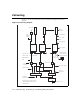
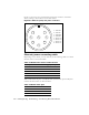
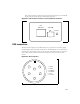

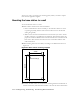
Table Of Contents
- Preface Overview
- About this guide
- Additional documentation
- Typographical conventions this guide uses
- Where to go for more help
- Chapter overview
- System overview
- Installation overview
- Planning the installation
- Chapter overview
- Before you begin
- Using Term or Telnet to help configure base stations
- Setting base station configuration parameters
- Chapter overview
- Before you begin
- Cell wiring
- Base station connectors
- Mounting the base station
- Connecting the antenna to the base station
- Connecting the GPS equipment to a base station
- Connecting to the backbone network
- Powering base stations
- Verifying system operation
- Appendix overview
- Appendix overview

3-19
base station connector side, the base station will power up, but you will NOT
be properly protected against possible lightning strikes.
GPS connectors
The base station supports two GPS connectors: one connector is used to supply
the GPS signal, either by a direct connection to the GPS device, or by a daisy chain
connection to another base station in the cell. The other GPS connector is used to
make a daisy-chain connection from the current base station to the next base
station.
Figure 3.5
TVS module connector: Power/Ethernet connector
ISP
Ethernet +48 VDC
Power
+ -
Figure 3.6
GPS connector
51
3
2 4
1 - 1PPS+
2 - 1PPS-
3 - 422Data+
4 - 422Data-
5 - 18V+
6 - Ground
6